Table of Contents
Advertisement
Advertisement
Table of Contents

Related Manuals for Veolia HYDROTECH 12 Series


Summary of Contents for Veolia HYDROTECH 12 Series
- Page 1 Drumfilter HDF - 12/16/20/24 -series Operation and maintenance manual...
-
Page 2: Table Of Contents
LIST OF CONTENTS 1. INTRODUCTION 2. SAFETY INSTRUCTIONS 2.1 Warning symbols 2.2 CE marking 2.3 Conversion 2.4 Personnel requirements 2.5 Emergency stop 2.6 Electrical safety 2.7 Safety instructions 3.1 Overview 3.2 Identifying the filter 4. RECEPTION AND HANDLING 4.1 Reception 4.2 Storage 4.3 Lifting the equipment 5. - Page 3 5.6 Pipe connections 5.7 Backwash system 5.8 Filter placement 6. START-UP AND OPERATION 6.1 Check procedures during start-up 6.2 Automatic settings 6.2.1 Level differences 6.2.2 Operating mode HAND – continuous rotation/washing 6.2.3 Operating mode AUTO – automatic level control 6.2.4 Adjusting the level sensor 6.2.5 Adjusting delay time 6.2.6 Setting the level relay 6.3 Backwash system...
- Page 4 8.3.2 Checking centre bearings for wear 8.4 Filter element 8.4.1 High pressure cleaning 8.4.2 Chemical cleaning of filter elements 8.4.3 Replacing filter elements 8.5 Drive chains, drives with roller chains 8.5.1 Checking the drive chain for wear 8.5.2 Checking drive chain tension 8.5.3 Adjusting drive chain tension 8.5.4 Replacing the drive chain 8.6 Drive chain, drive with chain type H78...
-
Page 5: Introduction
1. INTRODUCTION This manual contains instructions for operation and maintenance of Hydrotech Drum Filter HDF12, in the 16, 20 and 24 series, with the exception of HDF16-1G. Pay attention to all warning symbols that appear in this manual. If this information is ignored it may result in serious per- sonal injury and/or damage to equipment. -
Page 6: Safety Instructions
2. SAFETY INSTRUCTIONS Hydrotech Drum Filter HDF12 in the 16, 20 and 24 series is designed for safe operation provided that it is installed correctly and used in accordance with the enclosed instructions. The equipme- nt must be installed correctly and adapted in accordance with local regulations. This equipment is designed for use by one or more operators. -
Page 7: Personnel Requirements
2.4 Personnel requirements In order to avoid personal injuries and damage to the equipment, service and maintenance may only be carried out by personnel that are trained on the equipment and conversant in local regu- lations. Service and maintenance personnel may only handle those parts of the equipment they have been trained for. - Page 8 Safety guards are fitted around the power transmission and in front of the support wheels. Always make sure these are secured and correctly fitted. The aerosols from the backwash water may contain harmful substances. Measured noise levels from the filter are less than 74 dB (A). Personnel should use appropriate protection, when necessary, in accordance with local regulations.
-
Page 9: Overview
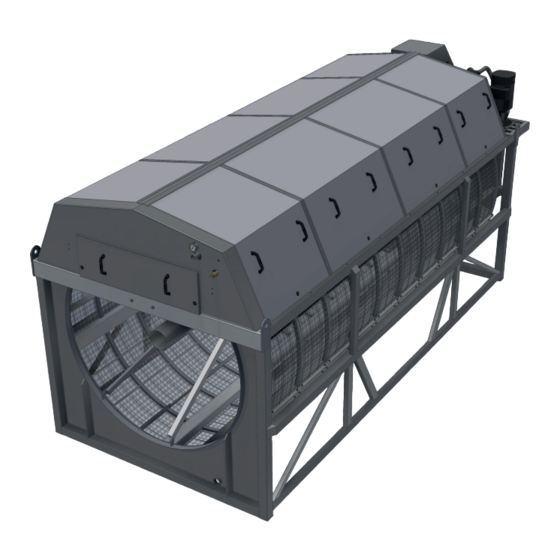
3. HYDROTECH DRUM FILTER 12, 16, & 20 -SERIES 3.1 Overview Figure 3.1 HDF12/16/20/24 series components, filter with stand Operation & maintenance manual, Drum filter HDF 12/16/20/24 -series... - Page 10 Figure 3.2 HDF12/16/20/24, filter with tank Operation & maintenance manual, Drum filter HDF 12/16/20/24 -series...
-
Page 11: Identifying The Filter
3.2 Identifying the filter The filter type, serial number and year of manufacture are stated on the identification plate. The filter type and serial number are also stated on the front of this manual. Figure 3.3 Filter identification plate Figure 3.4 Defitition of filter type Operation &... -
Page 12: Reception And Handling
4. RECEPTION AND HANDLING 4.1 Reception Once the equipment has been delivered and received it must be thoroughly checked for trans- port damage. Document any transport damage before further handling of the equipment. The consignment note, manual and spare part kit are attached to the equipment. Check all parts against the consignment note. -
Page 13: General Installation Instructions
5. GENERAL INSTALLATION INSTRUCTIONS The following requirements must be fulfilled before installation can begin: ⊲ The electrical specifications for the equipment must be in agreement with the applicable spe- cifications for the available power grid. ⊲ The equipment is free from damage (no damage incurred during transport or storage). 5.1 Installation site 5.1.1 Outdoor installation For outdoor installation it is important to pro-... -
Page 14: Electrical Connection
In certain configurations, an external emergency overflow is used in the event of electrical power outages, for example, to avoid subjecting the filter fabric to excessively high pressure differences. 5.3 Electrical connection Electrical connection must be done in accordance with local regulations. Check that the settings on the motor protection device correspond with the motor data (see Appendices A and D). -
Page 15: Start-Up And Operation
6. START-UP AND OPERATION 6.1 Check procedures during start-up 1. Check that the drive unit cover is installed correctly. 2. Turn the pump switch to the OFF (0) position (see F in Figure 6.1). 3. Set the main power switch to the ON (1) position (see J in Figure 6.1). 4. -
Page 16: Automatic Settings
6.2 Automatic settings The control system for HDF16, 20 and 24 series, must always be equipped with a frequency con- verter. This is factory calibrated if delivered from Hydrotech. To perform a soft start of the drive motor, the frequency converter settings must be min. 5 sec “ramp up” and min. 3 sec ”ramp down”. -
Page 17: Level Differences
Figure 6.2 Hydrotech standard control cabinet, type PFC (option). (The control cabinet’s construction is in general adap- ted to the respective application). A. Motor protection pump B. Fuses C. Logic module D. Contactor, pump E. Control relays F. Level relays G. -
Page 18: Operating Mode Hand - Continuous Rotation/Washing
6.2.2 Operating mode HAND – continuous rotation/washing Operation with continuous drum rotation and backwash. In this mode, the water level inside the drum is kept virtually constant. The level sensor and the automatic control system are disabled when the HAND operating mode is selected. 6.2.3 Operating mode AUTO –... -
Page 19: Backwash System
Salt water for example, has high conductivity (setting L). NB. Prior to service, read section 2.7 (Safety instructions). 6.3 Backwash system The system pressure for backwashing must be set to 7-9 bar. Newly connected pipe systems for external wash water should be flushed before they are con- nected to the filter. -
Page 20: Function
7. FUNCTION 7.1 Intended use The filter is designed and manufactured to remove solid particles in unpressurised water flow systems. The filter is not a pressure vessel. 7.2 Non-intended use Unless approved in writing by Hydrotech, the filter must not be used to filter liquids other than water. -
Page 21: Maintenance/Service
8. MAINTENANCE/SERVICE 8.1 Backwash system The most common cause of disruption in the wash water system is nozzle clogging. Clogging is caused by particles in the wash water and/or by e.g. biological fouling in the pipe system. The correct dispersal pattern is shown below for wash water. Clogged nozzles can produce a dif- ferent dispersal pattern. -
Page 22: Self-Cleaning Nozzle
6. Assemble the parts in the reverse order. Make sure the nozzle nut reaches the stop position when turned a ¼ turn, clockwise. 7. Turn the mode selector to the OFF (0) position and the main power switch to the OFF (0) posi- tion. - Page 23 Figure 8.4.1 Lechler nozzle components A. Top nozzle attachment B. Rubber seal C. Top: Nozzle nut, self cleaning (optional) Bottom: Standard nozzle D. Bottom nozzle attachment E. 20 mm screw F. 30 mm screw Operation & maintenance manual, Drum filter HDF 12/16/20/24 -series...
-
Page 24: Wash Water Filter
8.2 Wash water filter A wash water filter should be used to remove particles from the backwash water. Figure 8.4 Wash water filter (option) If the pressure gauge indicates a pressure that is more than 0.5 bar below normal pressure, it is time to clean the wash water filter. -
Page 25: Bearings
8.3 Bearings 8.3.1 Lubrication HDF 12, 16, 20 -series filter: The drum’s centre shaft has slide bearings that must be lubricated. The support wheels have ball bearings that must be lubricated. The bearings should be lubricated per the maintenance chart (see section 8.9). Lubrication stick- ers (see figure 8.5) that specify the lubrication points are affixed to the filter. -
Page 26: Filter Element
8.4 Filter element 8.4.1 High pressure cleaning It may sometimes be necessary to manually clean the filter elements. An indication that manual cleaning is required is increased frequency of automatic backwashing. Manual cleaning can be done using a high pressure washer. NB. - Page 27 If necessary clean the chemical ramp’s nozzles as set out below: 1. Remove the nozzle by turning it a 1/4 turn anticlockwise (see Figure 8.6). 2. Clean the nozzle with compressed air or a plastic brush. Never use a wire brush, metal pins or similar as these can damage the nozzle.
-
Page 28: Replacing Filter Elements
8.4.3 Replacing filter elements 1. Turn the main power switch to the OFF (0) position and lock it in the OFF (0) position with a padlock. 2. Unscrew the nuts that secure the tensioning straps at the drum (see Figure 8.7.a). 3. -
Page 29: Drive Chains, Drives With Roller Chains
8.5 Drive chains, drives with roller chains Drives with roller chains have steel chain wheels; Figure 8.9 shows a roller chain and chain wheel. The filter is powered by a worm gear motor and a chain. See Appendix A and F for technical data. 8.5.1 Checking the drive chain for wear The drive chain must be checked per the maintenance chart (see section 8.9). -
Page 30: Adjusting Drive Chain Tension
8.5.3 Adjusting drive chain tension 1. Stop the filter (turn the main power switch to the OFF (0) position and lock it with a padlock). 2. Loosen the four nuts that hold the worm gear in place (see (1) in Figure 8.9/ Figure 8.10). 3. -
Page 31: Replacing The Drive Chain
8.5.4 Replacing the drive chain 1. Stop the filter (turn the main power switch to the OFF (0) position and lock it with a padlock). 2. Loosen the four nuts that hold the worm gear in place. See (1) in Figure 8.9/ Figure 8.10. 3. -
Page 32: Drive Chain, Drive With Chain Type H78
8.6 Drive chain, drive with chain type H78 Drives with chain type H78 have plastic chain wheels; Figure 8.11 shows chain type H78 and chain wheels. The filter is powered by a worm gear motor and a chain. See Appendix A and F for tech- nical data. -
Page 33: Adjusting Drive Chain Tension
8.6.3 Adjusting drive chain tension 1. Stop the filter (turn the main power switch to the OFF (0) position and lock it with a padlock). 2. Loosen the four nuts that hold the worm gear in place (see Figure 8.12). 3. -
Page 34: Replacing The Drive Chain
8.6.4 Replacing the drive chain 1. Stop the filter (turn the main power switch to the OFF (0) position and lock it with a padlock). 2. Loosen the four nuts that hold the worm gear in place; see Figure 8.12. 3. -
Page 35: Maintenance Chart
8.9 Maintenance chart The maintenance interval shown in the table below is the maximum allowed time interval during typical service conditions. Note! Your specific service conditions may differ from what Hydrotech considers to be typical conditions. In these cases the time between maintenance needs to be adjusted meet your spe- cific requirements. - Page 36 Check the rubber seal for the inlet between the filter frame and drum for Every 12 months. wear/damage. (Also see section 8.8.) NB. Prior to service, read section 2.7 (Safety instructions). Visually check the support wheel bearings for significant wear. Every 12 months.
-
Page 37: Troubleshooting
9. TROUBLESHOOTING Problem Possible cause Solution 1. The filter does not start A. The water has low conductivity. A. Increase the sensitivity by tur- despite the water level in ning the selector for the level re- the drum having reached lay towards MAX. -
Page 38: Symbols Used On Hydrotech Filters
Symbols used on Hydrotech filters Symbol is displaying equipotential earth bonding points on the filter. Symbol shown at lubrication points on the filter. Read the manual for fur- ther information about lubrication. Symbol displaying moving parts. Neg- ligence to comply with safety regula- tions may lead to injury. -
Page 39: Manuals & Technical Information
Manuals & technical information For further technical information please visit http://technomaps.veoliawatertechnologies.com/ hydrotech/en/. Click on ”Manuals & technical information” in the list on the left side. Hydrotech microscreen filters webpage Select the product you want more information about and it will open a Pdf in a new tab. You can also find information regarding products used on Hydrotech filters, e.g. - Page 40 Hydrotech AB A Veolia Solutions & Technologies Company Mejselgatan 6 235 32 Vellinge Sverige Telefon: +46 (0)40 - 42 95 30 Fax: +46 (0)40 - 42 95 31 E-mail: mailbox@hydrotech.se Hemsida: www.hydrotech.se Copyright © All rights reserved...
Need help?
Do you have a question about the HYDROTECH 12 Series and is the answer not in the manual?
Questions and answers