Table of Contents
Advertisement
Advertisement
Table of Contents

Subscribe to Our Youtube Channel
Related Manuals for Veolia Hydrotech Discfilter HPF2200 Series


Summary of Contents for Veolia Hydrotech Discfilter HPF2200 Series
- Page 1 Discfilter HPF2200 - series , PFLC Operation and maintenance manual...
-
Page 2: Table Of Contents
2.2 CE marking 2.3 Conversion 2.4 Personnel requirements 2.5 Emergency stop 2.6 Electrical safety 2.7 Safety instructions 3. HYDROTECH DISCFILTER HPF2200 SERIES 3.1 Reception 3.2 Storage 3.3 Overview 3.3.1 HPF2200 type 1, filter with tank 3.3.2 HPF2200 type 2, filter without tank 3.4 Identifying the filter... - Page 3 4.4 Equipotential bonding 4.5 Checking drum rotation 4.6 Pipe connections 5. START UP AND OPERATION 5.1 Check procedures during start-up 5.2 Automatic settings 5.2.1 Level differences 5.2.2 Operating mode AUTO – Automatic level control 5.2.3 Operating mode REMOTE – Remote control 5.2.4 Service mode HAND 5.3 Backwash system 6.
- Page 4 7.4.2 Chemical cleaning of filter panels 7.4.4 Changing filter panels 7.5 Drive chain 7.5.1 Checking and tensioning the drive chain 7.5.2 Using the chain tensioner to achieve correct tension 7.5.3 Replacing the drive chain 7.6 Drive unit 7.7 Inlet gasket 7.7.1 Checking the inlet gasket 7.7.2 Replacing the inlet gasket 7.8 Lifting the drum...
-
Page 5: Introduction
1. INTRODUCTION This manual contains instructions for the operation and maintenance of Hydrotech Discfilters in the HPF2200 series with PFLC automation. Pay attention to all warning symbols that appear in this manual. If this information is ignored it may result in serious personal injury and/or damage to equipment. The manual must always be available to the personnel working with the equipment. -
Page 6: Safety Instructions
2. SAFETY INSTRUCTIONS Hydrotech Discfilters in the HPF2200 series are designed for safe operation provided they are in- stalled correctly and used in accordance with the enclosed instructions. The equipment must be installed correctly and adapted in accordance with local regulations. This equipment is designed for use by one or more operators. -
Page 7: Conversion
2.3 Conversion The CE marking does not include any components that are not approved by Hydrotech AB and which are used in conversion/reconstruction of the equipment. The warning symbols and CE marking must be attached where they are fully visible. If any part of the equipment with a warning symbol is replaced, a new symbol must be attached in the same position. -
Page 8: Safety Instructions
2.7 Safety instructions The filter is activated by turning the main power switch to the ON (1) position and then selecting AUTO, REMOTE or HAND with the mode selector on the front of the control cabinet. NB See instructions in section 5.1. Turn the main power switch to the OFF (0) position and lock it with a padlock before perfor- ming any work on the filter. -
Page 9: Hydrotech Discfilter Hpf2200 Series
3. HYDROTECH DISCFILTER HPF2200 SERIES 3.1 Reception Once the equipment has been delivered and received it must be checked for transport damage. Document any transport damage before further handling of the equipment. The consignme- nt note, manual and spare part kit are attached to the equipment. Check all parts against the consignment note. -
Page 10: Overview
3.3 Overview 3.3.1 HPF2200 type 1, filter with tank NB Also see section 3.3.2 (HPF2200 type 2, filter without tank) where several filter parts are shown. Figure 3.1 Hydrotech Discfilter in HPF2200 series type 1 (side view). A. Inlet side B. - Page 11 Figure 3.3 Hydrotech Discfilter in HPF2200 series type 1 (outlet side). A. Drain valve B. Bypass valve for nozzle check C. Manometer D. Lubrication point E. Shut off valve for backwash pipe F. Pressure transmittor - dry running protection for pump G.
-
Page 12: Hpf2200 Type 2, Filter Without Tank
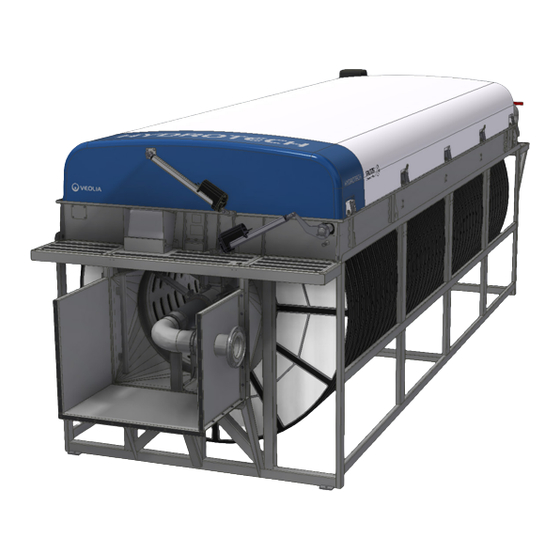
3.3.2 HPF2200 type 2, filter without tank Figure 3.5 Hydrotech Discfilter in HPF2200 series type 2 (side view). A.Inlet side B. Inlet passage C. Filter cover D. Outlet side Figure 3.6 Hydrotech Discfilter in HPF2200 series type 2 (inlet side). A. - Page 13 Figure 3.7 Hydrotech Discfilter in HPF2200 series type 2 (outlet side). A. Manometer B. Bypass valve for nozzle check C. Shut off valve for nozzle check D. Pressure transmittor - dry running protection for pump E. Strainer F. Linear actuator for opening filter cover G.
-
Page 14: Identifying The Filter
3.4 Identifying the filter Filter type, serial number and year of manufacture are stated on the marking plate. The filter type and serial number are also stated on the front of this manual. Figure 3.8 Filter marking plate. 3.4.1 Definition of filter type Figure 3.9 Definition of filter type. -
Page 15: General Installation Instructions
4. GENERAL INSTALLATION INSTRUCTIONS 4.1 Lifting the equipment ⊲ A forklift truck with long forks must be used when lifting filters in wooden crates. ⊲ Filters with a tank can be lifted using a crane or overhead crane by using the filter’s lifting lugs, or with a forklift truck. - Page 16 ⊲ Filters without a tank can be lifted using a crane or overhead crane by using the filter’s lifting lugs or by the use of a forklift. Figure 4.2 Shows how lifting devices are attached (filter without tank). Operation and maintenance, Discfilter HPF2200-series PFLC...
-
Page 17: Installation Site
4.2 Installation site 4.2.1 Outdoor installation In the event of outdoor installation it is important to protect the filter panels against direct sun- light, as heat and UV radiation otherwise can cause damage to the filter panels. The same applies to the control panel touch screen. -
Page 18: Equipotential Bonding
4.4 Equipotential bonding The Hydrotech Discfilter and associated equipment should be protected with a suitable system for equipotential bonding. This is very important to prevent galvanic corrosion. Ideally use a ca- ble with a cross section of 10–16 mm2. The cable should be connected to the same electrical potential as the drive system. -
Page 19: Start Up And Operation
5. START UP AND OPERATION 5.1 Check procedures during start-up 1. Check that the drive unit cover is installed correctly. 2. Set the mode selector to the HAND position (see F in Figure 5.2). 3. Set the main power switch to the ON (1) position (see I in Figure 5.2). 4. -
Page 20: Automatic Settings
5.2 Automatic settings The control system for the HPF2200 series must be equipped with a frequency converter on the drive unit. This is factory calibrated if delivered from Hydrotech. To perform a soft start of the drive motor, the frequency converter settings must be min. 5 sec “ramp up” and min. 3 sec ”ramp down”. -
Page 21: Level Differences
5.2.1 Level differences The maximum permitted difference between the water levels inside and outside the drum is 250 mm during normal operation (see Figure 5.4). The recommended level difference is 100– 200 mm. If an even flow after the filter is required, the filter must be run with a small level difference. -
Page 22: Service Mode Hand
5.2.4 Service mode HAND HAND is only a service mode. In order to operate the filter in HAND mode, the following steps must be implemented: 1. Turn the mode selector shown in Figure 5.2 to the HAND position. 2. Once the mode selector has been turned to HAND, “HAND”... -
Page 23: Function
6. FUNCTION 6.1 Intended use The filter is designed and manufactured to remove solid particles in unpressurised water flow systems. The filter is not a pressure vessel. 6.2 Non-intended use Unless approved in writing by Hydrotech, the filter must not be used to filter liquids other than water. -
Page 24: Maintenance/Service
7. MAINTENANCE/SERVICE 7.1 Backwash system The most common cause of operating disruptions in the backwash system is clogged nozzles. Clogging is caused by particles in the wash water and/or by e.g. biofouling in the pipe system. 7.1.1 Servicing conventional nozzles 1. - Page 25 8. Check whether any of the nozzles are clogged by checking whether water runs through them. Clogged nozzles are cleaned as follows: Figure 7.3 Nozzle components. 9. Remove the nozzle nut by turning it a ¼ turn anticlockwise. Exercise care not to lose the rubber seal.
-
Page 26: Cleaning The Hydrotech Strainer
7.2 Cleaning the Hydrotech strainer NB Prior to servicing, read section 2.7. If the pressure gauge indicates a pressure that is more than 0.5 bar below normal pressure, it’s time to clean the Hydrotech strainer. 1. Turn the main power switch to the OFF (0) position and lock with a padlock. 2. -
Page 27: Bearings
7.3 Bearings NB Prior to servicing, read section 2.7. Stickers indicating the lubrication points are attached to the filter, see Fi- gure 7.6. Figure 7.6 7.3.1 Lubrication of swivel Figure 7.7 Location of the swivel. The swivel makes up the bearing between the backwash pipe and the connecting pipe for the backwash water (see Figure 7.7 &... -
Page 28: Checking Drum Bearing Wear
7.3.3 Checking drum bearing wear 1. Turn the main power switch to the OFF (0) position and lock with a padlock. 2. Drain the chamber/filter tank. 3. Check the drum bearings with respect to wear. If the distance between the bearing housing (A) and the shaft (B) is less than 22 mm (see Figure 7.8), the drum bearing must be replaced. -
Page 29: Filter Panels
7.4 Filter panels NB Prior to servicing, read section 2.7. 7.4.1 Additional cleaning Additional cleaning of the filter panels may be necessary. The need for additional cleaning be- comes clear if the frequency of automatic backwash starts increases. Additional cleaning can be chemical cleaning or cleaning with a high pressure washer. -
Page 30: Chemical Cleaning Of Filter Panels
7.4.2 Chemical cleaning of filter panels Long-term clogging of the filter media can be caused by, among other things, iron, calcium or organic fouling. This clogging can normally be removed through chemical cleaning. Three proven products that do not affect the life of the filter media are dilute hydrochloric acid (HCl), dilute sodium hypochlorite (NaClO) and dilute sodium hydroxide (NaOH). - Page 31 If necessary clean the chemical ramp nozzles as described below: Figure 7.13 a) Location of the chemical spraybar (highlighted in blue) seen from the inlet side of the filter. 1. Turn the main power switch to the OFF (0) position and lock with a padlock. 2.
-
Page 32: Changing Filter Panels
7.4.4 Changing filter panels When replacing the filter panels it is important to maintain the balance of the drum. Remove/ refit every other filter panel. This prevents unintentional rotation of the drum and reduces the load on the drive chain and gearbox. Figure 7.14 Correct way of changing filter panels. - Page 33 5. Undo the filter segment cover screw and remove the cover, see Figure 7.18). Figure 7.18 The filter segment cover is removed. 6. Pull out the filter panel (see Figure 7.19). Figure 7.19 The filter panel is pulled out. Operation and maintenance, Discfilter HPF2200-series PFLC...
- Page 34 7. Insert a new filter panel and press in until it touches the bottom. NB Filter panels with steel frames must be po- sitioned with the filter cloth facing inwards (see Figure 7.20). Incorrect installation of the filter panels can cause damage to the filter segments. 8.
-
Page 35: Drive Chain
7.5 Drive chain NB Prior to servicing, read section 2.7. The filter is equipped with a chain drive. For technical data, see Appendices A and D. 7.5.1 Checking and tensioning the drive chain Figure 7.21 Displaying the correct slack of the drive chain and position of the tensioner. 1. -
Page 36: Using The Chain Tensioner To Achieve Correct Tension
7.5.2 Using the chain tensioner to achieve correct tension 1. Turn the main power switch to the OFF (0) position and lock with a padlock. 2. Remove the motor cover to access the chain. Figure 7.22 The three screws holding the flooring tile highlighted in blue. 3. - Page 37 Figure 7.23 Detailed view of the chain tensioner. 4. Loosen the two screws to the left in figure 7.22. The screws are loosend enough when the chain tensioner is able to move freely. Be careful when loosening the screws so that the bracket under- neath the beam dont fall off.
-
Page 38: Replacing The Drive Chain
7.5.3 Replacing the drive chain 1. Turn the main power switch to the OFF position and lock with a padlock. 2. Get maximum amount of slack on the drive chain by using the chain tensioner. For further information of how to use the chain tensioner, read section 7.5.2. 3. -
Page 39: Replacing The Inlet Gasket
7.7.2 Replacing the inlet gasket 1. Turn the main power switch to the OFF (0) position and lock with a padlock. 2. Lower the water level in the filter until the whole inlet gasket is accessible. 3. Note how the inlet gasket is fitted before it is dismantled. 4. -
Page 40: Use Of The Rear Drum Lifter
The drum lifter is operated by tightening the screw (the screw marked blue, in figure 7.8.2). This will push on the center of the inside ring of the drum, lifting it vertically. Figure 7.8.2 The drum is lifted by tightening the highlighted screw. 7.8.1 Use of the rear drum lifter The location of the rear drumlifter is displayed in figure 7.8.3 below. -
Page 41: Lifting The Drum On Filters With Tank
The rear drum lifter is opeated in the same way as the front drum lifter, but instead of one screw placed in the center of the drum, there is now two screws lifting the drum. Tighten one screw at the time, and lift the drum slowly by taking turns on the two screws so that the drum is being held close to the centreline of the filter during the entire process. -
Page 42: Maintenance Schedule
8. MAINTENANCE SCHEDULE Check/Action Maintenance interval Check whether the wash water filter is clogged. See The interval is based on experience from the app- section 7.2. lication in question. (When the backwash water pressure drops 0.5 bar below the normal value.) Check the filter panels for clogging and damage. -
Page 43: Symbols Used On Hydrotech Filters
Symbols used on Hydrotech filters Symbol is displaying equipotential earth bonding points on the filter. Symbol shown at lubrication points on the filter. Read the manual for fur- ther information about lubrication. Symbol displaying moving parts. Neg- ligence to comply with safety regula- tions may lead to injury. -
Page 44: Manuals & Technical Information
Manuals & technical information For further information regarding Hydrotech filters or any other product used together with Hydrotech filters, please visit www.hydrotech.se. Click on ”Manuals & technical information”. Locate the desired product manual and select manual by clicking on one of the language options. - Page 45 Hydrotech AB A Veolia Solutions & Technologies Company Mejselgatan 6 235 32 Vellinge Sweden Telephone: +46 (0)40 - 42 95 30 Fax: +46 (0)40 - 42 95 31 E-mail: mailbox@hydrotech.se Web: www.hydrotech.se Copyright © All rights reserved Operation and maintenance, Discfilter HPF2200-series PFLC...
Need help?
Do you have a question about the Hydrotech Discfilter HPF2200 Series and is the answer not in the manual?
Questions and answers