Table of Contents
Advertisement
Advertisement
Table of Contents

Subscribe to Our Youtube Channel
Related Manuals for Veolia Hydrotech Discfilter HSF 26-2F Series


Summary of Contents for Veolia Hydrotech Discfilter HSF 26-2F Series
- Page 1 Discfilter HSF 26 - 2-3F series with PFLC Operation and maintenace manual...
-
Page 2: Table Of Contents
LIST OF CONTENTS 1. INTRODUCTION 2. SAFETY INSTRUCTIONS 2.1 Warning symbols 2.2 CE marking 2.3 Conversion 2.4 Demands on personnel 2.5 Emergency stop 2.6 Electrical safety 2.7 Safety instructions 3. HYDROTECH DISCFILTER HSF2600 SERIES 3.1 Overview 3.2 Identifying the filter 4. - Page 3 5.3 Filtration and backwash process 6. MAINTENANCE/SERVICE 6.1 Filter cover 6.1.1 Hinge 6.1.2 Operating the filter cover 6.2 Extend the backwash pipe 6.3 Backwash system 6.3.1 Servicing nozzles 6.4 Backwash pipe position 6.4.1 Checking backwash pipe position 6.4.2 Checking backwash pipe position 6.5 Cleaning the backwash water filter 6.6 Bearings 6.6.1 Lubrication of swivel...
- Page 4 6.10 Inlet seal 6.10.1 Checking inlet seal. 6.10.2 Replacing the inlet seal 7. MAINTENANCE SCHEDULE Symbols used on Hydrotech filters Manuals & technical information Operation and maintenance, Discfilter HSF2600 - 2,3 series with PFLC...
-
Page 5: Introduction
1. INTRODUCTION This manual contains instructions for the operation of Hydrotech Discfilters in the HSF2600 se- ries, types 2F and 3F (filter with frame). Pay attention to all warning symbols that appear in this manual. If this information is ignored it may result in serious personal injury and/or damage to equipment. -
Page 6: Safety Instructions
2. SAFETY INSTRUCTIONS Hydrotech Discfilters in the HSF2600 series are designed for safe operation provided that they are installed correctly and used in accordance with the enclosed instructions. The equipment must be installed correctly and adapted in accordance with local regulations. The machine equipment is intended for use by multiple operators. -
Page 7: Demands On Personnel
the equipment with a warning symbol is replaced, a new symbol must be attached in the same position. Damaged symbols and CE markings must be replaced immediately. 2.4 Demands on personnel Only personnel trained for the equipment and conversant with local regulations may perform service and maintenance, in order to avoid personal injury and damage to the equipment. - Page 8 must be fenced in. The filter can start rotating without warning if automatic control is activated. Moving parts must not be touched. Safety guards are fitted around the power transmission. Make sure these are secured and cor- rectly fitted. Spray from the backwash water may contain harmful substances. Measured noise levels from the filter are less than 74 dB(A).
-
Page 9: Hydrotech Discfilter Hsf2600 Series
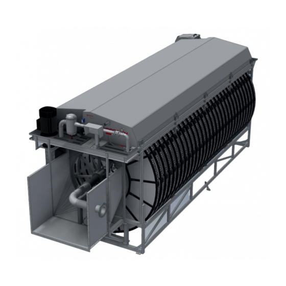
3. HYDROTECH DISCFILTER HSF2600 SERIES 3.1 Overview Inlet side Inlet passage Filter cover Outlet side Figure 3.1 Hydrotech Discfilter in HSF2600 series type 1F (side view). Figure 3.2 Hydrotech Discfilter in HSF2600 series type 2F (from inlet side). Backswash pump (option) Sludge trough Backwash water filter Holder for level sensor, inlet water... - Page 10 Figure 3.3 Hydrotech Discfilter in HSF2600 series type 2F (from inlet side). Actuator for backwash system servicing Backwash pipe drive Actuator for opening cover Drive chain Drive unit Drum bearing, outlet side Lubrication point Drum Two drum lifters are supplied unassembled for each installation, see Figure 3.4. These are only used when servicing drum bearings.
-
Page 11: Identifying The Filter
3.2 Identifying the filter Filter type, serial number and year of manufacture are stated on the marking plate. The filter type and serial number are also stated on the front of this manual. Figure 3.5 Filter marking plate Definition of filter designation: Operation and maintenance, Discfilter HSF2600 - 2,3 series with PFLC... -
Page 12: Start Up And Operation
4. START UP AND OPERATION 4.1 Check procedures during start-up 1. Check that the drive unit cover is installed correctly. 2. Set the mode selector to the HAND position (see F in Figure 4.2) 3. Set the main power switch to the ON (1) posi- tion (see I in Figure 4.2) 4. -
Page 13: Automatic Settings
4.2 Automatic settings The control system for the HSF2600 series must always be equipped with a frequency converter for the drive unit. This is factory calibrated if delivered from Hydrotech. To perform a soft start of the drive motor, the frequency converter settings must be min. 5 sec “ramp up” and min. 3 sec “ramp down”. -
Page 14: Level Differences
4.2.1 Level differences maximum permitted difference between the water levels inside and outsi- de the drum is 250 mm during normal ope- ration (see Figure 4.3). The recommended level difference is 100-200 mm. If an even flow after the filter is required, the filter must be run with a small level dif- ference. -
Page 15: Service Mode Hand
4.2.4 Service mode HAND HAND is only a service mode. In order to operate the filter in HAND mode, the following steps must be implemented: 1. Turn the mode selector shown in Figure 4.2 to the HAND position. 2. Once the mode selector has been turned to HAND, “HAND”... -
Page 16: Function
5. FUNCTION 5.1 Intended use The filter is designed and manufactured to remove solid particles in unpressurised water flow systems. The filter is not a pressure vessel. 5.2 Non-intended use Unless approved in writing by Hydrotech, the filter must not be used to filter liquids other than water. -
Page 17: Maintenance/Service
6. MAINTENANCE/SERVICE This chapter describes how maintenance and servicing is to be carried out. Chapter 7 describes how often the various components require servicing. 6.1 Filter cover NOTE! Prior to servicing, read section 2.7. The filter cover for the Hydrotech Discfilter HSF2600 series is controlled from the operator panel and can be opened from two directions, depending on which side of the filter needs to be accessed. -
Page 18: Operating The Filter Cover
6.1.2 Operating the filter cover 1. In order to operate the filter cover, the mode selector shown in Figure 6.3 must be in the “HAND” position. When in HAND mode, “HAND” is shown in the operator panel main menu, see Figure 6.4 below. 2. -
Page 19: Extend The Backwash Pipe
6.2 Extend the backwash pipe NOTE! Prior to servicing, read section 2.7. 1. Turn the mode selector to “HAND” and lift the filter cover on the backwash pipe side, see section 6.1. 2. When the cover is fully opened on the back- wash pipe side, B3.2, B3.3 and B7.2, as shown in Figure 6.7 will be on. - Page 20 Figure 6.10 Service Cover & Spray bar menu. Figure 6.11 Service menu. 6. Select “Start” in the “Pump” window, see Figure 6.12. 7. Close the main valve (A), see Figure 6.9. 8. Adjust the backwash water flow using the by- pass valve so that there is a small but constant flow through the nozzles.
- Page 21 Figure 6.13 Hydrotech backwash nozzles. A. Top nozzle attachment B. Rubber seal C. Top: Nozzle nut, self cleaning (optional) Bottom: Standard nozzle D. Bottom nozzle attachment E. 20 mm screw F. 30 mm screw 19. Close the filter cover 20. Start operation again as set out in section 4.1. Operation and maintenance, Discfilter HSF2600 - 2,3 series with PFLC...
-
Page 22: Backwash Pipe Position
6.4 Backwash pipe position NOTE! Prior to servicing, read section 2.7. 6.4.1 Checking backwash pipe position 1. Turn the mode selector to “HAND” and lift the filter cover on the backwash pipe side, see section 6.1. 2. Select “Start” for the drum on the operator panel, see Figure 6.14. -
Page 23: Checking Backwash Pipe Position
6.4.2 Checking backwash pipe position 1. Turn the main power switch to the OFF (0) position and lock with a padlock. 2. Undo the nut (B), see Figure 6.16. 3. Adjust the position of the backwash pipe using the screw (A). Figure 6.16 Screw and nut for adjustment of backwash pipe position and backwash pipe safety stop. -
Page 24: Cleaning The Backwash Water Filter
6.5 Cleaning the backwash water filter NOTE! Prior to servicing, read section 2.7. If the pressure gauge indicates a pressure that is more than 0.5 bar below normal pressure, it’s time to clean the backwash water filter. 1. Turn the main power switch to the OFF (0) position and lock with a padlock. 2. -
Page 25: Bearings
6.6 Bearings NOTE! Prior to servicing, read section 2.7. 6.6.1 Lubrication of swivel The swivel, the backwash pipe bearing, is located under the cover and connects the piping with the backwash pipe, see Figure 6.18. When lubricating the swivel, the instructions below must be followed: 1. -
Page 26: Checking Drum Bearing Wear
6.6.3 Checking drum bearing wear 1. Turn the main power switch to the OFF (0) position and lock with a padlock. 2. Drain the filter basin. 3. Check the drum bearings for wear. If the distance between the bearing housing (A) and the shaft (B) is less than 29 mm (see Figure 6.20), the drum bearing must be replaced. -
Page 27: Filter Panels
6.7 Filter panels NOTE! Prior to servicing, read section 2.7. 6.7.1 High pressure cleaning It may be necessary to manually clean the filter panels. It may be obvious that manual cleaning is required as automatic backwashing starts on a more frequent basis. Manual cleaning can be done using a high pressure washer. -
Page 28: Chemical Cleaning Of Filter Panels
6.7.2 Chemical cleaning of filter panels Long-term clogging of the filter media can be caused by, among others, iron, calcium or organic fouling. This clogging can normally be removed through chemical cleaning. Three proven pro- ducts that do not affect the life of the filter media are dilute hydrochloric acid (HCl), dilute sodi- um hypochlorite (NaClO) and dilute sodium hydroxide (NaOH). - Page 29 4. Follow the instructions set out in section 4.2.2 of the “Automatic Control System Manual”. 5. Once chemical cleaning has been completed, re-start operation as described in section 4.1. Figure 6.22 Main menu on electrical cabinet operator panel. Operation and maintenance, Discfilter HSF2600 - 2,3 series with PFLC...
-
Page 30: Changing Filter Panels
6.7.3 Changing filter panels It is important to maintain the balance of the drum when changing filter panels. Remove/ refit every other filter panel. This prevents un- intentional rotation of the drum and reduces the load on the drive chain and gearbox. Figure 6.23 Correct way of changing filter panels. - Page 31 Figur 6.27 Montering av filtersegmentets lock. Figur 6.28 Filterpanelernas placering. Operation and maintenance, Discfilter HSF2600 - 2,3 series with PFLC...
-
Page 32: Drive Chain
6.8 Drive chain NOTE! Prior to servicing, read section 2.7. The filter is equipped with a chain drive. For technical data, see Appendices A and D. 6.8.1 Checking the drive chain 1. Turn the mode selector to “HAND” and lift the filter cover on the same side as the drive unit, see section 6.1. -
Page 33: Adjusting Drive Chain Tension
6.8.2 Adjusting drive chain tension Adjust drive chain tension as follows: 1. Turn the main power switch to the OFF (0) position and lock with a padlock. 2. Loosen the four nuts (A). See Figure 6.30. 3. Loosen the nut (B). 4. -
Page 34: Drive Unit
6.9 Drive unit NOTE! Prior to servicing, read section 2.7. For information about the drive unit, see Appendix D. When changing the drive unit oil, the oil should pre- ferably be drained with pump. 6.10 Inlet seal NOTE! Prior to servicing, read section 2.7. 6.10.1 Checking inlet seal. -
Page 35: Maintenance Schedule
7. MAINTENANCE SCHEDULE Check/Action Maintenance interval Check whether the backwash water filter is clogged. The interval is based on experience from the app- See section 6.5. lication in question. (When the wash water press- ure drops 0.5 bar below the normal value.) Check the filter panels for clogging and damage, see Once a week, or at another interval based on ex- section 6.7. -
Page 36: Symbols Used On Hydrotech Filters
Symbols used on Hydrotech filters Symbol is displaying equipotential earth bonding points on the filter. Symbol shown at lubrication points on the filter. Read the manual for fur- ther information about lubrication. Symbol displaying moving parts. Neg- ligence to comply with safety regula- tions may lead to injury. -
Page 37: Manuals & Technical Information
Manuals & technical information For further technical information please visit http://technomaps.veoliawatertechnologies.com/ hydrotech/en/. Click on ”Manuals & technical information” in the list on the left side. Hydrotech microscreen filters webpage Select the product you want more information about and it will open a Pdf in a new tab. You can also find information regarding products used on Hydrotech filters, e.g. - Page 38 Hydrotech AB A Veolia Solutions & Technologies Company Mejselgatan 6 235 32 Vellinge Sverige Telefon: +46 (0)40 - 42 95 30 Fax: +46 (0)40 - 42 95 31 E-mail: mailbox@hydrotech.se Hemsida: www.hydrotech.se Copyright © All rights reserved Operation and maintenance, Discfilter HSF2600 - 2,3 series with PFLC...
Need help?
Do you have a question about the Hydrotech Discfilter HSF 26-2F Series and is the answer not in the manual?
Questions and answers