Table of Contents
Advertisement
Quick Links
• 取扱説明書(以下、本書といいます)の『製品使用上のご注意』の内容をよく理解し、本書をよく読んでか
ら操作してください。
Please understand well the contents of "Cautions on Product Use" of Instruction Manual
(hereinafter referred to as "this manual"), and operate it after often reading this manual.
• 本書はいつでも使用できるよう、大切に保管してください。
Please keep this manual carefully to be able to use it at any time.
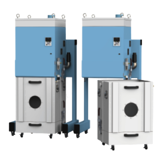
Pulse Dust Collector
チコーエアーテック株式会社
CHIKO AIRTEC CO., LTD.
パルス式集塵機
取扱説明書
Instruction Manual
型式/MODELS
CHP-5000AT3-DSA-UD
日
本
語
(200V)
Advertisement
Chapters
Table of Contents

Related Manuals for CHIKO AIRTEC CHP-5000AT3-DSA-UD


Summary of Contents for CHIKO AIRTEC CHP-5000AT3-DSA-UD
- Page 1 Please understand well the contents of "Cautions on Product Use" of Instruction Manual (hereinafter referred to as “this manual”), and operate it after often reading this manual. • 本書はいつでも使用できるよう、大切に保管してください。 Please keep this manual carefully to be able to use it at any time. チコーエアーテック株式会社 CHIKO AIRTEC CO., LTD.
- Page 2 揮できますよう正しいお取扱いをお願いします。 We greatly appreciate that you have purchased our CBA Series. CHIKO AIRTEC CO., LTD. is working to achieve clean air with compact equipment while utilizing “air technology” effectively. The CHP Series is an energy-saving-type clean box that realizes “air technology” in a compact body.
- Page 4 チコーエアーテック株式会社 CHIKO AIRTEC CO.,LTD. 〒562-0012 大阪府箕面市白島 2-27-24 2-27-24,Hakushima, Minoh, Osaka 562-0012, Japan TEL (81) 072-720-5151 FAX (81) 072-720-5133 URL http://chiko-airtec.jp/...
-
Page 5: Table Of Contents
1.5 その他のご注意 ..........................4 1.6 危険シールの貼付位置 ........................5 第 2 章 各部の名称 ......................6 2.1 付属品 ............................. 6 2.2 装置本体 ............................7 2.2.1 CHP-5000AT3-DSA-UD ......................7 2.3 AT3 パネル ............................8 2.4 ディスプレイ表示 ..........................9 2.4.1 モードについて ......................... 9 2.4.2 停止中の表示 .......................... 9 2.4.3 運転中の表示... - Page 6 6.1.2 ピンアサイン ........................... 31 6.1.3 リモート操作 ........................... 32 6.2 通信機能 ............................32 6.2.1 RS485 通信 ..........................32 6.2.2 イーサネット..........................32 第 7 章 付録 ........................33 7.1 仕様 ............................... 33 7.2 消耗品リスト ........................... 33 7.3 電気回路図 ............................ 34 7.3.1 CHP-5000AT3-DSA-UD ......................34...
-
Page 7: 第1章 製品使用上のご注意
第 1 章 製品使用上のご注意 第1章 製品使用上のご注意 日 本 語 1.1 安全に関する表記 この取扱説明書には、使用時の注意事項が下記の記号とともに記載されています。 必ずお読みください。 記 号 意 味 正しく使用しない場合、取扱者が死亡または重傷を負う危険性がある注意事項が記載され 警 告 ています。 正しく使用しない場合、取扱者が傷害を負う危険性や本装置を損傷する恐れがある注意 注 意 事項が記載されています。 行ってはいけない「禁止」の内容です。 必ず実行する「強制」の内容です。 1.2 運搬・保管・輸送時のご注意 • 運搬は、二人以上で行って下さい。 警 告 落下などにより、けがをする恐れがあります。 • 輸送・保管は安全な場所で、温度-10℃~60℃ 湿度 80%以下の範囲としてくだ 注 意 さい。... -
Page 8: 運転時のご注意
第 1 章 製品使用上のご注意 1.4 運転時のご注意 • 次の物質は吸引しないでください。 引火性物質 ....ガソリン・シンナー・ベンジン・灯油・塗料など。 爆発性粉塵 ....アルミニウム・マグネシウム・チタン・亜鉛・エポキシなど 火花を含んだ粉塵 ..高速切断機・グラインダー・溶接機などから発生する火 花を含んだ粉塵。 火種 ......たばこ・油・薬品などの液体 その他 ...... 水・油・薬品などの液体 • 引火性・爆発性・腐食物質の霧・煙・ガスが滞留している場所や、これらの付近 警 告 で使用しないでください。 • 接続は、確実に行い、ケーブルを無理に曲げたり、引っ張ったりしないでくださ い。 火災・感電の原因になります。 • 本機の仕様と異なる電源で使用しないでください。 • 粉塵爆発のおそれのない乾いた粉塵の吸引に使用してください。 • アース線は必ず接続して使用してください。 • 運転中は移動させないでください。 •... -
Page 9: 危険シールの貼付位置
第 1 章 製品使用上のご注意 1.6 危険シールの貼付位置 日 本 語 高電圧警告シール 高温警告シール ネームプレート ① 高電圧警告シール ② ③ ネームプレート ② 分解禁止シール 分解禁止シール 高電圧警告シール 高温警告シール ネームプレート ① ② 分解禁止シール ③ CMN015-005 原本の翻訳 (Translation of the original instructions) -
Page 10: 第2章 各部の名称
第 2 章 各部の名称 第2章 各部の名称 2.1 付属品 ① ② ③ ④ ⑤ ⑥ ⑦ 番号 名称 働き 数量 1 次フィルタ ① 粉塵やヒュームを収集・吸着します。 ② バルブブースター 1次フィルタ内のパルスエアーを整流させます。 フィルタ表面に積層させ、フィルタ表面へのヒュームの付着を ③ ゼオライト 軽減させます。 ④ ブロア冷却用排気フィルタ 排気をクリーンにします。 ⑤ フィルタレギュレータ 圧縮空気の圧力を調整します。(設定値:0.45~0.55MPa) ⑥ 昇降用工具 本体をジャッキアップ・ダウンさせるための工具 ⑦ スタートアップガイド... -
Page 11: 装置本体
第 2 章 各部の名称 2.2 装置本体 日 本 語 2.2.1 CHP-5000AT3-DSA-UD ① ⑧ ⑨ ② ③ ④ ⑭ ⑩ ⑤ ⑪ ⑫ ⑥ ⑬ ⑦ ⑫ 番号 名称 働き ① 排気口 排気ダクトを接続します。 AT3 パネル(操作パネル) ② 本機を操作します。 ③ 電池ボックス ボタン電池を収納しています。 ④... -
Page 12: At3 パネル
第 2 章 各部の名称 2.3 AT3 パネル ① ② ③ ④ ⑨ ⑤ ⑤ ⑧ ③ ⑥ ⑦ 番号 名称 働き 有機 EL(OLED) 運転状態や各種設定内容を表示します。 ① エラー・警告発生時は、エラー・警告 No.を表示します。 ディスプレイ 能力レベルを緑色のランプで表示します。(レベル 1~7) ② 能力レベルランプ 停止中、運転中は、ディスプレイの表示内容を切り替えます。 「 ディスプレイ表示」( ページ) ③ ↑/↓ボタン モードセレクトモード時は、設定項目の切り替えと設定する数値データを変更 します。 「第... -
Page 13: ディスプレイ表示
第 2 章 各部の名称 2.4 ディスプレイ表示 日 本 語 2.4.1 モードについて 通常モード モードセレクトモード 主電源スイッチ 停止中 ページ モードセレクトボタン 初期圧登録クリア ページ OFF ボタン ON ボタン OFF ボタン 3 秒押し 初期圧登録 運転中 ページ ENTER ボタン 3 秒押し 2.4.2 停止中の表示 ↑/↓ボタンで表示を切り替えることができます。 Ver*.** ID.** プログラムバージョン、RS485 通信用局番 Battery ***% 電池残量... -
Page 14: 運転中の表示
第 2 章 各部の名称 2.4.3 運転中の表示 ↑/↓ボタンで表示を切り替えることができます。 **.**kPa 外部圧 **.**kPa 吸込圧 **.**kPa 差圧 **.**kPa 排気圧 Blower ***.*℃ ブロア周辺温度 モータ回転数 Motor *****rpm 現在運転中のモータの回転数を表示します。 積算稼働時間(リセット可) Runtime ******h リセット後からの稼働時間を表示します。 ページ 積算稼働時間リセットモード( ) 実働時間(リセット不可) Total ******h トータルの稼働時間を表示します。... -
Page 15: 第3章 運転
第 3 章 運転 第3章 運転 日 本 語 3.1 運転前の準備 3.1.1 設置 ■ 設置方法 • 運搬や設置は、二人以上で行って下さい。 注 意 落下などにより、けがをする恐れがあります。 • 設置完了後、必ずストッパーで固定して下さい。 吊位置 設置完了後、ストッパー4 カ所で固定する事。 ■ 設置場所 使用上安全および本機の性能を十分に発揮させるため、下記の条件を満たす場所に設置してください。 項 目 内 容 0℃~+40℃の範囲 周 囲 温 度 80%RH 以下の範囲(結露のないこと) 周 囲 湿 度 雰... - Page 16 第 3 章 運転 • ボタン電池は電源が OFF のときに消費されます。 • 電源 ON 時(1μA 以下)、電源 OFF 時(40~50μA) メ モ • 電池寿命(参考値:約 2 年)は、使用状況によって変わります。目安としてください。 ■ フィルタレギュレータの取り付け フィルタレギュレータ設置箇所に取り付けます。 レギュレータ内に合成油・有機化合物・化学薬品・切削油及びそのミスト等を付着させ 注 意 ないでください。...
-
Page 17: 配線・配管
第 3 章 運転 3.1.2 配線・配管 日 本 ■ 配線 語 • 接続は、確実に行い、ケーブルを無理に曲げたり、引っ張ったりしないでくださ い。 火災・感電の原因になります。 警 告 • 本機の仕様と異なる電源で使用しないでください。 • アース線は必ず接続して使用してください。 • 電圧低下の原因になりますので、タコ足配線にしないでください。 注 意 電圧が降下すると正常に動作しなくなり、故障の原因になります。 本機の電源は、三相電源です。 供給電圧の許容範囲は、±10%です。 電源端子台 BOX のネジを取り外し フタを外します。 電源ケーブルを本機の電源端子台に接続しま す。 電源ケーブルの電源側を電源に接続します。 CMN015-005 原本の翻訳 (Translation of the original instructions) -
Page 18: 保護機能
第 3 章 運転 ■ 配管 吸気配管(別途ご準備)を吸込み口フランジに 接続します。 吸込み口 φ8 のエアーチューブをフィルタレギュレータに 接続します。 0.45MPa~0.55MPa 推奨エア圧 3.1.3 保護機能 フィルタが目詰まりしたまま運転を続けると下記の様な保護機能が働きます。保護機 注 意 能が働いた時点でブロア等にダメージが及ぶ可能性があります。 直ちにフィルタ及び各部の点検を行ってください。 ■SP(吸込圧)上昇 フィルタ目詰まり等により、16.5kPa 付近に達すると、リリーフバルブが作動します。 また、19kPa 付近で電流値は 26.5A に達し、この状態が 10 秒以上続くと強制停止します。 ■温度上昇 モータ温度が 80℃を超えると、ディスプレイに WARN1 が表示されます。 さらに、90℃に達すると ERR04 が表示され、強制停止します。... -
Page 19: 初期圧登録
第 3 章 運転 3.2 運転 日 本 語 電源を ON にします。 ディスプレイにプログラムバージョンと Ver*.** ID.** RS485 通信用の ID 番号が表示されます。 AT3 パネルの ON ボタンを押します。 装置の運転が開始されます。 異常音がないことと、適切な吸引であること を確認します。 能力レベルランプ ←/→ボタンで吸引レベルを設定します。 能力レベルランプ(1~7)で吸引能力が表示 されます。 ←/→ボタン • 適切な配管で運転してください。 重 要 配管はできるだけ短くし、配管口径は狭くしすぎないでください。 3.3 初期圧登録 初期登録した差圧からフィルタ目詰まりによる風量低下を判定し、風量不足(WARN4)としてお知らせします。 次の手順で、初期圧力を登録してください。 本機を配線、配管します。... -
Page 20: 第4章 各種設定(モードセレクトモード
第 4 章 各種設定(モードセレクトモード) 第4章 各種設定(モードセレクトモード) 4.1 モードセレクトモードでの画面遷移 停止中に MODE SELECT ボタンを押すとモードセレクトモードに移行します。 ↑/↓ボタンで設定項目を切り替えます。 通信フォーマット設定モード [Com Setting] ( ページ) 風量不足お知らせタイミング設定モード [Volume Down ST] ( ページ) その他の設定モード [Other Setting] ( ページ) エラー履歴モード [Error Data] ( ページ) 4.2 通信フォーマット設定モード(通信機能装備時) シリアル通信フォーマットの以下の項目を設定します。 設定した内容は電源 OFF→ON での再起動後に有効になります。 項... -
Page 21: 風量不足お知らせタイミング設定モード
第 4 章 各種設定(モードセレクトモード) ENTER ボタンを押します。 日 設定画面が表示されます。 本 ↑/↓ボタンを押して設定内容を選択します。 語 ENTER ボタンを押して設定内容を決定します。 終了する場合は MODE SELECT ボタンを押して通常モードに戻ります。 4.3 風量不足お知らせタイミング設定モード 風量不足警告(WARN4)を表示させるタイミングを任意で変更できます。 モードセレクトモードに移行します。 ↑/↓ボタンを押して風量不足お知らせタイミング設定モード(“Volume Down ST”)に移行します。 ENTER ボタンを押します。 現在の設定内容が表示されます。 標準出荷設定値は 50%で、“3:Down to 50%”が表示されます。 ↑/↓ボタンを押して 30%~70%の間で選択します。 設定値を下げると風量不足お知らせのタイミングが遅くなり、設定値を上げると早くなります。 ENTER ボタンを押して設定内容を決定します。 終了する場合は MODE SELECT ボタンを押して通常モードに戻ります。 4.4 その他の設定モード... -
Page 22: 時刻合わせモード
第 4 章 各種設定(モードセレクトモード) 4.4.1 時刻合わせモード 日付と時刻を設定します。 モードセレクトモードに移行します。 ↑/↓ボタンを押してその他の設定モード(“Other Setting”)に移行します。 ENTER ボタンを押します。 “Time Adjust”が表示されます。 ENTER ボタンを押します。 日付の設定画面になります。 ↑/↓ボタンを押して数値を変更します。 ENTER ボタンを押して数値を決定します。 年、月、日の順に設定します。 日付が設定されると、時刻の設定画面になります。 ↑/↓ボタンを押して数値を変更します。 ENTER ボタンを押して数値を決定します。 時、分、秒の順に設定します。 終了する場合は、MODE SELECT ボタンを押して通常モードに戻ります。 4.4.2 積算稼働時間リセットモード 積算稼働時間(Runtime)をリセットします。 モードセレクトモードに移行します。 ↑/↓ボタンを押してその他の設定モード(“Other Setting”)に移行します。 ENTER ボタンを押します。 “Time Adjust”が表示されます。 ↑/↓ボタンを押して、表示を“[Runtime Reset]”にします。 ENTER ボタンを押します。... -
Page 23: 設定値リセットモード
第 4 章 各種設定(モードセレクトモード) 4.4.3 設定値リセットモード 日 通信フォーマットと風量不足お知らせタイミングを標準出荷設定値に戻し、積算稼働時間をリセットします。 本 語 モードセレクトモードに移行します。 ↑/↓ボタンを押してその他の設定モード(“Other Setting”)に移行します。 ENTER ボタンを押します。 “Time Adjust”が表示されます。 ↑/↓ボタンを押して、表示を“[Setting Reset]”にします。 ENTER ボタンを押します。 “1:YES”と表示され、設定値をリセットするか確認されます。 リセットする場合は ENTER ボタンを押してください。 再確認のため、“1:START”と表示されます。 ENTER ボタンを押すと設定値がリセットされ、通常モードに移行します。 4.5 エラー履歴モード 4 件分のエラー履歴を確認することができます。 エラー履歴は電源を OFF するとクリアされます。 モードセレクトモードに移行します。 ↑/↓ボタンを押してエラー履歴モード(“Error Data”)に移行します。 ENTER ボタンを押します。 直近で発生したエラーNo と発生したときの積算稼働時間が表示されます。... -
Page 24: 第5章 保守・点検
第 5 章 保守・点検 第5章 保守・点検 • 保守・点検時は必ず電源を切り、コンセントからプラグを抜いて、電路遮断を行っ てください。 • 作業は 2 人以上で行い、必ず保護具を着用してください。 注 意 • 摩耗や破損したフィルタをそのまま使用すると、内部の電気部品が損傷いたしま す。故障、事故の原因を未然に防ぐ為、保守・点検は必ず行ってください。 • フィルタの交換は十分なスペースがある場所で行ってください。 また、フィルタの取り付け時は、裏・表を間違えないでください。 • クリーンルーム外で保護シートを敷いて作業を行ってください。 重 要 • 集塵物によっては、交換時に、粉塵が飛散する場合がございます。保護メガネ・保 護マスクを着用して作業を行って下さい。 5.1 フィルタのメンテナンス・交換 目詰まりした場合、「WARN2」の警告が表示されますので、1 次フィルタを交換してください。 パッキン部に付いたゴミは、ウエス等で綺麗に拭取り、清掃して下さい。 注 意 吸引力低下、粉塵漏れ等といった、トラブルの原因になります。 5.1.1 1次フィルタのメンテナンス・交換 • 1 次フィルタの交換は、十分なスペースがある場所で行ってください。 重... -
Page 25: 1次フィルタの交換・メンテナンス(1本づつ引き上げる場合
第 5 章 保守・点検 ブロア室を 30mm 以上上昇させてください。 日 本 語 1 次フィルタ室を手前に引き出します。 洗浄後及び交換後のフィルタを取り付けの際、締め付けが均一でない場合や締め付 けが緩い場合は、ゼオライトが漏れる可能性があります。 注 意 又、年次劣化により 1 次フィルタに取り付けてあるパッキンが潰れている場合は、交 換となります。(消耗品販売となります) 5.1.2 1次フィルタの交換・メンテナンス(1本づつ引き上げる場合) 12 本のナットを緩めて取り外し、取っ手を 持って押え板を外します。 バルブブースターを外し、清掃又は交換し てください。 CMN015-005 原本の翻訳 (Translation of the original instructions) -
Page 26: 1次フィルタのメンテナンス(全部一緒に引き上げる場合
第 5 章 保守・点検 5.1.3 1次フィルタのメンテナンス(全部一緒に引き上げる場合) 一次フィルタ室を引き出します。 フィルタ取り付け板の取っ手を持ちあげる と、一式を取り外すことができます。 パッキン上部、フィルタ取り付け板のパッキ ン当たり面を清掃してください。 5.1.4 ダストトレイの清掃 ダストトレイに埃をためないでください。1 次フィルタの目詰まりの原因になります。 重 要 使用後は、ダストトレイの埃を廃棄してください。 ダストトレイの 2 個のパッチン錠のみを外し ます。 (パッチン錠は反対側にもあります。) ジャッキを取り付け、30mm 以上上昇させま す。 ダストトレイを引出し、清掃します。... -
Page 27: ブロア冷却フィルタの交換
第 5 章 保守・点検 5.1.5 ブロア冷却フィルタの交換 日 本 フィルタの取り付け時は、裏・表を間違えないでください。 語 注 意 フィルタ格子の枠が排気側です。 重 要 排気フィルタの交換は、十分なスペースがある場所で行ってください。 アイボルト 4 カ所とパチン錠 4 カ所を外しま す。 フタを取り外します。 4 カ所ネジを緩めて裏面の押え枠を外しま す。 フィルタを交換します。 ブロア冷却用フィルタ 押え枠 CMN015-005 原本の翻訳 (Translation of the original instructions) -
Page 28: ボタン電池の交換
第 5 章 保守・点検 5.2 ボタン電池の交換 • 本機で使用しているボタン電池のケースは、CR2477 サイズ用です。 CR2477 以外のボタン電池は使用しないでください。 注 意 • 電池の交換は、本体を通電した状態で行ってください。 本体を通電せずに電池を交換すると著しく電池が消耗することがあります。 本体を通電して下さい。 電池カバーのネジ(2 個)を外し、電池カバ ーを取り外します。 ボタン電池カバー 爪を右に押し、ボタン電池を取り外します。 ボタン電池 爪 新しいボタン電池に交換します。 電池カバーを元通りに取付けます。 本体の電源を遮断して下さい。 5.3 日常点検 点検項目 頻 度 点検内容 フィルタケース 運転前 完全に閉じているか 吸込口 運転前 吸込口が閉ざされていないか 1 回/1 日 排気の状態... -
Page 29: パルスタイマーについて
第 5 章 保守・点検 日 本 5.3.1 パルスタイマーについて 語 本製品は電磁弁を 4 個搭載しております。 フィルタのゼオライト吸着補助と吸引力の低下を防ぐ為、設定周期にてパルスエアー(圧縮空気)を使用し払落 します。 ■パルスタイマー順序動作 ① AT3 パネル ON ② 25 秒待機 ④ 0.3 秒打ち ③ パルスエア作動 ①列 3 秒待機 ⑤ 0.3 秒打ち ⑥ 25 秒待機 ⑦ パルスエア作動 ⑧ 0.3 秒打ち ②列... -
Page 30: エラー・警告
第 5 章 保守・点検 5.4 エラー・警告 本機には、エラー・警告が発生すると異常ランプを点灯(点滅)させ、ディスプレイに表示データとエラーNo.を交 互に表示する自己診断機能があります。 5.4.2 エラー・警告一覧 「 」( ページ) 表示されるエラー・警告の内容については を参照してください。 「 5.5 故障と思ったら 」( ページ) 自己診断されない故障等については、 を参照してください。 5.4.1 エラー・警告の処置方法 本機の自己診断機能によりエラー・警告が発生した場合は、以下の操作を行いエラー・警告を解除してください。 説明用の画面は例として記載しています。 エラー・警告が発生すると、異常ランプが点灯 ????? (表示データ) (点滅)しディスプレイに表示データとエラーNo. が交互に表示されます。 交互に表示 複数のエラー・警告が発生しているときは、優 (エラー No. ) ERR04 先順位の高いものが表示されます。 MODE SELECT ボタンを押し、エラー履歴モ 2:ERR04 ードに移行します。... -
Page 31: エラー・警告一覧
第 5 章 保守・点検 5.4.2 エラー・警告一覧 日 本 優先 異常 本機の エラー エラー・警告名 内容 方法 語 順位 ランプ 動作 「5.5 故障と思ったら」の② インバータからの異常 の対策方法に従って処置を ERR02 INV エラー検知 点灯 停止 信号を検知 行ってください。 ページ ( ) 「5.5 故障と思ったら」の② 高 ブロア周辺温度が異 の対策方法に従って処置を ERR04 内部温度異常 点灯... -
Page 32: 故障と思ったら
第 5 章 保守・点検 5.5 故障と思ったら 番号 故障現象 原 因 対策方法 有機 EL ディスプレイが 電源が ON になってい 電源を ON にする。 ① 表示しない ない モータ故障を起こして 修理を依頼してください。 いる モータ交換になります。 [1] 排気口/吸引口が塞がれていないか確認 する。 [2] 定格電圧を確認する。 [3] フィルタの目詰まりや吸込み温度によりモ ータが過熱していないか確認する。 過負荷・異常温度によ [1]~[3]の確認後、処置を行い り、停止した モ-タが起動しない 電源を入れ直しします。 ②... -
Page 33: 第6章 便利な使い方(オプション
第 6 章 便利な使い方(オプション) 第6章 便利な使い方(オプション) 日 本 語 6.1 リモートケーブル 6.1.1 電気回路図 ① 運転入力信号 ④ 遠隔操作切替信号 ② 運転圧力信号 DC 1~5V ③ 耐圧 DC 50V フィルタ目詰信号 LOAD 100mA 以下でご使用下さい ⑤ インダクタ―(リレー等)を付加する場合 運転信号 は、出力端子(端子番号③⑤⑥)に、ノイ LOAD ズリミッター(約 33Ω+0.1μF)を付けて 下さい。 ⑥ 異常信号 LOAD LOAD ⑦... - Page 34 第 6 章 便利な使い方(オプション) ■ 接続例 ● ①、④ピン(入力) 電圧を印加しないでください。 参考回路 ● ②ピン(アナログ出力) 出力電圧:1~5V±0.2V 計測器等 参考回路 ● ③、⑤、⑥ピン(オープンコレクタ出力) ポイント 定格を超えないよ 状態 うに保護回路を追 ⑤ピンが LOW HIGH LOW 加してください。 の時、負荷に電 HI-Z 流が流れます。 推奨 DC 電圧・電流:最大定格の 1/2 以 下 ● ⑦ピン(入力) 参考回路...
-
Page 35: ピンアサイン
第 6 章 便利な使い方(オプション) 6.1.2 ピンアサイン 日 本 ピン 線色 信号名称 内 容 語 番号 黒 ① 運転入力信号* ④と⑧を短絡後、①を短絡して運転を開始します。 ④と⑧を短絡してリモート操作に移行させます。 赤/白 ④ 遠隔操作切替信号* 短絡するとタッチパネルの通常操作はできなくなり 遠隔信号 ます。 (入力) ⑦と⑧の間で、0~5V の電圧を印加することで能力 黄 ⑦ 能力レベル変更* レベルを変更することができます。 ― 黄/白 ⑧ 現在の運転圧力を出力します。 黒/白 ② 運転圧力信号 アナログ信号:1~5V、インピーダンス:≧4.7kΩ... -
Page 36: リモート操作
第 6 章 便利な使い方(オプション) 6.1.3 リモート操作 • リモート操作で ON/OFF する場合は、④ピンと⑧ピンを短絡させておきます。 ①ピンを短絡→ON ①ピンを短絡しない→OFF 「 6.1.2 ピンアサイン」( ページ)を参照してください。 • 本機側の操作で ON/OFF して信号を取り出す場合は、④ピンと⑧ピンを短絡させないでください。 「6.1.2 ピンアサイン」の説明に従い、必要な出力信号を取り出してください。 • リモート操作移行中に本機側で初期圧登録・ON/OFF の操作・能力レベルを変更することはできません。 • 能力レベルを変更する時にレベルが記憶されるため、万が一主電源を切っても前回の能力レベルを記憶し ています。 6.2 通信機能 オプションの通信ボードセット(型式:RS-485 もしくは、RS-EN)を使用する事で、運転 ON/OFF やフィルタ目 詰まり等の情報を取り出す事が可能です。 6.2.1 RS485 通信 「 4.2 通信フォーマット設定モード(通信機能装備時) 」... -
Page 37: 第7章 付録
モータ 最大 騒音値 型式 電圧 電流値 周波数 吸込静 質量 定格出力 吸込風量 圧 68~ 200V CHP-5000AT3-DSA-UD 5000W 27.5A 50/60Hz 10 ㎥/min 18.0kPa 302.0kg 三相 *1: 騒音値は吸込み口にホースを接続し、本機から 1m 離れて A スケール dB で測定しています。 7.2 消耗品リスト 品名 型式 数量 交換時期 CHP-5000AT3-DSA-UD 1 次フィルタ... -
Page 38: 電気回路図
第 7 章 付録 7.3 電気回路図 7.3.1 CHP-5000AT3-DSA-UD... - Page 39 ■保証と責任の範囲 ●保証期間 正常な使用状態で、故障または損傷が生じた場合には、出荷後 12 ヶ月間は無料で修理いたします。 ただし、7.2 消耗品リストに記載の消耗品は除きます。 「 消耗品リスト」( ページ) 下記のような場合は保証期間内でも有償とさせていただきます。 • 本書に記載されている注意事項を順守しなかった場合に発生した故障または損傷の場合 • 本書に記載されている使用環境以外での使用による故障または損傷の場合 • 弊社および弊社指定の販売店以外で修理・改造・分解等をした場合 • 使用中に生じたキズ、汚れなどの外観上の変化の場合 • 消耗品・付属品の交換および弊社指定以外の部品を使用した場合 • お買い上げ後の落下、および運送上の事故による故障または損傷の場合 • 火災、塩害、ガス害、地震、風水害、落雷、電圧異常およびその他の天変地異を原因とする故障または損 傷の場合 ●修理について 出張修理をご希望の場合、出張料金は、保証期間内外を問わず有料となります。 修理の都合により、修理時に改良部品を使用する場合がございます。 本機の故障による損害、データの抹消による損害、その他本機の使用により生じた損害について、弊社は一 切その責任を負いかねますので、ご了承ください。 ■お買い上げメモ 製造番号 形 式 購入年月日 運転開始日 年 月 お客様お名前 住所...
- Page 41 1.6 Safety Label Locations ........................41 Chapter 2 Components Identification ................42 2.1 Accessories ........................... 42 2.2 Device Body ..........................43 2.2.1 CHP-5000AT3-DSA-UD ......................43 2.3 AT3 Panel ............................44 2.4 Display Indications ........................45 2.4.1 About Modes .......................... 45 2.4.2 Indications during Stoppage ....................
- Page 42 6.2 Communication Function ....................... 70 6.2.1 RS485 Communication ......................70 6.2.2 Ethernet ..........................70 Chapter 7 Appendix ......................71 7.1 Specifications ..........................71 7.2 Consumables List .......................... 71 7.3 Electrical Diagram ......................... 72 7.3.1 CHP-5000AT3-DSA-UD ......................72...
-
Page 43: Chapter 1 Product Usage Precautions
Chapter 1 Product Usage Precautions Chapter 1 Product Usage Precautions 1.1 Safety Notations This instruction manual describes usage precautions with the below listed symbols. Be sure to read the instructions. Symbol Meaning Indicates a hazardous situation which, if not avoided, could result in personal death or WARNING serious injury. -
Page 44: Precautions For Operation
Chapter 1 Product Usage Precautions 1.4 Precautions for Operation • Do not suck the following substances: Flammable substances ... Gasoline, thinner, benzine, kerosene, paints, etc. Explosive dusts ... Aluminum, magnesium, titanium, zinc, epoxy, etc. Sparky dust ....Dust containing sparks from high-speed cutting machine, grinder, welding machine, etc. -
Page 45: Safety Label Locations
Chapter 1 Product Usage Precautions 1.6 Safety Label Locations High voltage High temperature warning label warning label Nameplate ① High voltage ② warning label ③ Nameplate ② “ ” “ ” label label High temperature warning Nameplate High voltage warning label label ①... -
Page 46: Chapter 2 Components Identification
Chapter 2 Components Identification Components Identification Chapter 2 2.1 Accessories ① ② ③ ④ ⑤ ⑥ ⑦ Name Function Qty. Primary filter Collects adsorbs dust and fumes. ① ② Valve booster Rectifies the pulse air in the primary filter. Lamination of zeolite to the filter surface reduces Zeolite ③... -
Page 47: Device Body
Chapter 2 Components Identification 2.2 Device Body CHP-5000AT3-DSA-UD 2.2.1 ① ⑧ ⑨ ② ③ ⑭ ④ ⑩ ⑤ ⑪ ⑫ ⑥ ⑬ ⑦ ⑫ Name Function Exhaust port Connects the exhaust duct. ① AT3 panel (operation panel) Operates the device. -
Page 48: At3 Panel
Chapter 2 Components Identification 2.3 AT3 Panel ① ② ③ ④ ⑨ ⑤ ⑤ ⑧ ③ ⑥ ⑦ Name Function Organic EL Displays the operating status and various settings. ① (OLED) display Displays an error or warning number in case of an error or warning. Suction power Green lamps indicate a suction power level (1 to 7). -
Page 49: Display Indications
Chapter 2 Components Identification During stoppage, transits to the MODE SELECT mode. “Chapter 4 Configuring Settings (MODE SELECT Mode)” (page MODE SELECT ⑨ button During MODE SELECT mode, returns to the previous mode. During an error/warning, transits to the error history mode or error clear mode. 2.4 Display Indications About Modes 2.4.1... -
Page 50: Indications During Operation
Chapter 2 Components Identification Indications during Operation 2.4.3 The Up/Down arrow buttons cycle through indications. External pressure **.**kPa Suction pressure **.**kPa Differential pressure **.**kPa Exhaust pressure **.**kPa Temperature around blower Blower ***.*℃ Motor rotational frequency Motor *****rpm Indicates the rotational frequency of the currently running motor. -
Page 51: Chapter 3 Operation
Chapter 3 Operation Operation Chapter 3 3.1 Start-up Preparation Installation 3.1.1 ■ Installation method • Two or more people are required to move or install the unit. CAUTION There is a risk of injury if the unit falls over • Make sure you secure the unit with a stopper after installation. - Page 52 Chapter 3 Operation ■ Removing the button battery insulating sheet While removing the insulation sheet from the button battery, turn on the electricity. Before using the device, remove the insulation sheet from the button battery. Pull out the insulating sheet from the battery cover unit.
-
Page 53: Wiring And Piping
Chapter 3 Operation Wiring and Piping 3.1.2 ■ Wiring • Perform wiring firmly, without bending or pulling cables with excessive force. Fire or electric shock may result. WARNING • Ensure that the power supply conforms to the specifications of the device. •... -
Page 54: Safeguards
Chapter 3 Operation ■ Piping Connect the intake piping (separately prepared) to the inlet flange. Inlet flange Connect the φ8 air tube to the filter regulator. Recommended air pressure 0.45MPa to 0.55MPa. Safeguards 3.1.3 If you continue to operate the unit with a clogged filter, the following safeguards are activated. -
Page 55: Operation
Chapter 3 Operation 3.2 Operation Turn on the power switch. The display indicates the program Ver*.** ID.** version and the ID for RS485 communication. Press the ON button on the AT3 panel. The device starts operation. Check that abnormal noise is not generated and the suction is appropriate Set a desired suction power level by Performance... - Page 56 Chapter 3 Operation When the clearing completes, the display shows the “Initial DP Clr” message and the device returns to the stop state.
-
Page 57: Chapter 4 Configuring Settings (Mode Select Mode)
Chapter 4 Configuring Settings (MODE SELECT Mode) Configuring Settings (MODE Chapter 4 SELECT Mode) 4.1 Screen Transitions in MODE SELECT Mode To move to the MODE SELECT mode, press the MODE SELECT button during stoppage. The Up/Down arrow buttons cycle through parameters. [Com Setting] Communication Format Setting Mode (When Equipped with Communication... -
Page 58: Air Volume-Down Alert Timing Setting Mode
Chapter 4 Configuring Settings (MODE SELECT Mode) Move to the MODE SELECT mode. Press the Up/Down arrow buttons to move to the communication format setting mode (“Com Setting”). Press the ENTER button. The communication station number check screen appears, showing the current settings. Press the Up/ Down arrow buttons to move to the item you want to set. -
Page 59: Other Setting Mode
Chapter 4 Configuring Settings (MODE SELECT Mode) 4.4 Other Setting Mode The parameters listed below can be set. • Date/time setting “4.4.1 Clock Calibration Mode” (page 55) • Accumulated run time resetting “4.4.2 Accumulated Run Time Reset Mode” (page 55) •... -
Page 60: Setpoint Reset Mode
Chapter 4 Configuring Settings (MODE SELECT Mode) 4.4.3 Setpoint Reset Mode This mode allows for restoring the defaults for communication format and air volume-down alert timing, and resetting the accumulated run time. Move to the MODE SELECT mode. Press the Up/Down arrow buttons to move to the other setting mode (“Other Setting”). Press the ENTER button. -
Page 61: Chapter 5 Maintenance And Checkup
Chapter 5 Maintenance and Checkup Maintenance and Checkup Chapter 5 • Before starting maintenance and checkup, be sure to break the electrical circuit by turning off the power supply and disconnecting the plug from the power outlet. • This task requires two or more people. Be sure to wear protective equipment. CAUTION •... -
Page 62: Maintenance And Replacement Of Primary Filter (When Lifting Up Each Piece One By One)
Chapter 5 Maintenance and Checkup Raise the blower chamber by more than 30 Pull out the primary filter chamber towards you. When installing the filter after cleaning or replacement, zeolite may leak if it is tightened unevenly or loosely. CAUTION Also, if the packing attached to the primary filter has deteriorated due to age, replace it. -
Page 63: Maintenance Of Primary Filter
Chapter 5 Maintenance and Checkup Maintenance of primary filter 5.1.3 (When everything is pulled up together) Pull out the primary filter chamber. When the handle of the filter attachment plate is lifted, you can remove the filter mounting plate and the primary filter sets. -
Page 64: Replacing The Blower Cooling Filter
Chapter 5 Maintenance and Checkup Replacing the Blower cooling filter 5.1.5 Avoid installing the filter inside out. The frame of the filter grating should face the exhaust side. CAUTION IMPORTANT The exhaust filter should be replaced in an area with a large free space. Remove the four eyebolts and release the four latches. -
Page 65: Replacing The Button Battery
Chapter 5 Maintenance and Checkup 5.2 Replacing the Button Battery • The button battery case used in the device is for CR2477 size. Do not use button batteries other than CR2477. CAUTION • Turn on the electricity of the device while replacing the battery, or it will cause a huge consumption of the battery. -
Page 66: Pulse Timer
Chapter 5 Maintenance and Checkup Pulse timer 5.3.1 This product is equipped with four solenoid valves. In order to aid zeolite filter adsorption and to prevent any loss of suction power, it cleans the filters with the pulse air (compressed air) according to the cycle setting. ■Pulse timer operating sequence ①... -
Page 67: Errors/Warnings
Chapter 5 Maintenance and Checkup 5.4 Errors/Warnings If an error/warning occurs, the self-diagnosis function built-in the device lights (flashes) the ERROR lamp and shows display data and error number alternately on the display. For a description of errors/warnings displayed, see “5.4.2 Error/Warning Table”... -
Page 68: Error/Warning Table
Pressure error low pressure for more Stop “5.5 Troubleshooting” than preset period. Page 65). F-RAM write Remains ERR07 Cannot write to F-RAM. Flashing Contact CHIKO AIRTEC. error operational Communication BCC judgment Remains ERR08 Flashing Contact CHIKO AIRTEC. error mismatch operational Follow the remedies for ②... -
Page 69: Troubleshooting
“Page 57” Replace filters. Clogged filter “Page 57" Foreign matter Call for repair. Odd noise or vibration entered in blower. ⑤ from motor Broken motor bearing Call for repair. Note: For other phenomena, contact CHIKO AIRTEC. CMN015-005 原本 (Original instructions) -
Page 70: Chapter 6 Useful Utilization (Optional)
Chapter 6 Useful Utilization (Optional) Chapter 6 Useful Utilization (Optional) 6.1 Remote Cable Electrical Diagram 6.1.1 ① Operation input signal ④ Remote operation change signal ② Operating pressure signal DC 1~5V Withstand voltage 50 Vdc. ③ Also,use the inductor with a current of Filter clogging signal LOAD less than 100mA... - Page 71 Chapter 6 Useful Utilization (Optional) ■ Connection examples ● Pins ① and ④ (input) Device side Customer side Do not apply voltage Pin ① or ④ voltage. Pin ⑧ Reference circuit ● Pin ② (analog output) Device side Customer side Output voltage: 1 to 5 V ...
- Page 72 Chapter 6 Useful Utilization (Optional) ● Pin ⑦ (input) Device side Customer side Pin ⑦ Applied voltage: 0 to 5 Vdc Pin ⑧ Reference circuit...
-
Page 73: Pin Assignments
Chapter 6 Useful Utilization (Optional) 6.1.2 Pin Assignments Wire color Pin # Signal name Description Operation input With ④ and ⑧ short-circuited, ① is short- Black ① signal circuited to start operation. ④ and ⑧ are short-circuited to start remote Remote operation operation. -
Page 74: Remote Operation
Chapter 6 Useful Utilization (Optional) Remote Operation 6.1.3 • For on/off switching via remote operation, short-circuit pins ④ and ⑧. Pin ① is short-circuited ON Pin ① is not short-circuited OFF “6.1.2 Pin Assignments” (page 69). • Do not short-circuit between pins ④ and ⑧ when taking signals by on/off switching on the device side. -
Page 75: Chapter 7 Appendix
68~ 200V CHP-5000AT3-DSA-UD 5000W Three- 27.5A 50/60Hz 10 ㎥/min 18.0kPa 302.0kg phase *1: Noise value is measured with a hose connected to the suction port, at a distance of 1 m from the device, on the A scale ㏈. -
Page 76: Electrical Diagram
Chapter 7 Appendix 7.3 Electrical Diagram CHP-5000AT3-DSA-UD 7.3.1... - Page 77 Travel expenses for on-site service will be chargeable whether within or outside the warranty period. For repair reasons, improved parts may be used for repair. CHIKO AIRTEC will not be liable for any damage resulting from use of this device, such as damage caused by failure of the device or by erasion of data.
Need help?
Do you have a question about the CHP-5000AT3-DSA-UD and is the answer not in the manual?
Questions and answers