
Subscribe to Our Youtube Channel
Related Manuals for Hafco Woodmaster BP-430A


Summary of Contents for Hafco Woodmaster BP-430A
- Page 1 OPERATION MANUAL Models BP-430A BP-480A Order Code W4330, Order Code W4340 Edition No : BP-430A,480A-1 Date of Issue : 11/2020...
- Page 2 OPERATION MANUAL MACHINE DETAILS MACHINE WOOD BAND SAW MODEL NO. SERIAL NO. DATE OF MANF. istributeD by WWW.MACHINERYHOUSE.CO.NZ NOTE: This manual is only for your reference. Owing to the continuous improvement of the HAFCO machines, changes may be made at any time without obligation or notice. Please ensure the local voltage is the same as listed on the specification plate before operating this electric machine.
-
Page 3: Table Of Contents
OPERATION MANUAL C O N T E N T S: 1. GENERAL MACHINE INFORMATION 1.1 Specifications.............. 4 1.2 Identification............... 5 2. SAFETY 2.1 General Wood Working Machine Safety.... 6 2.2 Specific Safety For Drill/Mill........9 3. POWER SUPPLY 3.1 Electrical Installation..........9 3.2 Full Load Current............ -
Page 4: Specifications
OPERATION MANUAL 1.1 SPECIFICATION Order Code W4330 W4340 MODEL BP-430A BP-480A Wheel Diameter (Ø) (mm) Throat Capacity (mm) Height Capacity (mm) Max. Cutting with Rip Fence (mm) Table Size (mm) 585 x 435 680 x 480 Table Tilt Left (deg) -
Page 5: Identification
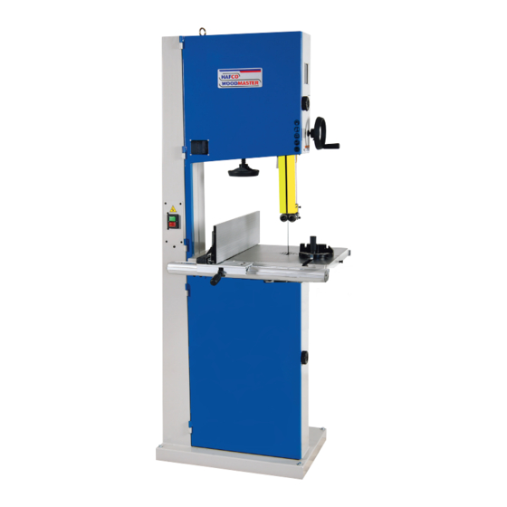
OPERATION MANUAL 1.3 IDENTIFICATION Become familiar with the names and locations of the controls and features shown below to better understand the instructions in this manual. Upper Wheel Cover Top Wheel Adjuster Lifting Point Blade Tension Adjuster Guide Post Hand Wheel Fence Upper Ball Bearing Guide Table Tilt Adjuster... -
Page 6: General Wood Working Machine Safety
OPERATION MANUAL 2.1 GENERAL WOODWORKING MACHINE SAFE PRACTICES DO NOT use this machine unless you have read this manual and have been instructed in the use of this machine in its safe use and operation WARNING This manual provides safety instructions on the proper setup, operation, maintenance, and service of this machine. - Page 7 OPERATION MANUAL 2.1 GENERAL WOODWORKING MACHINE SAFE PRACTICES Make sure the guard that is in position is in good working condition, and guards the machine adequately before operating any equipment or machine. Check and adjust all other safety devices. ...
- Page 8 OPERATION MANUAL 2.1 GENERAL WOODWORKING MACHINE SAFE PRACTICES. Do not try to free a stalled blade before turning the power off. Do not distract or startle an operator while he or she is using woodworking equipment. Horseplay should be prohibited. It can lead to injuries. HAZARDS ASSOCIATED WITH MACHINES INCLUDE, BUT ARE NOT LIMITED TO: •...
-
Page 9: Specific Safety For Drill/Mill
OPERATION MANUAL 2.2 SAFE WORK PROCEDURE FOR BAND SAWS DO NOT use this machine unless you have been instructed in its safe use and operation and have read and understood this manual Safety glasses must Long and loose hair Gloves must not be be worn at all times must be contained. -
Page 10: Power Supply
The electrical circuit must meet the requirements for 240V. NOTE : The use of an extension cord is not recommended as it may decrease the life of electrical components on your machine. ELECTRICAL REQUIREMENTS BP-430A BP-480A Nominal Voltage......240V 240V Cycle..........50 Hz 50Hz Phase.......... -
Page 11: Setup
OPERATION MANUAL 4 SETUP 4.1 UNPACKING This machine was carefully packaged for safe transport. When unpacking, separate all enclosed items from packaging materials and inspect them for shipping damage. If items are damaged, please contact your distributor. NOTE: Save all the packaging materials until you are completely satisfied with the machine and have resolved any issues with the distributor, or the shipping agent. -
Page 12: Anchoring To The Floor
OPERATION MANUAL 4.4 LIFTING INSTRUCTIONS CONT. LIFTING POINT An eye bolt lifting point has been provided on the top of the machine. (Fig.4.1) When lifting the machine only certified lifting slings should be used. Ensure that when lifting, the machine does not tip over. Check that the lifting slings do not interfere with the parts of the machine that may be damaged. -
Page 13: Assembly
OPERATION MANUAL 4.7 ASSEMBLY The machine must be fully assembled before it can be oper- ated. First clean any parts that are coated in rust preventative to ensure the assembly process can proceed smoothly. INSTALLING THE GUIDE POST HAND WHEEL 1. - Page 14 OPERATION MANUAL INSTALLING THE FENCE 1. Attach the back support square tube to the back of the table with the two M6 x 16 socket head cap screws, making sure that the rail is parallel to the table. (Fig. 4.8) 2.
-
Page 15: Tensioning The Blade
OPERATION MANUAL 4.8 TENSIONING THE BLADE. A properly tensioned blade is essential for making accurate cuts and is necessary before making other band saw adjustments. (For blade change instructions see Page 20) To tension the blade: 1. DISCONNECT THE MACHINE FROM THE POWER SUPPLY laDe ension hanD wheel... -
Page 16: Blade Tracking
OPERATION MANUAL 4.9 BLADE TRACKING To operate correctly, the saw blade does needs to run in the centre of the rubber tyre. If the blade rides in the centre of the upper wheel and is centred on the peak of the wheel crown, then the band-saw is tracking correctly and no adjustment is needed. -
Page 17: Test Run
OPERATION MANUAL 4.10 TABLE STOP CALIBRATION After tilting the table the adjustable positive stop allows the table to be reset 90˚ to the blade. To set the positive stop: 1. DISCONNECT BAND SAW FROM POWER! 2. Adjust the blade tension see Page 15 until the blade tension is correct or matches the predetermined settying on the tension scale. -
Page 18: Operation
OPERATION MANUAL 5. OPERATION 5.1 Basic Controls laDe ension Use the descriptions below to become familiar with heel the basic controls of your machine. Blade Tension Hand Wheel: Adjusts the tension on the blade. (Fig. 5.1) Blade Tracking Adjustment Knob: Adjusts the blade tracking. -
Page 19: Blade Information
“Tooth Style. ” As shown Fig.5.7 sku: w433a bP-430a 3340 sku: w433b sku: w433c arrow sku: w434a bP-480a 3630 sku: w434b... -
Page 20: Changing The Blade
OPERATION MANUAL 5.3 CHANGING THE BLADE To remove the blade: 1. DISCONNECT POWER FROM THE BAND SAW 2. Release the blade tension by turning the blade tension hand wheel (Fig. 5.8) or turn the quick release lever to the left.(Fig. 5.9) 4. -
Page 21: Adjusting The Speed
OPERATION MANUAL 5.4 ADJUSTING THE SPEED The band saws listed in this manual are fitted with a pulley system that allows for two speeds to be available for the operation. Below are the details for adjusting the speeds. To change the speed 1. -
Page 22: Adjusting Support Bearings
OPERATION MANUAL 5.6 ADJUSTING SUPPORT BEARINGS The support bearings are positioned behind the blade PPer uiDe for support during cutting operations. Proper adjust- ment of the support bearings is an important part of making accurate cuts. The procedure is as follows. 1. -
Page 23: Maintenance
OPERATION MANUAL 6. MAINTENANCE Review the troubleshooting and procedures in this section to fix or adjust your machine if a problem develops. If you need replacement parts or you are unsure of your repair skills, then contact your local distributor or service provider. NOTE: Hafco/Woodmaster advise that exten- sion leads should not be used permanently, but recommend that the plug be placed directly in to a wall socket. -
Page 24: Wheel Alignment
OPERATION MANUAL Symptom Possible Cause Possible Solution Machine slows 1. Applying too much pressure to workpiece. 1. Feed workpiece slower and in a smooth when operating motion 2. Blade is dull. 2.. Replace blade Ticking sound 1. Blade weld contacting support bearing. 1. -
Page 25: Spare Parts
BP-430A Machine Spare Parts List......... 28 BP-430A Fence Spare Parts Diagram......32 BP-430A Fence Spare Parts List........33 BP-430A Upper Guide Parts Diagram & List....34 BP-430A Lower Guide Parts Diagram & List....35 BP-480A Machine Spare Parts Diagram...... 36 BP-480A Machine Spare Parts List......... -
Page 26: Bp-430A Machine Spare Parts Diagram
OPERATION MANUAL BP-430A MACHINE SPARE PARTS DIAGRAM... - Page 27 OPERATION MANUAL BP-430A MACHINE SPARE PARTS DIAGRAM...
-
Page 28: Bp-430A Machine Spare Parts List
OPERATION MANUAL BP-430A MACHINE SPARE PARTS LIST Part No. Description Specification WF040808 FLAT WASHER M4x8 NH040700 SP040200 PAN HEAD SCREW M4x8 995101 RING 136161 MACHINE BODY NF050800 IC135042 SWITCH CORD WF061310 FLAT WASHER M6x13 IC135001 POWER CORD 3P+G NH061000 135040... - Page 29 OPERATION MANUAL BP-430A MACHINE SPARE PARTS LIST Part No. Description Specification SR089400 HEX SOCKET BOLT M8x16 WF083030 FLAT WASHER M8x30 135016 UPPER WHEEL SLIDING BRACKET SR060500 HEX SOCKET BOLT M6x25 BR000044 RIVET Ø3.2x10 SR060200 HEX SOCKET BOLT M6x10 135004 LIMPID PIECE...
- Page 30 OPERATION MANUAL BP-430A MACHINE SPARE PARTS LIST Part No. Description Specification 135005 LOWER WHEEL SHAFT MH135001 MOTOR 1 HP SR100500 HEX SOCKET BOLT M10x25 WS100000 SPRING WASHER 135064 MOTOR BRACKET SJ080400 HEX SOCKET HEAD SCREW M8x20 135081 PLATE SF050200 PAN HEAD BOLT W/FLANGE...
- Page 31 OPERATION MANUAL BP-430A MACHINE SPARE PARTS LIST Part No. Description Specification 135054 FIBER WASHER 4-13x6x1.2 135037 SLIDING PLATE AB135055 UPPER BLADE GUIDE SUPPORT(ASM) SR060400 HEX SOCKET BOLT M6x20 135006 HANDLE WHEEL SR060400 HEX SOCKET BOLT M6x20 SJ080400 HEX SOCKET BOTOM HEAD SCREW...
-
Page 32: Bp-430A Fence Spare Parts Diagram
OPERATION MANUAL BP-430A FENCE SPARE PARTS DIAGRAM... -
Page 33: Bp-430A Fence Spare Parts List
OPERATION MANUAL BP-430A FENCE SPARE PARTS LIST Part No. Description Specification ACl98082 FENCE (AL) 198008 BRACKET WF061310 FLAT WASHER M6x13 SF049200 PAN HEAD BOLT W/FLANGE M4x8 SH060400 HEX HEAD BOLT M6x20 SR069400 HEX SOCKET BOLT M6x16 wS060000 SPRING WASHER NH061000... -
Page 34: Bp-430A Upper Guide Parts Diagram & List
OPERATION MANUAL BP-430A UPPER GUIDE SPARE PARTS DIAGRAM BP-430A UPPER GUIDE SPARE PARTS LIST Part No. Description Specification 135091 UPPER BLADE GUIDE SUPPORT 13590 BIAS SHAFT RS150000 RING BB620202A BALL BEARING 6202ZZ 136445 HANDLE BUSHING SR060703 HEX SOCKET BOLT M6x35... -
Page 35: Bp-430A Lower Guide Parts Diagram & List
OPERATION MANUAL BP-430A LOWER GUIDE SPARE PARTS DIAGRAM BP-430A LOWER GUIDE SPARE PARTS LIST Part No. Description Specification 135091 UPPER BLADE GUIDE SUPPORT 135090 BIAS SHAFT RS150000 RING BB620202A BALL BEARING 6202ZZ 136445 HANDLE BUSHING SR060703 HEX SOCKET BOLT M6x35... -
Page 36: Bp-480A Machine Spare Parts Diagram
OPERATION MANUAL BP-480A MACHINE SPARE PARTS DIAGRAM... - Page 37 OPERATION MANUAL BP-480A MACHINE SPARE PARTS DIAGRAM...
-
Page 38: Bp-480A Machine Spare Parts List
OPERATION MANUAL BP-480A MACHINE SPARE PARTS LIST Part No. Description Specification WF040808 FLAT WASHER M4x8 NH040700 SP040200 PAN HEAD SCREW M4x8 995101 RING 13612 MACHINE BODY NF050800 IC135042 SWITCH CORD WF061310 FLAT WASHER M6x13 IC135001 POWER CORD 3P+G NH061000 135040 POINTER 135073 STEP SCREW... - Page 39 OPERATION MANUAL BP-480A MACHINE SPARE PARTS LIST Part No. Description Specification 135067 BUSHING SR089400 HEX SOCKET BOLT M8x16 WF083030 FLAT WASHER M8x30 135016 UPPER WHEEL SLIDING BRACKET SR061000 HEX SOCKET BOLT M6x25 BR000041 RIVET Ø3.2x10 SR060200 HEX SOCKET BOLT M6x10 135004 LIMPID PIECE SF040700...
- Page 40 OPERATION MANUAL BP-480A MACHINE SPARE PARTS LIST Part No. Description Specification 135005 LOWER WHEEL SHAFT MH135004 MOTOR 1 HP SR100500 HEX SOCKET BOLT M10x25 WS100000 SPRING WASHER 135064 MOTOR BRACKET SJ080400 HEX SOCKET HEAD SCREW M8x20 135081 PLATE SF050200 PAN HEAD BOLT W/FLANGE M5x10 135065 LOCATE BLOCK...
- Page 41 OPERATION MANUAL BP-480A MACHINE SPARE PARTS LIST Part No. Description Specification 135054 FIBER WASHER 4-13x6x1.2 135037 SLIDING PLATE AB135055 UPPER BLADE GUIDE SUPPORT(ASM) SR060400 HEX SOCKET BOLT M6x20 135006 HANDLE WHEEL SR060400 HEX SOCKET BOLT M6x20 SJ080400 HEX SOCKET BOTOM HEAD SCREW M8x20 WS080000 SPRING WASHER...
-
Page 42: Bp-480A Fence Spare Parts Diagram
OPERATION MANUAL BP-480A FENCE SPARE PARTS DIAGRAM... -
Page 43: Bp-480A Fence Spare Parts List
OPERATION MANUAL BP-480A FENCE SPARE PARTS LIST Part No. Description Specification AC198083 FENCE (AL) 198008 BRACKET WF061310 FLAT WASHER M6x13 SF049200 PAN HEAD BOLT W/FLANGE M4x8 SH060400 HEX HEAD BOLT M6x20 SR069400 HEX SOCKET BOLT M6x16 3S060000 SPRING WASHER NH061000 LM001035 SCALE ST039300... - Page 44 OPERATION MANUAL BP-480A UPPER GUIDE SPARE PARTS DIAGRAM BP-480A UPPER GUIDE SPARE PARTS LIST Part No. Description Specification 135091 UPPER BLADE GUIDE SUPPORT 13590 BIAS SHAFT RS150000 RING BB620202A BALL BEARING 6202ZZ 136445 HANDLE BUSHING SR060703 HEX SOCKET BOLT M6x35 135060 UPPER SPACING SLEEVE SS060200...
-
Page 45: Bp-480A Lower Guide Parts Diagram & List
OPERATION MANUAL BP-480A LOWER GUIDE SPARE PARTS DIAGRAM BP-480A LOWER GUIDE SPARE PARTS LIST Part No. Description Specification 135091 UPPER BLADE GUIDE SUPPORT 135090 BIAS SHAFT RS150000 RING BB620202A BALL BEARING 6202ZZ 136445 HANDLE BUSHING SR060703 HEX SOCKET BOLT M6x35 135060 UPPER SPACING SLEEVE SS060200... -
Page 46: Electrical Drawing
OPERATION MANUAL ELECTRICAL DRAWING... -
Page 47: Risk Assessment Sheets
General Machinery Safety Instructions Machinery House requires you to read this entire Manual before using this machine. 1. Read the entire Manual before starting 14. Use correct amperage extension cords. machinery. Machinery may cause serious injury if Undersized extension cords overheat and lose not correctly used. - Page 48 Wood Bandsaw Safety Instructions Machinery House requires you to read this entire Manual before using this machine. 1. Maintenance. to other persons in the area and know what is Make sure the bandsaw is turned going on around the area to ensure unintended off and disconnect from the main power supply accidents.
Need help?
Do you have a question about the BP-430A and is the answer not in the manual?
Questions and answers