
Related Manuals for Hafco Woodmaster SB-12


Summary of Contents for Hafco Woodmaster SB-12
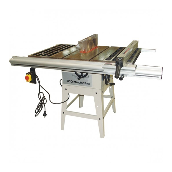
- Page 1 Operator’s Manual TABLE SAW W452 SB-12 5/6/2013 CAUTION: Read and follow all Safety Rules and Operating Instructions before First Use of this Product. 1306-TJZ10/2-TJZ12/2...
-
Page 2: Table Of Contents
TABLE OF CONTENTS Product Specifications ........................2 Safety ............................3 Accessories and Attachments ....................5 Carton Contents .........................5 Assembly ............................7 Operation ...........................10 Maintenance..........................12 Trouble Shooting Chart ......................12 Assembly Diagram……......................13 PRODUCT SPECIFICATIONS TJZ10/2 TJZ12/2 Model Motor 2200W (3HP) 2200W (3HP) Table Size 1030x685 mm 1030x685 mm Φ254 mm Φ305 mm... -
Page 3: Safety
SAFETY GENERAL Before putting into use, fault loop impedance and suitability of over current protective devices need to be approved according to your safety standards. Read through the entire operating instructions before putting into operation. In addition to the safety requirements contained in these operating instructions, you must be careful to observe your country’s applicable regulations. - Page 4 The splitting wedge is an important safety feature. The work piece is fed through the splitting wedge which prevents the cut from closing behind the saw blade and also prevents the work piece from kicking back. Lower the blade guard onto the work piece during every working operation. It must stand horizontally above the saw blade.
-
Page 5: Accessories And Attachments
Even when all safety measures are taken, some remaining hazards which are not yet evident may still be present Electrical Connection The electric motor is connected in a ready to operate state. The mains connection at the customer’s work place and the extension cable used must correspond to these regulations. - Page 6 TABLE OF LOOSE PARTS Unpack carton; check you machine to see parts listed below: Rip fence Back fence support Dado insert Blade guard assembly Motor assembly V-belt Belt guard Miter gauge Wrench 10. Extension table 2pcs 11. Table cabinet assembly 12.
-
Page 7: Assembly
Assembly Important: When unpacking, take care to locate all the small parts of the machine supplied inside the carton box. Assemble stand with M8 hex nuts, 8mm flat washers and M8X16 carriage bolts. Then install the table cabinet assembly to the stand and secure it with M8X16 hex head bolt, 8mm flat washer and M8 hex nut. M8X16 hex bolt M8X16... - Page 8 Assemble the height adjusting hand wheels and angle adjusting hand wheel. Attach the two lock knobs. Lock knob Height adjusting hand wheel Angle adjusting hand wheel Assemble the extension table with M8 hex head bolts and 8mm flat washers. Adjust set screws to make tables flush and level. Then tighten the bolts. Levelling ruler Extension table M8 hex bolt and 8mm...
- Page 9 Back fence support Front fence support Assemble the switch box to the front fence support and fix it with screws and nuts Switch box Place the rip fence upon the fence support. Ensure the fence bottom surface is parallel with the table surface by adjusting the height of the fence support.
-
Page 10: Operation
Remove the table insert. Assemble the blade guard assembly with two M6X10 hex bolts and 6mm flat washers. Align the riving knife with the blade and tighten the bolts. M6X10 hex bolts and 6mm flat washers M6X10 hex bolts and 6mm flat washers After all these steps, the machine’s assembly is finished. - Page 11 Lock knob Height adjusting hand wheel Angle adjusting hand wheel Parallel cuts Adjust the rip fence in accordance with the width of work piece. With both hands (use the push-stick in the region of the saw blade) and push the work piece until it is behind the riving knife.
-
Page 12: Maintenance
Maintenance Warning: Before performing any maintenance, make sure the machine is unplugged from the power supply. Wear goggles when cleaning the machine. Caution: Do not clean synthetic components of the bench using aggressive cleaning agents. We recommend a mild dish washing liquid. The machine must not get into contact with water. Turn on and then off to check the brake stops the blade within 10S every week. -
Page 13: Assembly Diagram
Assembly Diagram Part list for blade guard Reference Description Quantity number Push nut Spring pin Anti-kickback pawl Bushing Riving knife Guard support Spring Blade guard Label M6X10 Hex bolt 6 mm flat washer... - Page 14 Part list for rip fence Reference Reference Description Quantity Description Quantity number number Lock nut Junction plate Rivet Rivet Screw Flitch plate Screw Clamp Left cover Plastic bracket Bracket Ring Right cover Idler wheel Pan head screw Fence Flat washer Support plate Pointer Spring pin...
- Page 15 Part list for stand Reference Description Quantity number Table cabinet assembly Front/rear brace Front/rear top frame Side top frame Side brace M8X16 hex bolt Flat washer Lock washer Hex nut Carriage bolt...
- Page 16 Part list for table Reference Reference Description Quantity Description Quantity number number Screw Hex bolt Fence support cover Flat washer Front fence support Hex nut Scale Back fence support Fence support cover Flat washer Hex bolt Flat washer Pan head screw Washer Rack Switch box cover...
- Page 18 Parts list for blade drive and tilt mechanism Reference Reference Description Quantity Description Quantity number number Cabinet Blade flange Pan head screw Arbor nut Hex nut Flat washer Spring pin Support Spring pin Hex bolt Worm gear Hex bolt Spacer Cord clamp Elevation shaft Hex nut...
Need help?
Do you have a question about the SB-12 and is the answer not in the manual?
Questions and answers