Sign In
Upload
Download
Table of Contents
Contents
Add to my manuals
Delete from my manuals
Share
URL of this page:
HTML Link:
Bookmark this page
Add
Manual will be automatically added to "My Manuals"
Print this page
×
Bookmark added
×
Added to my manuals
Manuals
Brands
Hafco Woodmaster Manuals
Saw
BP-255
Operation manual
Hafco Woodmaster BP-255 Operation Manual
Wood band saw
Hide thumbs
1
2
Table Of Contents
3
4
5
6
7
8
9
10
11
12
13
14
15
16
17
18
19
20
21
22
23
24
25
26
27
28
29
30
31
32
33
34
35
page
of
35
Go
/
35
Contents
Table of Contents
Troubleshooting
Bookmarks
Table of Contents
Table of Contents
1 General Machine Information
Identification
Specifications
2 Important Safety Information
Safety Requirements
Safety for Band Saws
3 Installation
Site Consideration
Electrical Installation
Unpacking
Installation
Test Run
4 Adjustments
Tilting Table
Blade Tracking
Tensioning the Blade
Adjusting Support Bearings
Blade Guide Adjustment
Adjusting the Speed
5 Operation
Basic Controls
Blade Information
Changing the Blade
6 Maintenance
Troubleshooting
Wheel Alignment
Spare Parts
Advertisement
Quick Links
1
Spare Parts
Download this manual
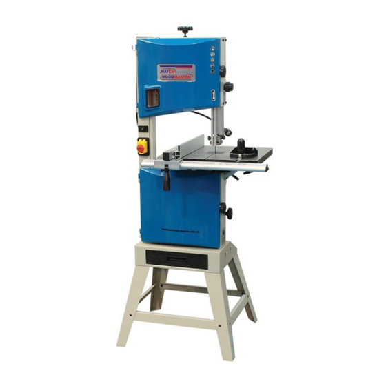
OPERATION MANUAL
WOOD BAND SAW
Models
BP-255, BP-310, BP-360
Order Code W950,
Code W952,
Order Code W955
Edition No
:WBS-003
Date of Issue
: 07/2020
Table of
Contents
Previous
Page
Next
Page
1
2
3
4
5
Advertisement
Table of Contents
Need help?
Do you have a question about the BP-255 and is the answer not in the manual?
Ask a question
Questions and answers
Related Manuals for Hafco Woodmaster BP-255
Saw Hafco Woodmaster BP-430A Operation Manual
Wood band saw (49 pages)
Saw Hafco Woodmaster BP-310 Operation Manual
Wood band saw (35 pages)
Saw Hafco Woodmaster BP-360 Operation Manual
Wood band saw (35 pages)
Saw Hafco Woodmaster BP-480 Instruction Manual
Wood band saw (32 pages)
Saw Hafco Woodmaster W4346 Instruction Manual
Wood band saw (32 pages)
Saw Hafco Woodmaster BP-305 Instruction Manual
(12 pages)
Saw Hafco Woodmaster TAFE-BP-480 Instruction Manual
Qld schools, wood working band saw 415v 465 x 310mm (35 pages)
Saw Hafco Woodmaster TAFE-BP-480 Instruction Manual
Qld schools, wood working band saw 240v 465 x 310mm (35 pages)
Saw Hafco Woodmaster SB-12 Operator's Manual
(18 pages)
Saw Hafco Woodmaster MJ2325D Manual
10" sliding table saws (33 pages)
This manual is also suitable for:
Bp-310
Bp-360
W950
W952
W955
Table of Contents
Print
Rename the bookmark
Delete bookmark?
Delete from my manuals?
Login
Sign In
OR
Sign in with Facebook
Sign in with Google
Upload manual
Upload from disk
Upload from URL


Need help?
Do you have a question about the BP-255 and is the answer not in the manual?
Questions and answers