
Related Manuals for KPS KPS-PA50 MINI


Summary of Contents for KPS KPS-PA50 MINI
- Page 1 MANUAL DE FUNCIONAMIENTO INSTRUCTIONS MANUAL Minipinza amperimétrica Digital clamp meter KPS-PA50 MINI 602150018...
-
Page 2: Información Sobre Seguridad
KPS-PA50 MINI • Minipinza amperimétrica INFORMACIÓN SOBRE SEGURIDAD ADVERTENCIA Tenga en cuenta que una utilización inadecuada puede hacer que se produzcan descargas eléctricas o que el instrumento sufra daños du- rante el uso. Cuando utilice el instrumento, observe las medidas de seguridad habituales y siga todas las medidas de seguridad indicadas en el manual de funcionamiento. - Page 3 KPS-PA50 MINI • Minipinza amperimétrica • No toque las puntas metálicas de las puntas de prueba cuando el instru- mento esté conectado al circuito a medir. • Mantenga los dedos por detrás de los protectores de la sonda al realizar mediciones con una tensión eficaz de más de 60V CC ó 30V rms CA.
- Page 4 KPS-PA50 MINI • Minipinza amperimétrica Categoría de sobretensión (instalación) III, grado de contami- nación 2 según IEC61010-1. Hace referencia al nivel de protec- CAT III ción contra la tensión de rigidez dieléctrica a impulso suminis- trada. Cumple con la directiva de la Unión Europea Terminal de tierra 1.4 Mantenimiento...
- Page 5 KPS-PA50 MINI • Minipinza amperimétrica resistencia, frecuencia, ciclo de trabajo y capacidad, así como pruebas de continuidad y de diodos. • Escala automática y manual disponibles. • El instrumento cuenta con una función de retención de la lectura. • El instrumento cuenta con una función de medición del valor efectivo (en la escala A CA y V CA).
- Page 6 KPS-PA50 MINI • Minipinza amperimétrica (19) Cubierta del compartimento de las pilas 2.2 Selector, botones y conectores de entrada Botón HOLD/B.L • Para retener la lectura o controlar la retroiluminación. Botón SEL • Para cambiar entre las diferentes funciones de medición.
- Page 7 KPS-PA50 MINI • Minipinza amperimétrica • Para cambiar entre las funciones de medición de frecuencia y trabajo. Botón MAX/MIN: • Se utiliza para cambiar entre las funciones de medición de valor máximo/ mínimo. Selector giratorio: • Se utiliza para cambiar entre las funciones de medición de valor máximo/ mínimo. Posición OFF • Para apagar el instrumento.
-
Page 8: Especificaciones
KPS-PA50 MINI • Minipinza amperimétrica AUTO Modo de escala automática MANU Modo de escala manual Valor máximo medido Valor mínimo medido ZERO Cero A CC Apagado automático Batería baja TRMS RMS efectivo Indica que los datos de la pantalla están siendo rete-... - Page 9 KPS-PA50 MINI • Minipinza amperimétrica • Pantalla: pantalla LCD. • Valor máximo en pantalla: 6599 dígitos • Indicación automática de polaridad: ‘-‘ para polaridad negativa • Indicación de fuera de escala: ‘0L’ o ‘-0L’ • Frecuencia de muestreo: 0,4 segundos por muestreo aproximadamente • Indicación de unidades: función y unidad • Tiempo de apagado automático: 30 minutos...
- Page 10 KPS-PA50 MINI • Minipinza amperimétrica Corriente CA Escala Resolución Precisión 0,01A ±3,0% de la lectura ± 10 dígitos 600A 0,1A - Corriente máxima de entrada: 600A - Escala de frecuencia: 40 a 400Hz - Respuesta: valor RMS eficaz. Punta de corriente de arranque Escala Resolución Precisión 0,01A <60A tomar sólo como referencia ±3,0% de la lectura ± 10 dígitos 600A 0,1A - Tiempo de integración: 100ms...
- Page 11 KPS-PA50 MINI • Minipinza amperimétrica Tensión CC Escala Resolución Precisión 660mV 0,1mV 6,6V 0,001V ± (0,8% de la lectura + 3 dígitos) 0,01V 600V 0,1V ± (1,0% de la lectura + 5 dígitos) - Impedancia de entrada: 10MW - Protección contra sobrecarga: Escala 660mV: 250V CC o CA RMS, Escalas 6,6V-600V: 600V CC o 600V CA RMS.
- Page 12 KPS-PA50 MINI • Minipinza amperimétrica Nota: En escalas de tensión pequeñas, aparecerán lecturas inestables antes de que las puntas de prueba estén en contacto con el circuito. Esto es normal debido a la alta sensibilidad del instrumento. La lectura correcta se mostrará una vez que las puntas estén en contacto con el circuito. Frecuencia • Escala A (pinza de corriente): Escala Resolución...
- Page 13 KPS-PA50 MINI • Minipinza amperimétrica Ciclo de trabajo • Escala A (pinza de corriente): Escala Resolución Precisión 10 - 95% 0,1% ± 3,0% - Respuesta de frecuencia: 10 ~1kHz - Escala de tensión de entrada: ≥1A CA RMS (mayor corriente de entrada a una mayor frecuencia) - Corriente máxima de entrada: 600A • Escala V: - Respuesta de frecuencia: 10 ~ 10 kHz - Escala de tensión de entrada: ≥ 0,2V CA RMS (mayor tensión de entrada a...
- Page 14 KPS-PA50 MINI • Minipinza amperimétrica Diodos Escala Resolución Descripción Se muestra la tensión directa aproximada del 0,001V diodo - Corriente CC directa ~ 1mA Continuidad Escala Resolución Descripción El avisador integrado emitirá un sonido si la 0,1W resistencia es inferior a 30W.
-
Page 15: Instrucciones De Funcionamiento
KPS-PA50 MINI • Minipinza amperimétrica INSTRUCCIONES DE FUNCIONAMIENTO 4.1 Retención de las lecturas • Pulse el botón “HOLD/B.L” para retener las lecturas durante la medición.Se retendrá el valor que aparece en pantalla. • Pulse de nuevo el botón “HOLD/B.L” para liberar la función de retención de la lectura. - Page 16 KPS-PA50 MINI • Minipinza amperimétrica 4.4 Selección de la medición del valor máximo/mínimo • En todas las escalas, pulse una vez el botón “MAX/MIN” y el instrumento entrará en el modo de medición del valor máximo. Pulse el botón dos veces y el instrumento entrará...
- Page 17 KPS-PA50 MINI • Minipinza amperimétrica madamente 30 segundos. • En este periodo de tiempo, si pulsa la tecla “B.L/HOLD” durante más de dos segundos la retroiluminación se apagará. • En la escala de corriente, al activar la retroiluminación la iluminación del maxilar de la pinza se desactivará...
- Page 18 KPS-PA50 MINI • Minipinza amperimétrica • Coloque el selector para elegir la función y la escala adecuadas para la medición. En el modo manual, seleccione la escala más alta cuando no se conozca la escala del valor a medir. • Al realizar la conexión, conecte en primer lugar la punta de prueba común y a continuación las puntas de prueba con carga.
- Page 19 KPS-PA50 MINI • Minipinza amperimétrica Correcto Incorrecto 4.11 Medición de tensión ADVERTENCIA Peligro de electrocución. Preste especial atención para evitar descar- gas eléctricas durante la medición de altas tensiones. No conecte tensiones superiores a 750V CA rms. • Introduzca el cable de prueba negro en el conector COM y el cable de prue- ba rojo en el conector de ENTRADA.
- Page 20 KPS-PA50 MINI • Digital clamp meter • En el modo de medición relativo no se puede utilizar la escala de medición automática. • “ ”significa que la tensión máxima de entrada es de 750V CA o 1000V. • Si la lectura registrada por el instrumento es mayor de 750V CA rms, béste emitirá...
- Page 21 KPS-PA50 MINI • Digital clamp meter INPUT. Elija la escala de medición adecuada. 2) Coloque el selector en la posición de tensión CA V o mV. Pulse la tecla FUNC para acceder al modo de medición de tensión CA. 3) Pulse la tecla “Hz/%” para seleccionar el modo de medición de frecuencia. 4) Conecte la pica a la señal o a ambos extremos de la carga en paralelo para efectuar la medición.
- Page 22 KPS-PA50 MINI • Digital clamp meter 4.13 Medición de la resistencia ADVERTENCIA Riesgo de descarga eléctrica. Al realizar la medición de la impedancia de un circuito, asegúrese de que la alimentación esté desconectada y que los condensadores del circuito estén completamente descar- gados.
- Page 23 KPS-PA50 MINI • Digital clamp meter ADVERTENCIA Riesgo de descarga eléctrica. Al realizar la medición de la impedancia de un circuito, asegúrese de que la alimentación esté desconectada y que los condensadores del circuito estén completamente descar- gados. • Introduzca el cable de prueba negro en el conector COM y el cable de prue- ba rojo en el conector de ENTRADA.
-
Page 24: Mantenimiento
KPS-PA50 MINI • Digital clamp meter 4.16 Medición de la capacidad ADVERTENCIA Peligro de electrocución. Asegúrese de que la alimentación del circui- to esté desconectada y que los condensadores estén completamente descargados antes de medir la capacitancia de un condensador. - Page 25 KPS-PA50 MINI • Digital clamp meter 5.2 Sustitución de las puntas de prueba ADVERTENCIA Las puntas de repuesto deben estar en buen estado y sus especifica- ciones deben ser iguales o equivalentes: 1000V 10A. Se deben sustituir las puntas de prueba si el revestimiento aislante está daña- do, por ejemplo el cable interior está al descubierto.
-
Page 26: Safety Information
KPS-PA50 MINI • Digital clamp meter SAFETY INFORMATION WARNING BE EXTREMELY CAREFUL WHEN USING THIS METER. Improper use of this device can result in electric shock or destruction of the meter. Take all normal safety precautions and follow the safeguards suggest- ed in this manual. - Page 27 KPS-PA50 MINI • Digital clamp meter • Keep your fingers behind the probe barriers when taking a measurement with an effective voltage above 60V DC or 30V rms AC. • Do not take voltage measurement if the value between the terminals and earth ground exceeds 600V.
- Page 28 KPS-PA50 MINI • Digital clamp meter Earth (ground) terminal 1.4 Maintenance • Do not attempt to remove the rear case to adjust or repair the meter. Such actions should only be performed by a technician who fully understands the meter and the danger involved. • Before opening the case and battery cover of the meter, always disconnect test leads from all sources of electric current.
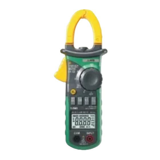
- Page 29 KPS-PA50 MINI • Digital clamp meter (2) Clamp Lighting Bulb (3) Panel (4) Trigger (5) Function Switch Button (SEL) (6) MAX/MIN Switch Button (MAX/MIN) (7) Auto/Manual Switch Button (RAN) (8) Liquid Crystal Display (LCD) (9) COM Jack (10) Input Jack (11) Hz/Duty Switch Button (Hz/%) (12) Reading Hold/Back Light Button (HOLD/B.L) (13) Rotary selector (14) OFF - power switch (15) “+”...
- Page 30 KPS-PA50 MINI • Digital clamp meter 2.2 Switch, buttons and input jacks HOLD/B.L Button • For holding the reading or control backlight SEL Button • For switching among measuring functions RAN Button • For switching between auto and manual ranges. Hz/% Button • For switching between frequency and duty measuring functions.
- Page 31 KPS-PA50 MINI • Digital clamp meter MAX/MIN Button • For switching between maximum and minimum value measuring function. Rotary Selector • For selecting functions and ranges. OFF Position • For turning off the power. INPUT Jack • For measuring voltage, resistance, frequency, duty, capacitance, diode, and continuity. COM Jack • Common input connection for current, voltage, resistance, frequency, duty, capacitance, diode, continuity measurement. Clamp • For measuring current. 2.3 LCD (Liquid-crystal display) Alternating current...
-
Page 32: Specifications
KPS-PA50 MINI • Digital clamp meter The maximum value is being measured The minimum value is being measured. ZERO DCA zero Auto power off Battery low TRMS True RMS This indicates that the display data is being held. INRUSH Inrush current is being measured. - Page 33 KPS-PA50 MINI • Digital clamp meter • Unit indication: function and unit. • Auto power off time: 30 min. • Operating power : 1.5V×3 AAA batteries • Battery low indication: ‘ ’ on LCD • Temperature factor: < 0.1×Accuracy / ºC • Operating temperature: 0ºC to 40ºC (32ºF to 104ºF). • Storage temperature: -10ºC to 50ºC (10ºF to 122ºF). • Dimensions: 208×78×35mm • Weight: approximate 340g (including batteries) 3.2 Electrical specifications...
- Page 34 KPS-PA50 MINI • Digital clamp meter - Response: true root mean square value INRUSH Current Range Resolution Accuracy 0,01A <60A take it only as referance ± (10.0% of rdg + 60 digits) 600A 0,1A - Integration Time: 100ms - Measurement range: 30 ~ 600A - Max. input current: 600A - Frequency range: 40 to 400Hz - Response: true root mean square value DC Current Range Resolution Accuracy 0,01A ±(3,0% of reading+ 10 digits)
- Page 35 KPS-PA50 MINI • Digital clamp meter contact the circuit. This is normal because the meter is highly sensitive. When the test leads contact the circuit, the true reading will be shown. AC Voltage Range Resolution Accuracy 660mV 0,1mV (1,5% of reading + 10 digits) 6,6V...
- Page 36 KPS-PA50 MINI • Digital clamp meter Escala Resolución Precisión 660Hz 0,1kHz 6,6kHz 0,001kHz ±(1,5% of reading + 5 digits) 10kHz 0,01kHz >10kHz 0,01kHz Take it only as referance - Measurement range: 10 ~ 10kHz - Input voltage range: ≥ 0.2V rms AC (higher input voltage at higher frequency) - Input impedance: 10MΩ - Max. input voltage: 600V rms AC Duty Cycle...
- Page 37 KPS-PA50 MINI • Digital clamp meter Resistance Range Resolution Accuracy 660W 0,1W 6,6kW 0,001kW 66kW 0,01kW ±(1,2% of reading + 2 digits) 660kW 0,1kW 6,6MW 0,001MkW 66MW 0,01MW ± (2,0% of reading + 5 digits) - Open circuit voltage: 0.4V - Overload protection: 250V DC or rms AC Diode Range Resolution...
- Page 38 KPS-PA50 MINI • Digital clamp meter Capacitance Range Resolution Accuracy 6,6mF 0,001mF 66mF 0,01mF Lecture <2mF ± (4,0% of reading + 5 digits) 660mF 0,1mF ± (4,0% of reading + 3 digits) 6,6mF 0,001mF 66mF 0,001mF - Overload protection: 250V DC or rms AC OPERATION INSTRUCTIONS 4.1 Holding readings • Press the “HOLD/B.L” button to hold the readings while taking measurement and the value on the display will be held.
-
Page 39: Switching Functions
KPS-PA50 MINI • Digital clamp meter • Press the “Hz/%” button again, meter will be back to the condition of the voltage or current measuring. NOTE: During working at maximum or minimum value measuring function, the meter can’t be changed into frequency or duty cycle measuring mode. 4.4 Switching maximum or minimum value • At all ranges, press the “MAX/MIN”... - Page 40 KPS-PA50 MINI • Digital clamp meter 4.6 Backlight and clamp lighting bulb • Press the ”HOLD/B.L” button for two or more seconds to switch on the back light if the light in the environment is too dim for taking reading, which will last for 30 seconds.
- Page 41 KPS-PA50 MINI • Digital clamp meter the specified value in order to protect the internal circuit from damage. • Turn the rotary selector to the required function and range to be measured. Under the manual mode, choose the highest range when the value scale to be measured is unknown. • Connect the common test lead first and then the charged test leads when making connection. Take away the charged test lead first when disconnect- ing. 4.9 Measuring AC current WARNING Beware of Electrocution. Ensure that the test leads are disconnected from the meter before making current clamp measurements.
- Page 42 KPS-PA50 MINI • Digital clamp meter Correcto Incorrecto 4.10 Measuring DC Current WARNING Beware of Electrocution.Ensure that the test leads are disconnected from the meter before making current clamp measurements. • Set the rotary selector to the A range position.
- Page 43 KPS-PA50 MINI • Digital clamp meter • For optimum results, center the conductor in the jaw. • At the manual range mode, when only ‘OL’ or ‘-OL’ is shown on the LCD, it means the measurement has exceeded the range. A higher range should be selected. • “...
- Page 44 KPS-PA50 MINI • Digital clamp meter Note: (1) Frequency test range is 10Hz -10kHz. ‘00.0’ will be displayed on LCD if the test frequency is lower than 10.0 Hz. It is possible to test the frequency which is higher than 10kHz but the tolerance of the test result can not be ensure. ” means the maximum input voltage is 600V rms AC. (2) “ Measuring duty: WARNING Beware of Electrocution. Ensure that the test leads are disconnected from the meter before making current clamp measurements.
- Page 45 KPS-PA50 MINI • Digital clamp meter 2) For measuring resistance above 1MΩ, it may take a few seconds to get a steady reading. This is normal for high resistance reading. 4.14 Testing diode • Plug the black test lead into the COM jack and the red test lead into the INPUT jack. • Set the rotary selector to the range position.
-
Page 46: Maintenance
KPS-PA50 MINI • Digital clamp meter 4.16 Measuring capacitance WARNING Beware of Electrocution. To avoid electric shock, make sure that the capacitors have been fully discharged before measuring the capaci- tance of a capacitor. • Plug the black test lead into the COM jack and the red test lead into the INPUT jack. - Page 47 KPS-PA50 MINI • Digital clamp meter wire inside is exposed. 6. ACCESSORIES 1) Test Leads: Electric Ratings 1000V 10A 1 pair (set) 2) Operating Manual 1 copy 3) 1.5V AAA Battery 3 piece...
- Page 48 Pol. Industrial de Asipo Calle B, Parcela 41, nave 3 C.P.: E-33428 Llanera Asturias, España (Spain) Tel.: +34 985 081 870 Fax: +34 985 081 875 info@kps-soluciones.es www.kps-soluciones.es...
Need help?
Do you have a question about the KPS-PA50 MINI and is the answer not in the manual?
Questions and answers