Table of Contents
Advertisement
Quick Links
SERVICE MANUAL
For your convenience, all service parts, identified in this manual are available through Eiki's normal distribution chan-
nels.
In addition to service part number, the generic descriptions have been given, where possible, to allow your service
technicians to substitute equivalent components which might be available from other sources.
All orders for service parts will be honored. However, in instances where generic components are considered to be
available from several common sources, as would be the case with an industry standard fuse, resistor, or semicon-
ductor, it may be more economical and expeditious to purchase the part locally.
Product code
Lc-XBM31
1 122 523 41
(KT8BE)
1 122 524 41
(LT8BE)
1 122 524 46
(LT8GE)
Multimedia Projector
ForeWord
FILE NO.
Model No.
original Version
Chassis No. KT8-XBM3100
Give complete " Chassis No. " for parts
order or servicing, it is shown on the rat-
ing sheet on the cabinet on the projector.
REFERENCE NO.
Lc-XBM31
U.S.A, Canada,
Europe, Hong Kong
SM
5111295-00
Advertisement
Table of Contents

Related Manuals for Eiki LC-XBM31


Summary of Contents for Eiki LC-XBM31
-
Page 1: Service Manual
ForeWord For your convenience, all service parts, identified in this manual are available through Eiki’s normal distribution chan- nels. In addition to service part number, the generic descriptions have been given, where possible, to allow your service technicians to substitute equivalent components which might be available from other sources. -
Page 2: Table Of Contents
Contents SERVICE MANUAL ............1 Parts Location Diagrams ..........70 Contents ................ 2 Mechanical Parts List ..........77 Safety Instructions ............3 Electrical Parts List ............78 Safety Precautions ............. 3 Product Safety Notice ..........3 Diagrams & Drawings ..........A1 Service Personnel Warning ........ -
Page 3: Safety Instructions
Safety Instructions Safety Precautions WARNING: The chassis of this projector is isolated (COLD) from AC line by using the converter transformer. Primary side of the converter and lamp power supply unit circuit is connected to the AC line and it is hot, which hot circuit is identified with the line ( ) in the schematic diagram. -
Page 4: Specifications
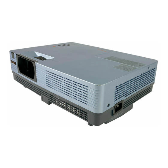
Specifications Mechanical Information Projector Type Multi-media Projector Dimensions (W x H x D) 13.13" x 3.98" x 9.72" 333.5mm x 101.0mm x 247 .0mm) (Not including protrusions) Net Weight 6.4 lbs (2.9 kg) Foot Adjustment 0˚ to 10˚ Panel resolution LCD Panel System 0.63"... -
Page 5: Circuit Protections
Circuit Protections This projector provides the following circuit protections to operate in safety. If the abnormality occurs inside the pro- jector, it will automatically turn off by operating one of the following protection circuits. Thermal switch There is the thermal switch (SW601) inside of the projector to de- tect the internal temperature rising abnormally. -
Page 6: Warning Temperature And Power Failure Protection
Circuit Protections Warning temperature and power failure protection The projector will be automatically turned off when the internal temperature of the projector is abnormally high, or the cooling fans stop spinning, or the power supplies in the projector are failed. - If the WARNING indicator is flashing, it may detect the abnormal temperature inside the projector. -
Page 7: Maintenance
Maintenance replacing the Filters Filter prevents dust from accumulating on the optical elements inside the projector. Should the Filter become clogged with dust particles, it will reduce cooling fans’ effectiveness and may result in internal heat buildup and adversely affect the life of the projector. If a “Filter warning” icon appears on the screen, replace the Filter immediately. - Page 8 Maintenance Attaching the Lens cap When moving this projector or while not using it over an extended period of time, replace the lens cap. Attach the lens cap according to the following procedures. Thread the string through the hole on the lens cap and then tie a knot in the string to secure it in place.
-
Page 9: Lamp Replacement
Lamp Replacement Lamp replacement WArNING: order rePLAceMeNt LAMP - For continued safety, replace with a lamp assembly of the same type No. PoA-LMP142 type. Service Parts No. 610 349 7518 - Allow the projector to cool for at least 45 minutes before you open the lamp cover. -
Page 10: Resetting The Lamp Counter
Lamp Replacement Resetting the Lamp Counter Lamp counter reset Be sure to reset the Lamp replacement counter after the lamp is replaced. Press the Point buttons to choose the Lamp counter function and then press the Point SELECT button to 8 or the access the submenu items. -
Page 11: Security Function Notice
Security Function Notice This projector provides security functions such as "Key lock", "PIN code lock" and "Logo PIN code lock". When the pro- jector has set these security function on, you are required to enter correct PIN code to use the projector. If you do not know the correct PIN code to the projector, the projector can no longer be operated or started. -
Page 12: Standby Mode Notice
Standby Mode Notice This projector provides 2 types of standby mode, Eco standby and Network standby. According to the standby mode "Eco" or "Network", several functions are restricted as shown in the table below. To change the standby mode, use the projector's menu "Setting". -
Page 13: Mechanical Disassembly
Mechanical Disassembly Mechanical disassembly should be made following procedures in numerical or- Screws Expression der. (Type ) mm Diameter x Length Following steps show the basic procedures, therefore unnecessary step may T type M Type be ignored. Caution: The parts and screws should be placed exactly the same position as the original otherwise it may cause loss of performance and product safety. - Page 14 Mechanical Disassembly x Main Board, AV Panel, Audio Jack, Audio AMP and Speaker (SP901) removal 1. Remove 4 screws A (M3x8) and 2 screws B(M4x6) to remove the Lamp back shield and the Right shield. 2. Remove 2 screws C (T3x8) and 1 screw D(M4x6) to remove the Main Board. 3.
- Page 15 Mechanical Disassembly c optical unit, Lamp Ass'y, SW902 and Iris Ass'y removal 1. Remove the Lens spacer sheet-top. 2. Loose 3 screws A(M3x7) to remove the Lamp Ass'y. Remove 5 screws B(T3x8) to remove the Optical Unit, Remove 4 screws C(T3x8) and 1 screw D(T3x8) to remove the Lamp holder and Ballast socket.
- Page 16 Mechanical Disassembly v Mounting duct and fans(FN001, FN003, FN004, FN005) removal 1. Remove 3 screws A(T3x8) and 2 screws B(T3x12) to remove the fan(FN001), fan duct top and bottom. 2. Remove 5 screws C(T3x8) and unhook 3 hooks to remove the duct top. 3.
- Page 17 Mechanical Disassembly b Power board, Fan(FN002) and Filter Ass'y removal 1. Remove the Power board spacer sheet. 2. Remove 8 screws A(M3x8) and 2 screws B(M4x6) to remove the Power box. 3. Remove the Filter Ass'y. A (M3x8)x8 Power board spacer sheet Power box B(M4x6)x2...
-
Page 18: Optical Parts Disassembly
Optical Parts Disassembly Before taking this procedure, remove Cabinet Top and Main Board following to the “Mechanical Disassembly” . Disassembly requires a 2.0mm hex wrench and a screwdriver. z Projection lens disassembly Note: The optical unit should be removed from the cabinet bottom before re- moving the projection lens. - Page 19 Optical Parts Disassembly c Integrator lens-in disassembly Integrator Lens-In Ass'y PBS marker * Rugged surface Integrator lens-in * Rugged surface facing to PBS Prism Beam Splitter (PBS) Integrator lens-out Integrator lens-in Shield Fig.3 v condenser Lens Ass'y disassembly (M2.5x6)x2 Optical unit top Condenser Lens (G) Ass'y Polarized glass (B) Ass'y *Polarized glass is not re-...
- Page 20 Optical Parts Disassembly b relay out lens disassembly M(2.5x6) Relay lens Ass'y Fig.5 Relay Out lens -20-...
- Page 21 Optical Parts Disassembly n Lcd Panel/Prism Ass’y removal (M3x10)x2 LCD Panel/ Prism Ass’y Fig.6-1 IMPortANt NotIce on Lcd Panel/Prism Ass'y replacement LCD panels used for this model can not be replaced separately. Do not disassemble the LCD Panel/Prism Ass’y. These LCD panels are installed with precision at the factory. When replacing the LCD panel, should be replaced whole of the LCD panels and prism ass’y at once.
- Page 22 Optical Parts Disassembly Panel type check There are 2 types of LCD Panel/Prism Ass'y for this model. Either L-Type or R-Type LCD Panel/Prism Ass'y is used on the projector. Check which type of LCD Panel/Prism Ass'y is used with the figure below. When replacing the LCD Panel/Prism Ass'y, you need to take "Panel Type Check and Setting"...
- Page 23 Optical Parts Disassembly m Locations and directions Parts Name When mounting or assembling the optical parts in the op- Dichroic mirror (B) tical unit, the parts must be mounted in the specified loca- tion and direction as shown in figure below. Dichroic mirror (G) Relay lens (IN) Mirror (R)
-
Page 24: Adjustments
Adjustments Adjustments after Parts Replacement : Adjustment necessary : Check necessary ● ❍ disassembly / replaced Parts condensor Glass Lcd/ condenser relay Power Board Main Board Prism Ass’y Lens (out) Lens (out) Contrast Adjustment G-Contrast adjustment ❍ ● B-Contrast adjustment ❍... -
Page 25: Optical Adjustments
Optical Adjustments Before taking optical adjustments below, remove the Cabinet Top following to the “Mechanical Disassembly” . Remove the Main board and remove the AV panel. (Refer to Fig. 1) Adjustments require a 2.0mm hex wrench and a slot screwdriver. When you adjust condenser lens (OUT) or Relay lens (OUT) adjustment, you need to disconnect FPC cables of LCD panels on the main board. -
Page 26: Contrast Adjustment
Optical Adjustments Contrast adjustment [Before Adjustment] - Input a 100% of black raster signal. A (Fig.2) Loosen a screw on the polarized glass mounting base which you intend to adjust. Adjust the slot to obtain the darkest brightness on the screen by using a slot screwdriver. -
Page 27: Condenser Out Lens Adjustment
Optical Adjustments Condenser Out lens adjustment Turn the projector on by a state of without FPC cables. Project all of lights on the screen. Adjust the adjustment base of condenser out lens assy to make color uniformity in white. 1) If the shading appears on the left or right of the screen as shown White Fig.3-1 , loosen 1 screw... -
Page 28: Relay Lens Out Adjustment
Optical Adjustments Relay lens Out adjustment Turn the projector on by a state of without FPC cables. Project all of lights on the screen. Adjust the adjustment base of relay lens assy to make color unifor- mity in white. If the shading appears on the left or right of the screen as shown in White Fig.4 , loosen 1 screw... -
Page 29: Electrical Adjustments
Electrical Adjustments Service Adjustment Menu Operation to enter the service mode MeNu button SeLect button To enter the “Service Mode” , press and hold the on the projector for more MeNu button than 3 seconds or press and hold the on the remote control for more than 20 seconds. -
Page 30: Circuit Adjustments
Electrical Adjustments Circuit Adjustments CAUTION: The each circuit has been made by the fine adjustment at factory. Do not attempt to adjust the following adjustments except requiring the readjustments in servicing otherwise it may cause loss of performance and product safety. Before adjustment, please turn on the projector more than ten minutes. WArNING : uSe uV rAdIAtIoN eYe ANd SKIN ProtectIoN durING SerVIcING. - Page 31 Electrical Adjustments 1. Panel type check and Setting 3. Auto calibration adjustment [Pc] * Before setting, you need to check which type of LCD 1. Enter the service mode. panel is placed on the projector according to the item 2. Receive the 16-step grey scale computer signal with "LCD Panel/Prism Ass'y removal"...
- Page 32 Electrical Adjustments Gain adjustment [Pc] 4. Auto calibration adjustment [component] 1. Enter the service mode. 2. Receive the 16-step grey scale computer signal with 1. Enter the service mode. computer1 [rGB] mode. 2. Receive the 8 color 100% color bar 480i-component tP35G 3.
- Page 33 Electrical Adjustments 5. Auto calibration adjustment [Video] 7. 50% White adjustment [Pc] 1. Enter the service mode. Equipment Luminance meter 2. Receive the 16-step grey scale composite video sig- Input mode Computer 1 (RGB) Video nal with mode. Input signal 100%-white and 50%-gray computer 3.
- Page 34 Electrical Adjustments 9. Keystone offset adjustment After replacing the G-sensor circuit (IC3850) or Memory IC (IC1371), readjust the Keystone Offset adjustment as follows. 1. Put the projector on a horizontal place with the adjustable feet being minimum range and then enter the service mode.
-
Page 35: Test Points And Locations
Electrical Adjustments Test Points and Locations MAIN BoArd -35-... -
Page 36: Service Adjustment Data Table
Electrical Adjustments Service Adjustment Data Table These initial values are the reference data written from the CPU ROM to memory IC when replaced new memory IC. The adjustment items indicated with “ ✻” are required to readjust following to the “ Electrical adjustments” . Other items should be used with the initial data value. - Page 37 Electrical Adjustments Group/ Item Name Function Initial range Note Item 150 PreCoast YCbCr 480i 0 - 63 151 PostCoast YCbCr 480i 0 - 63 152 PreCoast YCbCr 575i 0 - 63 153 PostCoast YCbCr 575i 0 - 63 154 PreCoast YCbCr 480p 0 - 63 155 PostCoast YCbCr 480p 0 - 63...
- Page 38 Electrical Adjustments Group/ Item Name Function Initial range Note Item Motion Adaptive Weight <KDEINT> 0 - 255 Value 0 : Conservative <====> 4 : 1 Angle Interpolation Level 0 - 4 Aggressive 2 CUE Low Pass Filter Enable <CUELPFEN> 0 - 1 Group deinterlacer setting Effective only for Progressive ON-L2 mode.
- Page 39 Electrical Adjustments Group/ Item Name Function Initial range Note Item Film Detection Sensitivity 0 Global Motion Sensitivity 1 - 5 <FILMSTVT23> Film Detection Sensitivity 1 Video Motion Sensitivity 1 - 5 <VOFSTVT> 2 Video Motion Threshold Low <VOFTHRDA> 0 - 32767 Video Motion Threshold <VOFTHRDB>...
- Page 40 Electrical Adjustments Group/ Item Name Function Initial range Note Item 26 REF_GateDur 0-1023 27 R-BasePos 0-15 28 G-BasePos 0-15 29 B-BasePos 0-15 30 RGB-Adjust Operation STEP=256[0<->256<->51 31 RGB-AdjLv 0-4095 2<->768<->1023] 32 LineR0 0-1023 (MIN<-->MAX Cyclic Operation) 33 LineR1 0-1023 (MIN<-->MAX Cyclic Operation) 34 LineR2 0-1023 (MIN<-->MAX Cyclic Operation)
- Page 41 Electrical Adjustments Group/ Item Name Function Initial range Note Item 94 FrontCTalkR-Cent 2045 0-2047 95 FrontCTalkR-Start 0-255 96 FrontCTalkR-End 0-255 97 FrontCTalkG-Cent 2045 0-2047 98 FrontCTalkG-Start 0-255 99 FrontCTalkG-End 0-255 100 FrontCTalkB-Cent 2045 0-2047 101 FrontCTalkB-Start 0-255 102 FrontCTalkB-End 0-255 103 R-DCOffset-NGain 0-1023 Scan Direction (Front/Rear)
- Page 42 Electrical Adjustments Group/ Item Name Function Initial range Note Item 163 G-DCOffset-P8 0-2047 Scan Direction (Front/Rear) 164 G-DCOffset-P9 0-2047 Scan Direction (Front/Rear) 165 G-DCOffset-P10 0-2047 Scan Direction (Front/Rear) 166 G-DCOffset-P11 0-2047 Scan Direction (Front/Rear) 167 G-DCOffset-P12 0-2047 Scan Direction (Front/Rear) 168 B-DCOffset-PGain 0-1023 Scan Direction (Front/Rear)
- Page 43 Electrical Adjustments Group/ Item Name Function Initial range Note Item 232 CROSSTALK_COEF_R 0-1023 1023 233 CROSSTALK COEF_G 0-1023 1023 234 CROSSTALK COEF_B 0-1023 1023 235 LCCON_ENABLE 236 ENBY_L1 0-255 237 ENBY_H1 0-1023 238 ENBY_L2 0-255 239 ENBY_H2 0-1023 Group Panel Service(6200) 0 R_LCCOM 0-255 1 G_LCCOM...
- Page 44 Electrical Adjustments Group/ Item Name Function Initial range Note Item 0 Logo Prohibition Logo Prohibition (0: Menu, 1: Forced) 0 - 1 Effective after AC On 0: 19200bps, 1: 9600bps, 1 RS232C Baudrate Baud Rate 0 - 2 2: 115200bps 2 PJLink Enable PJLink 0 - 1...
- Page 45 Electrical Adjustments Group/ Item Name Function Initial range Note Item 0 Enable 0=Enable, 1=Disable 0 - 1 1 Modulation frequency 1 - 500 2 Diffusivity 0 - 300 Group Lamp control Luminance Level 1 Data for Dimmer: 0 DIMMER_CTRL_LEVEL1 0-255 Dim Level 1 at the less than the Value Luminance Level 1 Data for Dimmer: 1 DIMMER_CTRL_LEVEL2...
- Page 46 Electrical Adjustments Group/ Item Name Function Initial range Note Item 5 APL Threshold Min 0-255 (AV/PC) 6 APL Threshold Max 0-255 (AV/PC) 10 Close Limit Dimmer 0 0-1023 11 Close Limit Dimmer 1 0-1023 12 Close Limit Dimmer 2 0-1023 13 Close Limit Dimmer 3 0-1023 14 Close Limit Dimmer 4...
- Page 47 Electrical Adjustments Group/ Item Name Function Initial range Note Item Temp A Warning Offset 0-100 (Temp) 16 Temp B Warning Offset Offset of Temp Error (Temp.) 0-100 (Temp) Error Setting Value is increased XC at 17 Temp C Warning Offset the below condition 0-100 (Temp)
- Page 48 Electrical Adjustments Group/ Item Name Function Initial range Note Item 4 Fan 3 Speed Gain 0-255 Group Fan dimmer Setting Dimmer Average measurement Time 0 Dimmer Average Chech (0:10sec. 1:30sec. 2:60 sec. 90: 0-10 Period sec...10:30sec.) 1 Dimmer Average Dimmer Average Value (Read only) 2 Last Voltage Difference 3 Voltage Difference Goal Group...
- Page 49 Electrical Adjustments Group/ Item Name Function Initial range Note Item 11 CR - GAIN AREA V START 0 - 1000 12 Image AREA H WIDTH YCBCR Level Acquiring Area 0 - 4095 13 Image AREA V HIGHT YCBCR Level Acquiring Area Height 0 - 4095 14 Y - OFFSET TARTGET 1 - 255...
- Page 50 Electrical Adjustments Group/ Item Name Function Initial range Note Item 1 Disp Dots 0 �� 4095 2 H Back Porch 0 �� 4095 3 V Back Porch 0 �� 4095 4 Disp Line 0 �� 4095 Group Ycbcr (480i) 0 Total Dots 0 ��...
- Page 51 Electrical Adjustments Group/ Item Name Function Initial range Note Item 1 Disp Dots 1872 0 �� 4095 2 H Back Porch 0 �� 4095 3 V Back Porch 0 �� 4095 4 Disp Line 1012 0 �� 4095 Group rGB Video (480i) 0 Total Dots 0 ��...
- Page 52 Electrical Adjustments Group/ Item Name Function Initial range Note Item 1 Disp Dots 1872 0 �� 4095 2 H Back Porch 0 �� 4095 3 V Back Porch 0 �� 4095 4 Disp Line 1008 0 �� 4095 Group color Shading Adj offset 0 R-Max 0 - 255 1 R-Mid1...
-
Page 53: Chassis Block Diagrams
Chassis Block Diagrams chassis over view FN001 FN002 FN003 FN004 FN005 -53-... -
Page 54: System Control
Chassis Block Diagrams System control IC301 SCALER <PW190> -54-... -
Page 55: Lamp Control
Chassis Block Diagrams Lamp control -55-... -
Page 56: Audio Circuit
Chassis Block Diagrams Audio circuit -56-... -
Page 57: Power Supply & Protection Circuit
Chassis Block Diagrams Power supply & protection circuit -57-... -
Page 58: Fan Control Circuit
Chassis Block Diagrams Fan control circuit TPFANA Q7812 FN003 S16V FAN_A D3623 D3613 Q7801 FN004 IC7811 D3622 Q7813 Q7864 FN005 D3621 TPFANB Q7862 FN001 FAN_B D3628 TPFANC D3614 FN002 IC7841 FAN_C Regulator Q7842 D3626 D3644 Q7802 Q3601 P_FAIL P_FAIL P_Fail: H Power Error: On FAN_ERR LAMP... -
Page 59: Iic Bus Control Circuit
Chassis Block Diagrams IIc bus control circuit DSub15 -59-... -
Page 60: Troubleshooting
Troubleshooting Indicators and Projector condition Check the indicators for projector condition. Indicators Projector condition LAMP POWER WARNING REPLACE red/green yellow The projector is off. (The AC power cord is unplugged.) The projector is in stand-by mode. Press the ON/STAND-BY button to turn on the projector. -
Page 61: No Power
Troubleshooting No Power This projector provides a function which can be specified a defective area simply by indicating the LEDs. Connect the AC cord and press the Power button once and then check the LED indication. - When all of LED indicators are not lighting, the symptom indicates that the primary power supply circuit does not operate properly. -
Page 62: No Picture
Troubleshooting No Picture check following steps. No picture with all of input sources Check signal processing stage and LCD driving stage; Check RGB S&H signals at test points TP35B, TP35G, TP35R. Check power supply circuit 15.5V and peripheral circuit. Check ICs IC501, IC531, IC561, IC401, IC301 and peripheral circuits. No picture with Pc1 [Analog] input source Check IC4001 <Amplifier/Switch>... -
Page 63: No Sound
Troubleshooting No Sound Check following steps. check if the audio signal Check IC5002 and peripheral circuit. is observed at pins 19 Check the Pins 7 and 32 of IC5002, the voltage is respectively 3.3V and and 23 of Ic5002. 1.8V. check if the audio signal Check IC5001 and peripheral circuit. -
Page 64: Control Port Functions
Control Port Functions Scaler I/o Port Functions (PW190) Port SIGNAL Port NAMe FuNctIoN deScrIPtIoN NAMe PORTD7 MIC_OFF MIC Control PORTC5 PW_UPDATE RXD1 RXD_MCI Network RXD PORTD6 DDC_SW TXD_PW TXD_PW Serial Control RXD PORTE3 READY_LED PORTC2 SDATA_PW 3-Wired Serial Control Data PORTC0 PW_NMCLR LAN control... -
Page 65: Ic Block Diagrams
IC Block Diagrams ● FA5550NG <P .F . Control, IC621> ● LC87F2G08AUSSOP <SUB CPU, IC9885> -65-... - Page 66 IC Block Diagrams ● MAX232ECPWRP <RS-232C Driver, IC3801> ● L3E06200P0A<D/A, S/H-LCD Driver, IC501, IC531, IC561> -66-...
- Page 67 IC Block Diagrams ● PW190 <Scaler, IC301> ● MR4010 <Power OSC, IC631> -67-...
- Page 68 IC Block Diagrams ● PIC18F67J60<LAN CONTROL,IC8801> ● FA7703 <DC-DC Converter, IC7811> IN1- SEL1 CUT1 Error AMP1 Pedestal Voltage ON/OFF 2.2V Comparator1 S.C.P 1.27V UVL0 BIAS 1.5V 2.0V S.C.DET ON/OFF BIAS Power Good Signal Error AMP2 Comparator2 IN2+ IN2- OUT2 -68-...
- Page 69 IC Block Diagrams ● TB6608FNG <IRIS Control,IC601> ● TLV320AIC3105 <Audio Control, IC5002> -69-...
-
Page 70: Parts Location Diagrams
KT8-XBM3100 Parts Location Diagrams Cabinet top assembly Cabinet bottom-1 assembly A1000 MAIN BOARD A4000 AUDIO JACK BOARD A3000 AMP BOARD (AUDIO AMP) SW902 Lamp Cover SW A901 BALLAST BOARD FN002 A2200 POWER BOARD SW601 Thermal Switch SP901 Speaker LP900 Lamp Ass'y A2300 R/C BOARD -70-... - Page 71 KT8-XBM3100 Parts Location Diagrams Cabinet bottom-2 assembly FN004 FN001 FN003 FN005 Projection Lens (Projection) -71-...
- Page 72 KT8-XBM3100 Parts Location Diagrams Integrator lens assembly (Integrator-Out) (Integrator-In) Condenser lens (Out) assembly (Condenser-out) -72-...
- Page 73 KT8-XBM3100 Parts Location Diagrams Ass'y Condenser In Lens L03-G L02-B LCD Panel/Prism Assembly (Prism/LCD panel Ass'y) -73-...
- Page 74 KT8-XBM3100 Parts Location Diagrams Relay lens (Out) assembly (Relay-out) -74-...
- Page 75 KT8-XBM3100 Parts Location Diagrams ● In the optical unit In the Optical Unit Marker comes this Marker side up L03-B Marker comes this side up L02-r L03-r CAUTION: Part must be placed in specified direction when replacing the optical parts. Please see “Optical Parts Disassembly”...
- Page 76 KT8-XBM3100 Parts Location Diagrams ● Accessories (see accessories parts list) REMOTE CONTROL MANUALs CD-ROMs VGA CABLE AC CORD FILTER COVER -76-...
-
Page 77: Mechanical Parts List
C07 610 345 0018 DEC INLAY RC-KR5AC C08 610 352 6447 DEC_RING-KR8AE C09 910 325 2477 DEC LEG-PT5EC C10 610 353 7993 PANEL AV LG-KR8BE C11 610 354 8296 ASSY_FLT(A)-KR8AE C12 610 353 0192 COVER LENS-KR8AE C13 610 342 0189 BADGE EIKI-KL7BC CHASSIS PARTS M01 610 345 0087 HOLDER LAMP BASE-KR5AC M02 610 352 4184 HOLDER POWER(A)-KR5AC M03 610 343 3721 MTG RELAY OUT-KR5AC M04 610 343 3738 MTG COND OUT-KR5AC M05 610 350 4469 MTG DUCT BTM IN LAMP M06 610 350 4476 MTG DUCT TOP IN LP-KR8AC... -
Page 78: Electrical Parts List
KT8-XBM3100 Electrical Parts List Product safety should be considered when a component replacement is made in any area of a projector. Components indicated by a ! mark in this parts list and the circuit diagram show components whose value have special significance to product safety. - Page 79 KT8-XBM3100 Electrical Parts List Key No. Part No. Description Key No. Part No. Description 305 173 9717 TR 2SA1235A1F 405 220 3115 TR ISA1235AC1E ASSEMBLED BOARDS 405 220 3016 TR ISA1235AC1F Q5033 305 134 5928 TR 2SA1037AK-T146-R !A1000 655 004 4761 ASSY,PWB,MAIN KT8BE 305 147 2218 TR 2SA1037AK-S-T146 !A3000 655 004 1296 ASSY,PWB,AMP KT8AE 305 173 9618 TR 2SA1235A1E !A4000 655 004 1289 ASSY,PWB, AUDIO JACK K T8AE 305 173 9717 TR 2SA1235A1F !A2200 655 004 1265 ASSY,PWB, POWER KT8AE 405 220 3115...
- Page 80 KT8-XBM3100 Electrical Parts List Key No. Part No. Description Key No. Part No. Description IC602 309 330 2511 IC TC7SH04FU-(TE85L) 303 305 8515 CERAMIC 15P J IC7100 409 699 6516 IC TA48S00AF 404 125 8208 CERAMIC 15P J IC7811 309 675 1316 IC FA7703V-H1 C1371 303 453 8917 CERAMIC...
- Page 81 KT8-XBM3100 Electrical Parts List Key No. Part No. Description Key No. Part No. Description 303 409 3426 CERAMIC 0.1U K 303 453 9211 CERAMIC 470P K C307 303 453 8719 CERAMIC 470P K 303 282 5118 CERAMIC 470P K 303 453 9211 CERAMIC 470P K C333 303 453 8917 CERAMIC...
- Page 82 KT8-XBM3100 Electrical Parts List Key No. Part No. Description Key No. Part No. Description C3513 303 453 7019 CERAMIC 33P J C3569 303 396 9613 CERAMIC 1U K 303 453 9617 CERAMIC 33P J 303 397 7618 CERAMIC 1U K 303 276 3113 CERAMIC 33P J 403 478 5912 CERAMIC...
- Page 83 KT8-XBM3100 Electrical Parts List Key No. Part No. Description Key No. Part No. Description 303 409 3426 CERAMIC 0.1U K 303 453 8610 CERAMIC 0.1U K C3801 403 455 1012 CERAMIC 1U K 303 409 3426 CERAMIC 0.1U K 303 433 1112 CERAMIC 1U K C417 303 372 7510 CERAMIC...
- Page 84 KT8-XBM3100 Electrical Parts List Key No. Part No. Description Key No. Part No. Description 303 433 1112 CERAMIC 1U K 303 368 7319 CERAMIC 10U K 6.3V C5035 403 455 1012 CERAMIC 1U K C508 303 401 4312 ELECT 47U M 303 433 1112 CERAMIC 1U K 303 419 5219...
- Page 85 KT8-XBM3100 Electrical Parts List Key No. Part No. Description Key No. Part No. Description C551 303 453 8917 CERAMIC 0.1U K C5845 403 467 0911 CERAMIC 0.1U K 303 453 8610 CERAMIC 0.1U K C5860 303 453 8917 CERAMIC 0.1U K 303 409 3426 CERAMIC 0.1U K 303 453 8610...
- Page 86 KT8-XBM3100 Electrical Parts List Key No. Part No. Description Key No. Part No. Description 303 453 8610 CERAMIC 0.1U K C8818 303 453 8917 CERAMIC 0.1U K 303 409 3426 CERAMIC 0.1U K 303 453 8610 CERAMIC 0.1U K C7818 303 454 1917 CERAMIC 4700P K 303 409 3426 CERAMIC...
- Page 87 KT8-XBM3100 Electrical Parts List Key No. Part No. Description Key No. Part No. Description R1035 301 225 1814 MT-GLAZE 47 JA 1/16W R2892 301 224 8814 MT-GLAZE 100 JA 1/16W R1036 301 225 1814 MT-GLAZE 47 JA 1/16W R300 301 224 9019 MT-GLAZE 10K JA 1/16W R1037 301 225 1814 MT-GLAZE...
- Page 88 KT8-XBM3100 Electrical Parts List Key No. Part No. Description Key No. Part No. Description R367 301 225 1814 MT-GLAZE 47 JA 1/16W R5014 301 225 1418 MT-GLAZE 47K JA 1/16W R368 301 225 1814 MT-GLAZE 47 JA 1/16W R5017 301 224 9316 MT-GLAZE 1K JA 1/16W R369 301 226 1516 MT-GLAZE...
- Page 89 KT8-XBM3100 Electrical Parts List Key No. Part No. Description Key No. Part No. Description R5702 301 225 0213 MT-GLAZE 3.3K JA 1/16W R6842 301 229 3913 MT-GLAZE 180 JA 1/16W R5703 301 224 9019 MT-GLAZE 10K JA 1/16W R6843 301 229 3913 MT-GLAZE 180 JA 1/16W R5704 301 224 8814 MT-GLAZE...
- Page 90 KT8-XBM3100 Electrical Parts List Key No. Part No. Description Key No. Part No. Description R812 301 224 9316 MT-GLAZE 1K JA 1/16W RB316 945 037 0831 R-NETWORK 47X4 1/16W R813 301 224 9316 MT-GLAZE 1K JA 1/16W RB318 945 037 0831 R-NETWORK 47X4 1/16W R840 301 226 1516 MT-GLAZE...
- Page 91 KT8-XBM3100 Electrical Parts List Key No. Part No. Description Key No. Part No. Description L305 652 002 8524 INDUCTOR 220OHM, P 307 209 1214 ZD UDZS-TE-176.2B L306 652 002 8524 INDUCTOR 220OHM, P 408 063 7507 ZENER DIODE MM3Z6V2B L307 652 002 8524 INDUCTOR 220OHM, P D1002 307 223 1115 ZENER DIODE 02DZ6.2Y(TPH3...
- Page 92 KT8-XBM3100 Electrical Parts List Key No. Part No. Description Key No. Part No. Description 408 062 7201 DIODE 1SS35 652 003 2743 TRANS,PULSE D5065 307 163 0414 DIODE 1SS352-(TPH3) SC2021 945 076 3503 SURGE-ABSORBER 307 149 0810 DIODE 1SS355-TE-17 SC2023 945 076 3503 SURGE-ABSORBER 408 062 7201 DIODE 1SS35 SC2031...
- Page 93 KT8-XBM3100 Electrical Parts List Key No. Part No. Description Key No. Part No. Description 403 478 5912 CERAMIC 1U K 305 163 1615 TR 2SC2812N-L6-TB0 C038 303 396 9613 CERAMIC 1U K 305 173 9816 TR 2SC3928A1R 303 397 7618 CERAMIC 1U K 305 173 9915 TR 2SC3928A1S 403 478 5912 CERAMIC...
- Page 94 KT8-XBM3100 Electrical Parts List Key No. Part No. Description Key No. Part No. Description RESISTOR DIODE !R601 301 242 3914 MT-GLAZE 240K JA 1/2W D611 407 267 4909 DIODE FML-S16S !R602 301 242 3914 MT-GLAZE 240K JA 1/2W D611C 645 098 1715 CORE,FERRITE R611 401 353 0311 MT-GLAZE 430K JA...
- Page 95 KT8-XBM3100 Electrical Parts List Key No. Part No. Description Key No. Part No. Description -95-...
- Page 96 A-key to better communications © 2010 Eiki Internatinal Inc, (KT8BE) November 2010 Printed in Japan...
-
Page 97: Diagrams & Drawings
Diagrams & Drawings Schematic Diagrams Printed Wiring Board Drawings Model Chassis No. LC-XBM31 KT8-XBM3100 these schematic diagrams and printed wiring board drawings are part of the service manual original for chassis No. Kt8-XBM3100, model Lc-XBM31. File with the service manual No. SM5111295-00. -
Page 98: Parts Description And Reading In Schematic Diagram
KT8-XBM3100 Parts description and reading in schematic diagram 1. The parts specification of resistors, capacitors and resistor reading coils are expressed in designated code. Please check Example 1/2 D J 10K B the parts description by the following code table. 2. -
Page 99: Schematic Diagrams
Schematic Diagrams PROJECTION LENS AUDIO JACK L610 DB611 D10XB60 C611 J10ES086G POWER 1000KK POWER FACTOR CORRECTION DB611H1 L611 1000NH K30A_5 Z20051--- LAMP K30A_2 PC_L DB611_2B DB611H3 K30A K30A_3 DB611H2 PC_R RGB/ B4J12B14100 TO K8L YCbCr/ DB611H4 MAIN UNIT L612 SCART/ DB611_2A D611 BALLAST... - Page 100 IC301 C1004 K10A 16KK0.1MN BJ11B0380N :16KK0.1AYH L1002 R1035 Q1001 :16KK0.1AXH K10A_6 1/16GJ47A F34DG407G TXXLBB013P K10A_1 SOG1 SC1001 R1001 R1040 C1008 RGB/ 1/16GJ1.5KA 16KK0.1MN K10A_2 1/3GJ75 R1101 :16KK0.1AYH 1/16GJ100A :16KK0.1AXH YCbCr/ L1012 R1036 K10A_3 Q1002 F34DG407G 1/16GJ47A TXXLBB013P K10A_13 SCART SC1011 K10A_9 R1111 5VPC1...
- Page 101 OPTION RESISTOR S3.3VD_PW S3.3VD_PW See the parts list R395 A[17] MODEL_OPTION A[16] R396 S3.3VD_PW A[15] R801 BYTE 1/16GJ10KA A[14] A[1] A[13] D[15] DQ15/A-1 A[12] D[7] D[0] D[8] A[11] D[14] D[1] D[9] S3.3VD_PW DQ14 A[10] D[6] D[2] D[10] A[9] D[13] D[3] D[11] DQ13 R389...
- Page 102 FN005 FN004 EXHAUST EXHAUST FN003 SIDE SIDE R-PNL POWER LAMP B-PNL G-PNL FN002 FN001 J10EG J10EG J10EG 035G 035G 035G J10EG036G J10EG037G K6G_3 K6S_3 K6E_3 K6S_1 K6K_3 K6P_3 K6K_1 L3627 L3623 L3622 L3BE221PG L3BE221PG L3BE221PG L3630 C5098 FAN_A L3626 16KK101G FAN_C L3BE C5025...
- Page 103 IC561 3.3VGAM RESET_DG R404 RB437 SHCLKR1 R1JA4704G R472 1/16GZ0A IRM_RST C425 SDATA_PW SDATA A SIDE R406 1/10GZ0C SDATA SDATA_PW SCLK_PW R407 R401 1/10GZ0C SCLK 1/16GJ100A SRDATA FROM IC301 P3 SCLK_PW SCLK SCS_PW R408 1/10GZ0C R402 1/16GJ100A SCS_PW 1/16GJ100A R403 R473 RB428 R1JA4704G 1/16GZ0A...
- Page 104 (BLUE) IC401 <FROM:IC301> (PW190) B_LCCOM R3503 C3506 16EM1001X B_MON ;16EM1001Z C507 25KK11D SN500 6.3KK10MB 15.5V_PNL C3504 3.3V R3502 C5875 B_VID[1-12] R502 C511 C508 1/16GJ47KA L501 C509 25KK2.2BA 25EM471X L26B3470G ;25EM471Z B_VID[12] C3529 K5B3 TP_SHCKB 6.3KK2.2GQ R503 1/16GZ0A B_VID[11] SHCLKB C526 B_VID[10] TP_XFRB B_VID[9]...
- Page 105 K8802 3.3V_LAN C8832 KK0.01MN R8822 R8817 R8831 3.3V_LAN R8809 1/16GJ10KA D8801 1/16GJ100A R8823 NMCLR R8818 DLXLBB031---G R8819 R8824 IPRST R8832 R9895 R8816 R8820 1/16GJ330A R8825 1/10GF2.2KC R8863 R8826 TPOUT+ C8810 TPOUT- 16KK0.1MN ;16KK0.1AYH C8811 ;16KK0.1AXH 16KK0.1MN ;16KK0.1AYH C8809 ;16KK0.1AXH L8801 16KK0.1MN RGFR000ZTAANL 3.3V_LAN...
- Page 106 NO DATA SCH_MF4AE SCH_KT8AE...
-
Page 107: Printed Wiring Board Diagrams
Printed Wiring Board Diagrams POWER (SIDE:A) ! CAUTION This projector is isolated from AC line by using the internal converter transformer. Please pay attention to the following notes in servicing MAIN PTH611H2 1. Do not touch the part on hot side (primary circuit) or both parts on hot and cold sides (sec- C604 L601 L601H1... - Page 108 MAIN (SIDE:A) LAMP BALLAST FN001 UNIT FN002 D6835 SCREW10 D6842 D6841 C3543 RB533 RB531 C3508 SN501 RB536 RB534 C560 RB561 IC561 R3505 C3503 RB563 TP531E C3502 RB564 R9885 C3511 C533 C563 RB566 Q6845 SW902 R3511 C3589 TP35R C5033 C586 L5848 C539 R3508 R9883 R504...
- Page 109 MAIN (SIDE:B) “K29D” SCREW7 IC5001 R5006 C5822 R5024 C5029 R5823 R5713 R5005 C5823 L5701 C5030 R5824 C5821 C579 L5703 R5002 C5027 R5001 C5028 C588 Q5702 R5003 C5042 R5004 C5062 C577 R3502 C3588 R7105 C574 C544 R3503 C3587 R7104 C573 C3512 C3586 C546 R5708 C572...
- Page 110 AUDIO AMP ( SIDE:A) AUDIO AMP (SIDE:B) L5031 C049 C048 C020 C029 SC5032 IC001 L012 C023 C016 R016 C024 R015 C025 C018 C034 C028 C022 L011 C041 C033 A30C5 *** ??? 1LG4B10W0690A_A C032 R008 C035 1LG4B10W0690A_A C038 *** ??? D013 C047 D014 D011 D017 D012 D020 R013 K002...
- Page 111 KT8-XBM3100 Pin description of diode, transistor and IC ● diode Diode K: Cathode A: Anode ● transistor/Fet Transistor/FET C: Collector D: Drain B: Base G: Gate Index E: Emitter S: Source C1 C2 C1 C2 ● Ic (GND) RESET (IN) (OUT) Index Index...
-
Page 112: Note On Soldering
Note on Soldering do not use solder containing lead. Solder This product has been manufactured using lead-free Use solder with the metal content and composition solder in order to help preserve the environment. ratio by weight given in the table below. Do not use Because of this, be sure to use lead-free solder solders which do not meet these conditions.
Need help?
Do you have a question about the LC-XBM31 and is the answer not in the manual?
Questions and answers