
Related Manuals for Terex Genie Load Lifter


Summary of Contents for Terex Genie Load Lifter
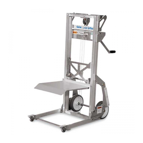
- Page 1 Service Manual Serial Number Range Load Lifter from 3395-100 to 3301-4263 from LL02-4264 to LL16G-12199 from LLG-12200 Part No. 115415 Rev A1 September 2016...
-
Page 2: Find A Manual For This Model
Copyright © 1998 by Terex Corporation 115415 Rev A, April 2009 Fourth Edition, First Printing 'Genie'' is a registered trademark of Terex South Dakota. in the U.S.A. and many other countries. “Super Series” is a trademark of Terex South Dakota. -
Page 3: Revision History
September 2016 Service Manual Introduction Revision History Revision Date Section Procedure / Page / Description 4/2009 Initial Release 9/2016 Introduction Serial Number Legend Reference Examples: Section – Maintenance, B-3 Electronic Version Section – Repair Procedure, 4-2 Click on any content or procedure in the Table of Contents to view Section –... -
Page 4: Serial Number Legend
Service Manual September 2016 Introduction Serial Number Legend To August 31, 2016 1 Model 4 Sequence number 2 Model year 5 Serial label 3 Facility code 6 Serial number (stamped on winch bracket) From September 1, 2016 1 Model 4 Serial label 2 Facility code 5 Serial number (stamped on winch bracket) 3 Sequence number... -
Page 5: Safety Rules
September 2016 Service Manual Safety Rules Section 1 Safety R ules Danger Failure to obey the instructions and safety rules in this manual and the appropriate Operator's Manual on your machine will result in death or serious injury. Many of the hazards identified in the operator's manual are also safety hazards when maintenance and repair procedures are performed. - Page 6 Service Manual September 2016 Safety Rules Personal Safety Workplace Safety Any person working on or around a machine must Any person working on or around a machine must be aware of all known safety hazards. Personal be aware of all known safety hazards. Personal safety and the continued safe operation of the safety and the continued safe operation of the machine should be your top priority.
-
Page 7: Table Of Contents
September 2016 Table of Contents Introduction Introduction ......................ii Important Information ..................... ii Find a Manual for this Model .................. ii Revision History..................... iii Serial Number Legend ..................iv Section 1 Safety Rules ......................v General Safety Rules ..................... v Section 2 Specifications ....................... - Page 8 September 2016 Table of Contents Section 4 Repair Procedures ..................... 17 Base Assembly....................19 1-1 How to Disassemble the Machine ..............19 1-2 How to Disassemble the Winch ..............19 Winch ssembly ....................21 1-3 How to Replace the Pulley ................23 1-4 How to Replace the Lifting Cable ..............
-
Page 9: Specifications
September 2016 Service Manual Specifications Section 2 Specific ati ons Machine Specifications Performance Specifications Height, maximum platform 5 ft 7 in Lift capacity 200 lbs 1.70 m 91 kg Height - Stowed 3 ft 9 in Machine weight 58 lbs 1.14 m 26 kg Load Platform... -
Page 10: Sae And Metric Fasteners Torque Charts
Service Manual September 2016 Specifications Load Lifter Part No. 115415... -
Page 11: Scheduled Maintenance Procedures
September 2016 Service Manual Scheduled Maintenance Procedures Machine Configuration: Section 3 Schedul ed Mai ntenance Pr ocedures Unless otherwise specified, perform each procedure with the machine in the following configuration: • Machine parked on a firm, level surface • Carriage fully lowered Observe and Obey: •... - Page 12 Service Manual September 2016 Scheduled Maintenance Procedures About This Section Maintenance Symbols Legend This section contains detailed procedures for each Note: The following symbols have been used in this scheduled maintenance inspection. manual to help communicate the intent of the instructions.
- Page 13 September 2016 Service Manual Scheduled Maintenance Procedures Pre-delivery Preparation Report The pre-delivery preparation report contains checklists for each type of scheduled inspection. Make copies for each inspection. Store completed forms as required. Maintenance Schedule The Scheduled Maintenance Procedures section and the Maintenance Inspection Report have been divided into subsections.
- Page 14 Service Manual September 2016 This page intentionally left blank. Load Lifter Part No. 115415...
-
Page 15: Pre-Delivery Preparation Report
September 2016 Service Manual Pre-Delivery Preparation Report Fundamentals Instructions It is the responsibility of the owner or dealer to Use the operator’s manual on your machine. perform the Pre-delivery Preparation. The Pre-delivery Preparation consists of The Pre-delivery Preparation is performed prior to completing the Pre-operation Inspection, the each delivery. - Page 16 Service Manual September 2016 This page intentionally left blank. Load Lifter Part No. 115415...
-
Page 17: Maintenance Inspection Report
September 2016 Service Manual Maintenance Inspection Report Model Y N R Y N R Checklist A- Rev A Checklist B Inspect the manuals Inspect welds Serial number and decals Clean channels Pre-operation Inspect and lubricate Date inspection winch Function tests Y N R Checklist C- Rev A Hour meter... - Page 18 Service Manual September 2016 This page intentionally left blank. Load Lifter Part No. 115415...
-
Page 19: Checklist A Procedures
September 2016 Service Manual Checklist A Procedures Open the operator's manual to the decals Inspect the Manuals and Decals inspection section. Carefully and thoroughly inspect all decals on the machine for legibility and damage. Genie specifications require that this procedure be performed every 8 hours or daily, whichever comes Result: The machine is equipped with all first. -
Page 20: Perform Pre-Operation Inspection
Service Manual September 2016 Checklist A Procedures Perform Pre-operation Inspection Perform Function Tests Genie specifications require that this procedure be Genie specifications require that this procedure be performed every 8 hours or daily, whichever comes performed every 8 hours or daily, whichever comes first. -
Page 21: Inspect The Pneumatic Tires And Wheels (If Equipped)
September 2016 Service Manual Checklist A Procedures Perform Function Tests Check the Brake Operation (if equipped) Genie specifications require that this procedure be performed every 8 hours or daily, whichever comes Genie specifications require that this procedure be first. performed every 8 hours or daily, whichever comes first. -
Page 22: Checklist B Procedures
Service Manual September 2016 Checklist B Procedures Clean the Channels Inspect All Welds Genie requires that this procedure be performed Genie specifications require that this procedure be every 250 hours or quarterly, whichever comes performed every 250 hours or quarterly, whichever first. -
Page 23: Inspect And Lubricate The Winch
September 2016 Service Manual Checklist B Procedures Inspect and Lubricate the Winch Genie specifications require that this procedure be performed every 250 hours or quarterly, whichever comes first. Maintaining the winch is essential to good machine performance and safe operation. An unsafe working condition exists if the winch has excessive wear and/or does not operate smoothly, free of hesitation and binding. -
Page 24: Checklist C Procedures
Service Manual September 2016 Checklist C Procedures Replace the Winch Brake Disks and Lubricate the Winch Shaft Genie specifications require that this procedure be performed every 1000 hours or annually, whichever comes first. Maintaining the winch is essential to good machine performance and safe operation. -
Page 25: Repair Procedures
September 2016 Service Manual Repair Procedures Machine Configuration: Section 4 Repair Pr oc edures Unless otherwise specified, perform each repair procedure with the machine in the following configuration: • Machine parked on a firm, level surface • Carriage fully lowered Observe and Obey: •... - Page 26 Service Manual September 2016 Repair Procedures About This Section Symbols Legend Safety alert symbol—used to alert Most of the procedures in this section should only personnel to potential personal be performed by trained service professional in a injury hazards. Obey all safety suitably equipped workshop.
-
Page 27: Base Assembly
September 2016 Service Manual Base Assembly Remove the inner frame stop angle mounting fasteners from the outer frame channels and How to Disassemble the Machine remove the inner frame stop angle from the outer frame channels. Using proper lifting techniques, lay the 10 Remove the winch plate mounting fasteners machine on a table or other suitable work from the outer frame channels and remove the... - Page 28 Service Manual September 2016 Base Assembly How to Assemble the Winch How to Disassemble the Winch Clean and inspect the winch components before installing. Fully lower the carriage. Note: Refer to the illustration, Winch Assembly, for Remove the cable retaining fastener from the an exploded view.
- Page 29 September 2016 Service Manual Repair Procedures Winch Assembly Part No. 115415 Load Lifter...
- Page 30 Service Manual September 2016 Repair Procedures Winch Assembly Index Index Description Description Screw, Bushing Weld Nut Flat washer, Winch Mounting Bracket Winch Drum Lock Washer Brake Disk Roll Pin Ratchet Gear Handle Assembly Brake Disk Screw, Pinion Plate Nylock nut, Pinion Shaft Spacer Outer Frame Pulley Winch Mounting Bracket Spacer...
-
Page 31: Winch Ssembly
September 2016 Service Manual Winch Assembly How to Replace the Lifting Cable How to Replace the Pulley Fully lower the carriage. Bodily injury hazard. Cables can fray. Always wear adequate Unwind the cable from the winch drum. Do not hand protection when handling remove the cable. -
Page 32: How To Replace The Glide Buttons
Service Manual September 2016 Winch Assembly Facing the winch side of the machine, thread How to Adjust the Glide Buttons the cable through the winch mounting plate. Pull all the cable through the plate. Using proper lifting techniques, lay the 10 Wrap the cable clockwise around the winch machine on a table or other suitable work drum. -
Page 33: How To Adjust The Brake (If Equipped)
September 2016 Service Manual Winch Assembly How to Adjust the Brake Rotate the brake pedal to the up position (brake unlocked). Loosen the clamping bolts from all three of the brake cams. Rotate both of the wheel-brake cams until they contact the tires.
Need help?
Do you have a question about the Genie Load Lifter and is the answer not in the manual?
Questions and answers