
Related Manuals for Terex Genie Super Series


Summary of Contents for Terex Genie Super Series
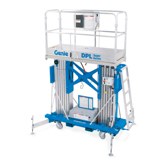
- Page 1 Service Manual Serial Number Range DPL-25S from 1596-101 to 1501-915 from DPL02-916 DPL-30S to DPL16-2311 from DPL16G-2312 to DPL16G-2599 DPL-35S from DPLG-2600 Super Series Part No. 40462 Rev A6 September 2016...
- Page 2 Readers are encouraged to notify Genie of errors First Edition, First Printing, August 1996 and send in suggestions for improvement. All Genie is a registered trademark of Terex South communications will be carefully considered for Dakota, Inc in the USA and many other future printings of this and all other manuals.
- Page 3 September 2016 Serial Number Legend To August 31, 2016 DPL 16 G - 1234 DPL16G-1234 Serial number: Model: 01/02/2010 2016 Manufacture date: Model year: Elec/Hydr Schematic: Power supply voltage/Pneumatic Pressure: Nominal Power: Machine unladen weight: Max Load: Occupants and Equipment must not exceed: Maximum allowable inclination of the chassis: Maximum Wind Speed: Indoor:...
- Page 4 Section 1 - Safety Rules September 2016 Safety Rules Danger Failure to obey the instructions and safety rules in this manual and the Genie DPL Super Series Operator's Manual will cause death or serious injury. Many of the hazards identified in the operator’s manuals are also safety hazards when maintenance and repair procedures are performed.
- Page 5 September 2016 Section 1 - Safety Rules SAFETY RULES Personal Safety Workplace Safety Any person working on or around a machine must Be sure to keep sparks, flames and be aware of all known safety hazards. Personal lighted tobacco away from flammable and safety and the continued safe operation of the combustible materials like battery gases.
-
Page 6: Table Of Contents
September 2016 Table of Contents Introduction Important Information ...................... ii Section One Safety Rules General Safety Rules ..................... iv Section Two Specifications DPL-25S ........................2 - 1 DPL-30S ........................2 - 1 DPL-35S ........................2 - 1 Bolt Torque Specification ..................2 - 2 Section Three Scheduled Maintenance Inspections Introduction ....................... - Page 7 September 2016 TABLE OF CONTENTS Section Four Scheduled Maintenance Procedures, continued A-12 Inspect the Lifting Chains and Idler Wheels ............ 4 - 6 A-13 Inspect the Breather Cap ................4 - 6 Inspect the Electrical Wiring ................4 - 7 Inspect All Welds ....................
- Page 8 September 2016 TABLE OF CONTENTS Section Six Schematics Introduction ....................... 6 - 1 Electrical Legend ...................... 6 - 2 Hydraulic Legend ...................... 6 - 3 Electrical Schematic - DPL Super Series DC - All Models (before serial number DPL07-1499) ................. 6 - 5 Electrical Schematic - DPL Super Series DC - ANSI Models (after serial number DPL07-1498) ................
- Page 9 September 2016 TABLE OF CONTENTS Section Seven Repair Procedures Introduction ....................... 7 - 1 Base Assembly Interlocks ......................7 - 2 Platform Manual Lowering Cable ..............7 - 2 How to Check the Resistance of a Valve Coil ..........7 - 3 Ground Control Box How to Test the Transformer - AC Models ............
-
Page 10: Specifications
September 2016 Section 2 - Specifications Specifications Model DPL-25S DPL-30S DPL-35S 31 ft 4 in 36 ft 40 ft 9 in Height, 9.5 m 11 m 12.4 m maximum working Height, 25 ft 4 in 30 ft 34 ft 9 in maximum platform 7.7 m 9.2 m... -
Page 11: Bolt Torque Specification
Section 2 - Specifications September 2016 SPECIFICATIONS Bolt Torque Specifications Size Threads SAE Grade 5 Bolts SAE Grade 8 Bolts per inch Torque - Dry Torque - Dry Torque - Dry Torque - Dry Torque - Dry Torque - Dry inch-pounds foot-pounds Newton meters... -
Page 12: Scheduled Maintenance Inspections
September 2016 Section 3 - Scheduled Maintenance Inspections Scheduled Maintenance Inspections About This Section Dealer Tools are New parts service required required suggested Schedule There are three types of maintenance inspections that must be performed according to a schedule— daily, quarterly and annual. To account for repeated procedures, the Maintenance Tables and Observe and Obey: the Maintenance Inspection Report have been... - Page 13 Section 3 - Scheduled Maintenance Inspections September 2016 Maintenance Tables Table A Dealer Tools are New parts service required required suggested Inspect the Operator's and Responsibility Manuals Inspect the Decals and Placards Inspect for Damage and Loose or Missing Parts Check for Hydraulic Leaks Check the Auxiliary Platform Lowering Operation Check the Manual Platform Lowering Operation...
- Page 14 September 2016 Section 3 - Scheduled Maintenance Inspections MAINTENANCE TABLES Table B Dealer Tools are New parts service required required suggested — Complete all procedures in Table A Inspect the Electrical Wiring Inspect All Welds Check the Lifting Chain Adjustments Check the Battery - DC Models Clean and Lubricate the Columns Test the Lifting Capacity...
- Page 15 Section 3 - Scheduled Maintenance Inspections September 2016 MAINTENANCE TABLES Table C Dealer Tools are New parts service required required suggested — Complete all procedures in Table A and Table B Inspect and Lubricate the Casters and Wheels Inspect the Mast Assembly for Wear Lubricate the Lifting Chains Replace the Hydraulic Oil Replace the Auxiliary Platform Lowering Batteries...
-
Page 16: Maintenance Inspection Report
September 2016 Section 3 - Scheduled Maintenance Inspections Maintenance Inspection Report Model Checklist A Y N R Checklist B Y N R Dealer Tools are New parts service Refer to Table A Refer to Table B Serial number required required suggested Operator's Electrical wiring... - Page 17 Section 3 - Scheduled Maintenance Inspections September 2016 Dealer Tools are New parts service required required suggested This page intentionally left blank. 3 - 6 DPL-25S 30S • DPL-35S Super Series Part No. 40462...
-
Page 18: Scheduled Maintenance Procedures
September 2016 Section 4 - Scheduled Maintenance Procedures Scheduled Maintenance Procedures About This Section This section contains detailed procedures for each scheduled maintenance inspection. Each procedure includes a description, safety warnings and step-by-step instructions. Observe and Obey: Symbols Legend Maintenance inspections shall be completed by Indicates the presence of a hazard a person trained and qualified on the that will cause death or serious... -
Page 19: Inspect The Operator's And Responsibility Manuals
Section 4 - Scheduled Maintenance Procedures September 2016 Table A Procedures 1 Refer to the Decals section in the Genie DPL Super Series Operator's Manual and use the Inspect the Operator’s and decal list and illustrations to determine that all Responsibility Manuals decals and placards are in place. -
Page 20: Check For Hydraulic Leaks
September 2016 Section 4 - Scheduled Maintenance Procedures TABLE A PROCEDURES 3 Activate the auxiliary platform lowering button at the ground controls. Check for Hydraulic Leaks Result: Platform should lower. Detecting hydraulic fluid leaks is essential to 4 Reconnect the power and raise the platform operational safety and good machine performance. -
Page 21: Inspect The Battery And Battery Charger - Dc Models
Section 4 - Scheduled Maintenance Procedures September 2016 TABLE A PROCEDURES Inspect the Battery and Battery Inspect the Columns for Damage Charger - DC Models Detection of damage to columns is essential for safe machine operation. An unsafe working Proper battery and charger condition is essential to condition exists if the columns are damaged and good machine performance and operational safety. -
Page 22: Check The Interlock System For Proper Operation
September 2016 Section 4 - Scheduled Maintenance Procedures TABLE A PROCEDURES 1 Visually inspect the cables and components for A-11 the following: Test the Power and • Frayed or broken wire strands Function Controls • Kinks in the cables • Corrosion Testing the machine functions and the Emergency •... -
Page 23: Inspect The Lifting Chains And Idler Wheels
Section 4 - Scheduled Maintenance Procedures September 2016 TABLE A PROCEDURES A-12 A-13 Inspect the Lifting Chains and Inspect the Breather Cap Idler Wheels The hydraulic reservoir is a breathing-type reservoir. The breather cap has an internal air filter Maintaining the lifting chains and idler wheels in that can clog and may cause the power unit to good condition is essential to safe machine operate improperly. -
Page 24: Inspect The Electrical Wiring
September 2016 Section 4 - Scheduled Maintenance Procedures Table B Procedures Inspect the Electrical Wiring Inspect All Welds Maintaining electrical wiring in good condition is Weld inspections are essential to safe machine essential to safe operation and good machine operation and good machine performance. Failure performance. -
Page 25: Check The Lifting Chain Adjustments
Section 4 - Scheduled Maintenance Procedures September 2016 TABLE B PROCEDURES Check the Lifting Chain Check the Battery - DC Models Adjustments Proper battery condition is essential to good machine performance and operational safety. Maintaining proper adjustment of the lifting chains Improper fluid levels or damaged cables and is essential to safe machine operation. -
Page 26: Clean And Lubricate The Columns
September 2016 Section 4 - Scheduled Maintenance Procedures TABLE B PROCEDURES 9 Remove the battery vent caps. Check the battery acid level. If needed, replenish with Test the Lifting Capacity distilled water to the bottom of the battery fill tube. Do not overfill. Proper lifting capacity is essential to safe machine operation. -
Page 27: Test The Power-To-Platform Operation
Section 4 - Scheduled Maintenance Procedures September 2016 TABLE B PROCEDURES Test the Power To Platform Adjust the Sequencing Cables Operation Maintaining proper adjustment of the sequencing cables is essential for safe machine operation. An AC power to the platform is intended to be an unsafe working condition exists if the sequencing extension cord to the platform for using hand tools. -
Page 28: Inspect For Proper Outrigger Length
September 2016 Section 4 - Scheduled Maintenance Procedures TABLE B PROCEDURES Inspect for Proper Outrigger Length Proper outrigger length is essential to safe machine operation. Operating a machine with outriggers different from those originally designed for the model will result in death or serious injury. 1 Measure each outrigger and verify for proper length. -
Page 29: Inspect And Lubricate The Casters
Section 4 - Scheduled Maintenance Procedures September 2016 Table C Procedures 5 Inspect each idler wheel for the following: Inspect and Lubricate the Casters • Excessive wear on the side flanges • Unusual wear Extremely dirty conditions may require that the casters be inspected and lubricated more often. -
Page 30: Lubricate The Lifting Chains
September 2016 Section 4 - Scheduled Maintenance Procedures TABLE C PROCEDURES Lubricate the Lifting Chains Replace the Hydraulic Oil Lubricated chains are essential to good machine Replacement of the hydraulic oil is essential for performance and safe operation. Extremely dirty good machine performance and service life. -
Page 31: Replacing The Auxiliary Platform Lowering Batteries
Section 4 - Scheduled Maintenance Procedures September 2016 TABLE C PROCEDURES 11 Raise and lower the platform through three complete cycles. Add hydraulic oil if needed to Replacing the Auxiliary Platform allow platform to reach full height. Lowering Batteries Component Damage Hazard. Do not allow the hydraulic reservoir to 1 Turn the machine off and remove the key. -
Page 32: Troubleshooting Flow Charts
September 2016 Section 5 - Troubleshooting Flow Charts Troubleshooting Flow Charts Before Troubleshooting: Read, understand and obey the safety rules and operating instructions printed in the Genie DPL Super Series Operator's Manual . Be sure that all necessary tools and test equipment are available and ready for use. - Page 33 Section 5 - Troubleshooting Flow Charts September 2016 TROUBLESHOOTING FLOW CHARTS About This Section General Repair Process When a malfunction is discovered, the flow charts in this section will help a service professional Malfunction Identify Troubleshoot pinpoint the cause of the problem. To use this discovered symptoms section, basic hand tools and certain pieces of test...
-
Page 34: Power Light Will Not Turn On - Ac Models
September 2016 Section 5 - Troubleshooting Flow Charts Chart 1 Power Light Will Check the power supply 0V AC Plug into a different with a voltage meter. power supply and Not Turn On - recheck the voltage. AC Models 110V AC Be sure the keyswitch is Check the voltage at in the appropriate... - Page 35 Section 5 - Troubleshooting Flow Charts September 2016 CHART 1 Check the voltage at Repair the transformer Continued from the 0V AC terminals 1 and 3 of 13 wires OR replace the previous page. pole terminal strip (J1). transformer. Put Pos. lead of voltage meter on terminal 1 and Neg.
-
Page 36: Power Light Will Not Turn On - Dc Models
September 2016 Section 5 - Troubleshooting Flow Charts Chart 2 Power Light Will Check the battery pack Charge the battery OR 0V DC voltage. check the battery Not Turn On - condition and replace a bad battery. DC Models 12V DC Be sure the keyswitch is in the appropriate Check the voltage at... - Page 37 Section 5 - Troubleshooting Flow Charts September 2016 CHART 2 Check the voltage on Continued from the 12V DC both sides of the 5amp previous page. on one P.C. board fuse. Put side Replace the 5amp fuse. Neg. lead of voltage meter on grounding terminal 10 of the 13 pole terminal strip (J1).
-
Page 38: Interlock Lights Will Not Turn On
September 2016 Section 5 - Troubleshooting Flow Charts Chart 3 Interlock light off Refer to either Chart 1 or Check the power light. Chart 2. Lights Will light on Not Turn On Check for power at Be sure the terminal 8 (black wire) on keyswitch is in the the 13 pole terminal strip (J1) located in the ground... - Page 39 Section 5 - Troubleshooting Flow Charts September 2016 CHART 3 If LED 2 is not on, check Inspect the outrigger Repair or replace Continued from the for power at the wire nut interlock contacts and the damaged interlock previous page. where the red wire from 0V DC base interlock contacts...
- Page 40 September 2016 Section 5 - Troubleshooting Flow Charts CHART 3 If LED 1 is not on, check Inspect the outrigger Repair or replace Continued from the 0V DC for power at the wire nut interlock contacts and the damaged interlock previous page.
-
Page 41: Machine Will Not Lift - Ac Models
Section 5 - Troubleshooting Flow Charts September 2016 Chart 4 Machine Will In ground control box, check for power at Not Lift - AC terminal 9 (red wire) of 13 0V DC pole terminal strip (J1). Replace the P.C. board. Models Put Neg. - Page 42 September 2016 Section 5 - Troubleshooting Flow Charts CHART 4 While pushing in and Replace the red wire Continued from the holding the control (because of open circuit) 0V DC previous page. activate switch, check for between the control power at terminal 4 of the activate switch contact up switch contact.
- Page 43 Section 5 - Troubleshooting Flow Charts September 2016 CHART 4 Perform a continuity test Continued from the across the motor continuity Replace the motor previous page. contactor coil (terminals 1 contactor. and 0). continuity Check for 110 volts AC at the common terminals 0V AC Replace faulty circuit (white and black wires) of...
-
Page 44: Machine Will Not Lift, But Power Unit Will Operate - Ac Models
September 2016 Section 5 - Troubleshooting Flow Charts Chart 5 Machine Will While pushing in the While pushing in the control activate switch control activate switch Not Lift, But and activating the up and activating the up function, hold both function, hold both Power Unit switches and check for... - Page 45 Section 5 - Troubleshooting Flow Charts September 2016 CHART 5 On the power unit, Continued from the remove and inspect the previous page. N.O. valve for contamination or damage. Clean, repair or replace valve and then perform pressure test again. less than 1800 psi Adjust the pressure relief valve.
-
Page 46: Machine Will Not Lift - Dc Models
September 2016 Section 5 - Troubleshooting Flow Charts Chart 6 Machine Will Check for power at terminal 9 (red wire) of 13 Not Lift - DC pole terminal strip (J1). 0V DC Replace the P.C. board. Put Neg. lead of voltage Models meter on terminal 10 (ground terminal). - Page 47 Section 5 - Troubleshooting Flow Charts September 2016 CHART 6 While pushing in and Replace the red wire Continued from the holding the control (because of open circuit) previous page. 0V DC activate switch, check for between the control power at terminal 4 of the activate switch contact up switch contact.
- Page 48 September 2016 Section 5 - Troubleshooting Flow Charts CHART 6 While pushing in the Relocate the Neg. lead of 0V DC Repair open circuit in the Continued from the control activate switch the voltage meter at red wire. previous page. and activating the up terminal 10 (green/yellow 0V DC...
-
Page 49: Machine Will Not Lift, But Power Unit Will Operate - Dc Models
Section 5 - Troubleshooting Flow Charts September 2016 Chart 7 Machine Will While pushing in the control activate switch Not Lift, But and activating the up function, hold both Replace or repair the Power Unit switches and check for white wire between the input voltage at the N.O. - Page 50 September 2016 Section 5 - Troubleshooting Flow Charts CHART 7 On the power unit, Continued from the remove and inspect the previous page. N.O. valve for contamination or damage. Clean, repair or replace valve and then perform pressure test again. less than 1800 psi Adjust the pressure relief valve.
-
Page 51: Machine Will Not Lower - Up Function Operates
Section 5 - Troubleshooting Flow Charts September 2016 Chart 8 Machine Will While pushing in the Check the resistance of infinite Replace the coil because 12V DC control activate switch the N.C. down valve ohms of an open circuit. Not Lower - and activating the down coils. - Page 52 September 2016 Section 5 - Troubleshooting Flow Charts CHART 8 Activate the down Continued from the Replace the N.O. down function and check the 0V DC previous page. contact block because of voltage at terminal 4 (blue an open circuit. wire) of the N.O.
-
Page 53: Platform Will Not Hold In Up Position
Section 5 - Troubleshooting Flow Charts September 2016 Chart 9 Platform Will Activate the platform up function while Not Hold In platform simultaneously activating Inspect the hydraulic holds up the manual lowering system for Up Position valve. Test the unit. contamination. -
Page 54: Power Unit Will Not Lift Rated Load
September 2016 Section 5 - Troubleshooting Flow Charts Chart 10 Power Unit Check the power source. Charge the battery OR Note on DC models the check battery condition Will Not Lift low battery indicator (red voltage and replace bad battery LED) light would be on OR use the appropriate Rated Load... - Page 55 Section 5 - Troubleshooting Flow Charts September 2016 Chart 11 Auxiliary Check the low auxillary battery indicator (red Platform Replace the 8 -1.5V, AA LED) light. If on, it is size batteries. showing a low voltage Lowering condition. Will Not Operate Check the auxillary lowering battery holder to...
- Page 56 September 2016 Section 6 • Schematics Schematics About This Section There are two groups of schematics in this section. Electrical Schematics Electrocution/burn hazard. Contact with electrically charged circuits Observe and Obey: may result in death or serious injury. Remove all rings, watches Troubleshooting and repair procedures shall be and other jewelry.
-
Page 57: Electrical Legend
Section 6 • Schematics September 2016 Electrical Legend N.O. TRANSFORMER LEVEL SENSOR RD/YL CIRCUIT BOARD Limit Switch Transformer LEVEL SENSOR Level Sensor Wire with MOTOR Switch or Button description Motor Circuits crossing Solenoid Valve Toggle Switch no connection with Diode Battery Charger Red Emergency Pressure Switch... -
Page 58: Hydraulic Legend
September 2016 Section 6 • Schematics Hydraulic Legend 2 position 2 way directional valve Motor Pump Filter Pressure compensated Solenoid operated Adjustable relief valve flow control dump valve Cylinder Check Valve Part No. 404632 DPL-25S • DPL-30S • DPL-35S Super Series 6 - 3... - Page 59 Section 6 • Schematics September 2016 WIRE COLOR LEGEND Color Description Blue Black Note: Use this legend GN/YL Green/Yellow Orange for the schematic on the opposing page. White Yellow 6 - 4 DPL-25S • DPL-30S • DPL-35S Super Series Part No.
-
Page 60: Electrical Schematic - Dpl Super Series Dc - All Models
September 2016 Section 6 • Schematics Electrical Schematic DPL Super Series DC Models (before serial number DPL07-1499 Part No. 40462 DPL-25S • DPL-30S • DPL-35S Super Series 6 - 5... -
Page 61: (Before Serial Number Dpl07-1499)
Section 6 • Schematics September 2016 Electrical Schematic DPL Super Series DC Models (before serial number DPL07-1499) ABBREVIATION LEGEND Item Description Battery B2 = 12V Battery B4 = 8 AA Batteries Power supply AC Enclosure EN1 = Platform control box EN2 = Ground control box EN4 = Power to platform GFCI receptacle Fuse, 175 AMP... -
Page 62: (After Serial Number Dpl07-1498)
September 2016 Section 6 • Schematics Electrical Schematic DPL Super Series DC Models (after serial number DPL07-1498) RD/BLK PLATFORM MODE SWITCH EMERGENCY 16.0V DC INPUT STOP BASE MODE CENTER TAP INPUT 12V DC POWER INPUT PLATFORM NEGATIVE 12V DC AUX. INPUT 16.0V DC INPUT N.C. -
Page 63: (After Serial Number Dpl07-1498)
Section 6 • Schematics September 2016 Electrical Schematic DPL Super Series DC Models (after serial number DPL07-1498) Note: Use these 2 legends for the schematic on the opposing page. - Page 64 September 2016 Section 6 • Schematics Electrical Schematic DPL Super Series DC CE Models (after serial number DPL07-1498) RD/BLK PLATFORM MODE SWITCH GROUND CONTROL EMERGENCY 16.0V DC INPUT STOP BASE MODE CENTER TAP INPUT 12V DC POWER INPUT PLATFORM NEGATIVE 12V DC AUX. INPUT 16.0V DC INPUT N.C.
- Page 65 Section 6 • Schematics September 2016 Electrical Schematic DPL Super Series DC CE Models (after serial number DPL07-1498) Note: Use this legend for the schematic on the opposing page.
-
Page 66: (Before Serial Number Dpl07-1499)
September 2016 Section 6 • Schematics Electrical Schematic DPL Super Series AC Models (before serial number DPL07-1499) Part No. 40462 DPL-25S • DPL-30S • DPL-35S Super Series 6 - 8... - Page 67 Section 6 • Schematics September 2016 Electrical Schematic DPL Super Series AC Models (before serial number DPL07-1499) Note: Use these 2 legends for the schematic on the opposing page.
-
Page 68: (From Serial Number Dpl07-1499 To Dpl07-1562)
September 2016 Section 6 • Schematics Electrical Schematic DPL Super Series AC Models (from serial number DPL07-1499 to DPL07-1562) RD/BLK PLATFORM MODE SWITCH FOR 240 V OPERATION GROUND CONTROL BOX JUMPER BROWN TO WHITE THROUGH TERMINAL STRIP TRANSFORMER AND LEAVE BLACK UNCONNECTED AS SHOWN EMERGENCY 16.0V AC INPUT... - Page 69 Section 6 • Schematics September 2016 Electrical Schematic DPL Super Series DC CE Models (from serial number DPL07-1499 to DPL07-1562) Note: Use these 2 legends for the schematic on the opposing page.
-
Page 70: (After Serial Number Dpl07-1562)
September 2016 Section 6 • Schematics Electrical Schematic DPL Super Series AC Models (after serial number DPL07-1562) *N28 FOR 240 V OPERATION JUMPER BROWN TO WHITE THROUGH TERMINAL STRIP AND LEAVE PLATFORM BLACK UNCONNECTED AS SHOWN MODE CB4 = 8A, CB9 = 3A) FOR 120V OPERATION JUMPER BROWN TO SWITCH BLACK AND BLUE TO WHITE AS... -
Page 71: (After Serial Number Dpl07-1562)
Section 6 • Schematics September 2016 Electrical Schematic DPL Super Series AC Models (after serial number DPL07-1562) Note: Use these 2 legends for the schematic on the opposing page. -
Page 72: Electrical Schematic Dpl Super Series Ac Ce Models
September 2016 Section 6 • Schematics Electrical Schematic DPL Super Series AC CE Models (from serial number DPL07-1499 to DPL07-1562) RD/BLK GN/YL N.C. PLATFORM N.C. J BOX PLATFORM DOWN PLATFORM MODE DOWN SWITCH FOR 240 V OPERATION GROUND CONTROL BOX J BOX JUMPER BROWN TO WHITE THROUGH TERMINAL STRIP... - Page 73 Section 6 • Schematics September 2016 Electrical Schematic DPL Super Series AC Models (from serial number DPL07-1499 to DPL07 -1562) Note: Use these 2 legends for the schematic on the opposing page.
- Page 74 September 2016 Section 6 • Schematics Electrical Schematic DPL Super Series AC CE Models (after serial number DPL07-1562) *N28 GN/YL N.C. FOR 240 V OPERATION PLATFORM N.C. JUMPER BROWN TO WHITE J BOX DOWN PLATFORM THROUGH TERMINAL STRIP AND LEAVE DOWN PLATFORM BLACK UNCONNECTED AS SHOWN...
- Page 75 Section 6 • Schematics September 2016 Electrical Schematic DPL Super Series AC CE Models (after serial number DPL07-1562)
- Page 76 Section 6 • Schematics September 2016 Hydraulic Schematic DPL Super Series ANSI Models Part No. 40462 DPL-25S • DPL-30S • DPL-35S Super Series 6 - 13...
- Page 77 Section 6 • Schematics September 2016 Hydraulic Schematic DPL Super Series ANSI Models...
- Page 78 Section 6 • Schematics September 2016 Hydraulic Schematic DPL Super Series CE Models Part No. 40462 DPL-25S • DPL-30S • DPL-35S Super Series 6 - 14...
- Page 79 Section 6 • Schematics September 2016 Hydraulic Schematic DPL Super Series CE Models...
- Page 80 September 2016 Section 7 - Repair Procedures Repair Procedures About This Section Most of the procedures in this section should only be performed by a trained service professional in a suitably equipped workshop. Select the appropriate repair procedure after troubleshooting the problem.
-
Page 81: Base Assembly
Section 7 - Repair Procedures September 2016 Base Assembly Interlocks Base Components The interlock contact brackets indicate proper How to Adjust the Platform installation of the outriggers and only allow the Manual Lowering Cable machine to operate when the outriggers are properly installed and adjusted. -
Page 82: How To Check The Resistance Of A Valve Coil
September 2016 Section 7 - Repair Procedures BASE ASSEMBLY How to Check the Resistance of a Valve Coil The valve coil is located at the bottom of the hydraulic lift cylinder. 1 Lower the platform, turn the machine off and remove the key. -
Page 83: Ground Control Box
Section 7 - Repair Procedures September 2016 Ground Control Box How to Test the Transformer How to Test the AC Contactor - AC Models - AC Models 1 Fully lower the platform, turn the key switch off 1 Fully lower the platform, turn the key switch off and disconnect the power supply. - Page 84 September 2016 Section 7 - Repair Procedures This page intentionally left blank. Part No. 40462 DPL-25S • DPL-30S • DPL-35S Super Series 7 - 5...
-
Page 85: Hydraulic Power Units
Section 7 - Repair Procedures September 2016 Hydraulic Power Units Hydraulic Power Unit Components - AC Models Index Description Function 115-230V AC electric motor ......Single phase - 2850/3450 rpm, 50/60 Hz Capacitor ............Motor start circuit Pressure relief valve ......... Hydraulic relief valve adjustment Solenoid operated N.O. - Page 86 September 2016 Section 7 - Repair Procedures HYDRAULIC POWER UNITS Part No. 40462 DPL-25S • DPL-30S • DPL-35S Super Series 7 - 7...
-
Page 87: Hydraulic Power Unit Components - Dc Models
Section 7 - Repair Procedures September 2016 HYDRAULIC POWER UNITS Hydraulic Power Unit Components - DC Models Index Description Function 12V DC electric motor ........12V DC standard duty 1 terminal 180 amp at 2650 psi (183 bar) Electric motor starter solenoid ......Relay connecting power supply to electric motor Pressure relief valve ......... - Page 88 September 2016 Section 7 - Repair Procedures HYDRAULIC POWER UNITS Part No. 40462 DPL-25S • DPL-30S • DPL-35S Super Series 7 - 9...
-
Page 89: How To Remove The Hydraulic Power Unit - Ac Models
Section 7 - Repair Procedures September 2016 HYDRAULIC POWER UNITS How to Remove the Hydraulic How to Remove the Hydraulic Power Unit - AC Models Power Unit - DC Models 1 Fully lower the platform, turn the machine off, 1 Fully lower the platform, turn the machine off, remove the key and disconnect the power remove the key and disconnect the power source. -
Page 90: How To Remove The Hydraulic Pump
September 2016 Section 7 - Repair Procedures HYDRAULIC POWER UNITS How to Remove the Hydraulic Pump 1 Fully lower the platform, turn the machine off and remove the key. 2 Remove the base cover from the power unit. 3 Remove the drain plug from the hydraulic reservoir and completely drain the reservoir into a container. -
Page 91: How To Adjust The Pressure Relief Valve
Section 7 - Repair Procedures September 2016 HYDRAULIC POWER UNITS 12 The power unit should not be able to lift the platform. If the power unit lifts the platform, turn How to Adjust the Pressure the relief valve clockwise or counterclockwise Relief Valve until the adjustment is correct. -
Page 92: How To Check The Resistance Of A Valve Coil
September 2016 Section 7 - Repair Procedures HYDRAULIC POWER UNITS How to Check the Resistance How to Test the Motor Start of a Valve Coil Solenoid - DC Models 1 Fully lower the platform, turn the machine off Electrocution/burn hazard. Contact and remove the key. -
Page 93: Mast Assembly
Section 7 - Repair Procedures September 2016 Mast Assembly DPL-25S DPL-30S DPL-35S Mast Components number 4 column idler wheel assembly number 4 column number 3 column idler wheel assembly carriage number 2 column idler wheel assembly number 5 column number 1 column number 5 column idler wheel assembly number 2 column number 6 column idler wheel assembly... -
Page 94: How To Remove A Lift Cylinder
September 2016 Section 7 - Repair Procedures MAST ASSEMBLY 3 Remove the cylinder mounting fasteners from the cylinder barrel end. Lift Cylinder 4 Loosen the cylinder bracket mounting fasteners. How to Remove a Lift Cylinder This procedure requires specific repair skills, lifting equipment and a suitable workshop. -
Page 95: How To Remove A Mast Assembly
Section 7 - Repair Procedures September 2016 MAST ASSEMBLY 8 Tag, disconnect and cap the lift cylinder hydraulic hoses. Remove the flow control valve How to Remove a Mast Assembly from the cylinder. Plug the cylinder ports. This procedure requires specific Bodily injury hazard. - Page 96 September 2016 Section 7 - Repair Procedures MAST ASSEMBLY 3 Remove the socket head retaining bolt from the 10 Slide the carriage out the bottom of the mast clevis block on the lift cylinder rod end. assembly. 11 Lay the chains out on the floor at the top of the mast.
- Page 97 Section 7 - Repair Procedures September 2016 MAST ASSEMBLY How to Assemble the Mast 13 After all the columns are together the idler wheel assemblies need to be installed. This procedure requires specific 14 Remove the tension from the lifting chains on repair skills, lifting equipment and the number 2 column by pushing the number 3 a suitable workshop.
-
Page 98: How To Adjust The Lifting Chains
September 2016 Section 7 - Repair Procedures MAST ASSEMBLY How to Adjust the Lifting Chains How to Adjust the Glide Pads When adjusting the lifting chains, it is very When adjusting the glide pads, it is very important important to maintain equal adjustment for both to maintain equal adjustment for both mast mast assemblies. -
Page 99: How To Inspect The Lifting Chains
Section 7 - Repair Procedures September 2016 MAST ASSEMBLY How to Inspect the Lifting Chains Inspection Procedure Inspection Failure Inspection Remedy Wear Count out 16 chain links When the length of the Replace both chains on and measure pin to pin 16 links (pin to pin) that column section. - Page 100 September 2016 Section 7 - Repair Procedures MAST ASSEMBLY Inspection Procedure Inspection Failure Inspection Remedy Raised pins. Replace both chains on Raised or Turned Pins Visually inspect for raised that column section. Do pins. not repair just the affected portion of the chain.
-
Page 101: Platform
Section 7 - Repair Procedures September 2016 Platform How to Remove the Platform Platform Control Box 1 Remove the cover from the platform control box How to Test the Contactors and the AC outlet to access the mounting screws. 1 Fully lower the platform, turn the key switch off and disconnect the power supply. - Page 102 September 2016 Section 7 - Repair Procedures PLATFORM How to Test Power-to-Platform GFCI outlet 1 Fully lower the platform, turn the key switch off. 2 AC and DC models: Be sure the AC power supply is properly connected. 3 Connect an AC voltage tester or a small hand tool to the platform GFCI receptacle.
- Page 103 Section 7 - Repair Procedures September 2016 This page intentionally left blank. 7 - 24 DPL-25S • DPL-30S • DPL-35S Super Series Part No. 40462...
Need help?
Do you have a question about the Genie Super Series and is the answer not in the manual?
Questions and answers