Table of Contents
Advertisement
Quick Links
CHAPTER 1
INTRODUCTION
Chapter 1
INTRODUCTION
The MS-6198 Micro ATX VA3 mainboard is a high-performance computer
®
mainboard based on VIA
VT82C694X chipset. The MS-6198 is designed
®
TM
for the Intel
Celeron
or Coppermine(FC-PGA) processor for inexpensive
business/personal desktop markets.
The Apollo Pro133A (VT82C694X) is a Socket-370 system logic north bridge
with the addition of 133 MHz capability for both the CPU and SDRAM
interfaces. Apollo Pro133A may be used to implement both desktop and
notebook personal computer systems from 66MHz to 133MHz based on
Socket-370 (Intel Celeron processors). The primary features of the Apollo
Pro133A-North Bridge are: Slot-1 or Socket-370 CPU (Front Side Bus)
Interface (66 / 100 / 133MHz), SDRAM Memory Interface (66 / 100 /
133MHz), AGP Bus Interface (66MHz), PCI Bus Interface (33MHz), Mobile
Power Management.
The VT82C686A PSIPC (PCI Super-I/O Integrated Peripheral Controller) is a
high integration, high performance, power-efficient, and high compatibility
device that supports Intel and non-Intel based processor to PCI bus bridge
functionality to make a complete Microsoft PC99-compliant PCI/ISA system.
1-1
Advertisement
Table of Contents

Related Manuals for MSI MS-6198


Summary of Contents for MSI MS-6198
- Page 1 CHAPTER 1 INTRODUCTION Chapter 1 INTRODUCTION The MS-6198 Micro ATX VA3 mainboard is a high-performance computer ® mainboard based on VIA VT82C694X chipset. The MS-6198 is designed ® for the Intel Celeron or Coppermine(FC-PGA) processor for inexpensive business/personal desktop markets.
-
Page 2: Mainboard Features
CHAPTER 1 INTRODUCTION 1.1 Mainboard Features l Socket 370 for Intel ® Celeron /Coppermine processor. l Supports 233MHz, 266MHz, 300MHz, 333MHz, 350MHz, 400MHz, 450MHz, 500MHZ, 533MHz., 550MHz, 667MHz or faster processor. Chipset l VIA ® 694X chipset. (510 BGA) - FSB @133MHz - AGP 4x and PCI plus Advanced ECC Memory Controller - Support PC100/133 SDRAM technology l VIA... - Page 3 CHAPTER 1 INTRODUCTION On-Board IDE l An IDE controller on the VIA ® VT82C686A Chipset provides IDE HDD/ CD-ROM with PIO, Bus Master and Ultra DMA 33/66 operation modes. l Can connect up to four IDE devices. On-Board Peripherals l On-Board Peripherals include: - 1 floppy port supports 2 FDD with 360K, 720K, 1.2M, 1.44M and 2.88Mbytes.
-
Page 4: Mainboard Layout
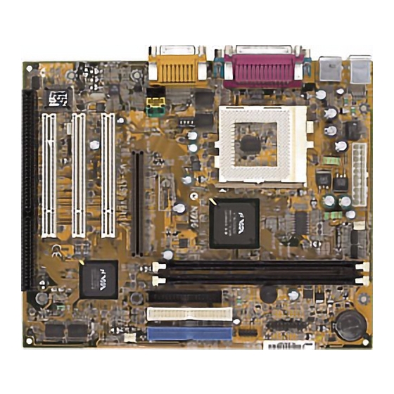
Top: LPT USB2 Bottom: COM A COM B 694X chipset Top: Midi/ Game Port Bottom: Line-Out Line-In SYSFAN AGP Slot PCI SLOT 1 VT82C686A PCI SLOT 2 JBAT1 JMDM1 JWOL1 BIOS PCI SLOT 3 ISA SLOT MS-6198 Micro ATX VA3 Mainboard... -
Page 5: Hardware Installation
HARD HARDW W W W W ARE INST HARD ARE INST ARE INST ALLA ALLA TION TION HARD HARD ARE INST ARE INSTALLA ALLA ALLATION TION TION Hardware Installation... -
Page 6: Central Processing Unit (Cpu)
CHAPTER 2 CHAPTER 2 CHAPTER 2 CHAPTER 2 CHAPTER 2 Central Processing Unit: CPU Intel Celeron /Coppermine ® processor. • • • • • CPU Installation Procedures Open Lever Sliding Plate Pin 1 White dot/ Cut edge Pin 1 Close Lever... - Page 7 HARD HARD HARDW W W W W ARE INST HARD HARD ARE INST ARE INST ARE INST ARE INSTALLA ALLA ALLA ALLA ALLATION TION TION TION TION • CPU Speed Setting: SW1 always ask your reseller for CPU specifications...
- Page 8 CHAPTER 2 CHAPTER 2 CHAPTER 2 CHAPTER 2 CHAPTER 2 • CPU Core Speed Derivation Procedure then...
-
Page 9: Memory Installation
HARD HARD HARDW W W W W ARE INST HARD HARD ARE INST ARE INST ARE INST ARE INSTALLA ALLA ALLA ALLA ALLATION TION TION TION TION Memory Installation • • • • • Memory Bank Configuration unbuffered DIMM1 DIMM2 •... - Page 10 CHAPTER 2 CHAPTER 2 CHAPTER 2 CHAPTER 2 CHAPTER 2 • • • • • Memory Installation Procedures How to install a DIMM Module Single Sided DIMM Double Sided DIMM DRAM VOLT...
- Page 11 HARD HARD HARDW W W W W ARE INST HARD HARD ARE INST ARE INST ARE INST ARE INSTALLA ALLA ALLA ALLA ALLATION TION TION TION TION • • • • • SDRAM Memory Addressing Single Double pcs. pcs. Side(S) Side(D)
-
Page 12: Back Panel
CHAPTER 2 CHAPTER 2 CHAPTER 2 CHAPTER 2 CHAPTER 2 Back Panel Mouse Connector: JKBMS1 Mouse Connector: JKBMS1 Mouse Connector: JKBMS1 Mouse Connector: JKBMS1 Mouse Connector: JKBMS1 ® ® ®... -
Page 13: Keyboard Connector: Jkbms1
HARD HARD HARDW W W W W ARE INST HARD HARD ARE INST ARE INST ARE INST ARE INSTALLA ALLA ALLA ALLA ALLATION TION TION TION TION Keyboard Connector: JKBMS1 ® USB Connectors UHCI (Universal Host Controller Interface) Universal Serial Bus root... -
Page 14: Parallel Port Connector: Lpt1
CHAPTER 2 CHAPTER 2 CHAPTER 2 CHAPTER 2 CHAPTER 2 Parallel Port Connector: LPT1 Parallel Port Connector: LPT1 Parallel Port Connector: LPT1 Parallel Port Connector: LPT1 Parallel Port Connector: LPT1 2-10... -
Page 15: Joystick/Midi Connectors
HARD HARDW W W W W ARE INST HARD ARE INST ARE INST ALLA ALLA TION TION HARD HARD ARE INST ARE INSTALLA ALLA ALLATION TION TION Serial Port Connectors: COM A and COM B Serial Port Connectors: COM A and COM B Serial Port Connectors: COM A and COM B Serial Port Connectors: COM A and COM B Serial Port Connectors: COM A and COM B... -
Page 16: Audio Port Connectors
CHAPTER 2 CHAPTER 2 CHAPTER 2 CHAPTER 2 CHAPTER 2 Audio Port Connectors Line Out Line In Line Out Line In 2-12... -
Page 17: Fan Power Connectors: Cpufan & Sysfan
HARD HARD HARDW W W W W ARE INST HARD HARD ARE INST ARE INST ARE INST ARE INSTALLA ALLA ALLA ALLA ALLATION TION TION TION TION Connectors Fan Power Connectors: CPUFAN & SYSFAN Fan Power Connectors: CPUFAN & SYSFAN Fan Power Connectors: CPUFAN &... -
Page 18: Case Connector: Jfp1
CHAPTER 2 CHAPTER 2 CHAPTER 2 CHAPTER 2 CHAPTER 2 Case Connector: JFP1 Reset Switch Power Switch 5V Standby Speaker Power LED Suspend LED Buzzer JFP1 Power Switch Reset Switch Power LED Note: Speaker HDD LED 2-14... -
Page 19: Floppy Disk Connector: Fdd
HARD HARD HARDW W W W W ARE INST HARD HARD ARE INST ARE INST ARE INST ARE INSTALLA ALLA ALLA ALLA ALLATION TION TION TION TION Floppy Disk Connector: FDD USB Front Connector: USB1 USB Front Connector: USB1 USB Front Connector: USB1 USB Front Connector: USB1 USB Front Connector: USB1 front Universal Serial Bus connector... -
Page 20: Hard Disk Connectors: Ide1 & Ide2
CHAPTER 2 CHAPTER 2 CHAPTER 2 CHAPTER 2 CHAPTER 2 Hard Disk Connectors: IDE1 & IDE2 IDE2 IDE1 IDE1 IDE2 2-16... - Page 21 HARD HARD HARDW W W W W ARE INST HARD HARD ARE INST ARE INST ARE INST ARE INSTALLA ALLA ALLA ALLA ALLATION TION TION TION TION W W W W W ak ake e e e e -Up on LAN Connector: JWOL1 -Up on LAN Connector: JWOL1 -Up on LAN Connector: JWOL1 -Up on LAN Connector: JWOL1...
-
Page 22: Power Saving Switch Connector: Jgs1
CHAPTER 2 CHAPTER 2 CHAPTER 2 CHAPTER 2 CHAPTER 2 IrDA Infrared Module Connector: J1 VCC NC IRRX GND IRTX Power Saving Switch Connector: JGS1 JGS1 2-18... -
Page 23: Aux Line In Connector: Jaux1
HARD HARD HARDW W W W W ARE INST HARD HARD ARE INST ARE INST ARE INST ARE INSTALLA ALLA ALLA ALLA ALLATION TION TION TION TION CD-In Connector: JCD1 -In Connector: JCD1 -In Connector: JCD1 -In Connector: JCD1 -In Connector: JCD1 AUX Line In Connector: JAUX1 AUX Line In Connector: JAUX1 AUX Line In Connector: JAUX1... - Page 24 CHAPTER 2 CHAPTER 2 CHAPTER 2 CHAPTER 2 CHAPTER 2 Modem-In: JPHONE 2-20...
-
Page 25: Power Supply
HARD HARDW W W W W ARE INST HARD ARE INST ARE INST ALLA ALLA TION TION HARD HARD ARE INST ARE INSTALLA ALLA ALLATION TION TION Power Supply A A A A A TX 20-pin P TX 20-pin P TX 20-pin P ower Connector: JWR1 ower Connector: JWR1... - Page 26 CHAPTER 2 CHAPTER 2 CHAPTER 2 CHAPTER 2 CHAPTER 2 Jumpers Clear CMOS Jumper: JBA Clear CMOS Jumper: JBA Clear CMOS Jumper: JBA Clear CMOS Jumper: JBAT1 Clear CMOS Jumper: JBA You can clear CMOS by shorting 2-3 pin, while the system is off.
- Page 27 HARD HARD HARDW W W W W ARE INST HARD HARD ARE INST ARE INST ARE INST ARE INSTALLA ALLA ALLA ALLA ALLATION TION TION TION TION Front Panel Audio Header: JP1 Front Panel Audio Header: JP1 Front Panel Audio Header: JP1 Front Panel Audio Header: JP1 Front Panel Audio Header: JP1 Note: For descriptions with asterisk (*) sign, please refer to page 2-25...
- Page 28 CHAPTER 2 CHAPTER 2 CHAPTER 2 CHAPTER 2 CHAPTER 2 FrontAudio RearAudio ActiveAudio FrontAudio RearAudio ActiveAudio AC97 AMPLIFIER FrontLineOutR LineNextR LineNextL FrontLineOutL PHONEJACK 2-24...
-
Page 29: Agp (Accelerated Graphics Port) Slot
HARD HARD HARDW W W W W ARE INST HARD HARD ARE INST ARE INST ARE INST ARE INSTALLA ALLA ALLA ALLA ALLATION TION TION TION TION Slots AGP (Accelerated Graphics Port) Slot AGP (Accelerated Graphics Port) Slot AGP (Accelerated Graphics Port) Slot AGP (Accelerated Graphics Port) Slot AGP (Accelerated Graphics Port) Slot PCI (Peripheral Component Interconnect) Slots... - Page 30 ® Chapter 3 ® BIOS USER’S GUIDE The system configuration information and chipset register information is stored in the CMOS RAM. This information is retained by a battery when the power is off. Enter the BIOS setup (if needed) to modify this information. The following pages will describe how to enter BIOS setup, and all about options.
-
Page 31: Enter Bios Setup
® 3.1 Enter BIOS Setup ® Enter the AMI setup Program’s Main Menu as follows: 1. Turn on or reboot the system. The following screen appears with a series of diagnostic check. AMIBIOS (C) 1999 American Megatrends Inc. A6198 VXXX XXXXXX Hit <DEL>... - Page 32 ® AMIBIOS SIMPLE SETUP UTILITIES - VERSION 1.21a (C) 1999 American Megatrends, Inc. All Rights Reserved Standard CMOS Setup Integrated Peripherals BIOS Features Setup Hardware Monitor Setup Chipset Features Setup IDE HDD Auto Detection Power Management Setup Supervisor Password PNP/PCI Configuration User Password Load BIOS Defaults Save and Exit Setup...
-
Page 33: Standard Cmos Setup
® 3.2 Standard CMOS Setup 1. Press <ENTER> on “Standard CMOS Setup” of the main menu screen . AMIBIOS SETUP - STANDARD CMOS SETUP (C)1999 American Megatrends,Inc.All Rights Reserved Date (mm/dd/yyyy): Fri Oct 29, 1999 Time (hh/mm/ss): 17:09:25 32Bit Type Size Cyln Head... -
Page 34: Bios Features Setup
® 3.3 BIOS Features Setup 1. Press <ENTER> on “BIOS Features Setup” of the main menu screen. AMIBIOS SETUP - BIOS FEATURES SETUP (C) 1999 American Megatrends, Inc. All Rights Reserved Quick Boot :Enabled DC00, 16K Shadow Disabled 1st Boot Device :Floppy 2nd Boot Device :CDROM... - Page 35 ® Description of the item on screen follows: Quick Boot ® Set this option to Enabled to permit AMI BIOS to boot within 5 seconds. This option replaces the old ABOVE 1 MB Memory Test option. The Optimal default setting is Enabled. The Fail-Safe default setting is Disabled.
-
Page 36: Floppy Drive Seek
® Floppy Drive Seek ® When this option is set to Enabled, AMI BIOS performs a Seek command on floppy drive A: before booting the system. The settings are Enabled and Disabled. The Optimal and Fail-Safe default settings are Enabled. Password Check ®... -
Page 37: System Bios Cacheable
® System BIOS Cacheable ® BIOS always copies the system BIOS from ROM to RAM for faster execution. Set this option to Enabled to permit the contents of the F0000h RAM memory segment to be written to and read from cache memory. The settings are Enabled or Disabled. -
Page 38: Chipset Features Setup
® 3.4 Chipset Features Setup 1. Press <ENTER> on “Chipset FeaturesSetup” of the main menu screen. AMIBIOS SETUP - CHIPSET FEATURES SETUP (C) 1999 American Megatrends, Inc. All Rights Reserved Set SDRAM Timing by SPD :Disabled DRAM Frequency :100Mhz SDRAM CAS# Latency DRAM Integrity Mode :Disabled CPU In Order Queue... - Page 39 ® Description of the item on screen follows: Set SDRAM Timing By SPD Choose Enabled, will automatically configure the DRAM Timing depending on the “DRAM Speed” selection. Choose Disabled, to customize the setup. SDRAM CAS# Latency When synchronous DRAM is installed, the number of clock cycles of CAS latency depends on the DRAM timing.
- Page 40 ® USB KB/Mouse Legacy Support Set this option to Enabled or Disabled USB Mouse & keyboard. The Optional and Fail-Safe default setting is Disabled. 3-11...
-
Page 41: Power Management Setup
® 3.5 Power Management Setup 1. Press <ENTER> on “Power Management Setup” of the main menu screen. AMIBIOS SETUP - POWER MANAGEMENT SETUP (C) 1999 American Megatrends, Inc. All Rights Reserved System Thermal :Ignore Compliance With O/S :Yes Thermal Slow Clock Ratio :50%-56.25% ACPI Standby State :S1/POS... - Page 42 ® Description of the item on screen follows: Compliance With O/S Set this option to Yes the operating system is support ACPI. The setting is No, the operating system is support APM. ACPI Standby State This item will set which ACPI standby type will be used. Power Management/APM Set this option to enable the chipset’s power management features and APM(Advanced Power Management).
- Page 43 ® Standby TimeOut (Minute) This option defines the continuous idle time before the system enters STANDBY mode. If any item defined in the options of “Power Down and Resume events” is enabled & active, STANDBY timer will be reloaded. When the system has entered Standby mode, any of the items that are enabled in “Wake Up Events of Doze and Standby”...
-
Page 44: Power Button Function
® Power Button Function During Suspend, if you push the switch once, the system goes into suspend mode and if you push it more than 4 seconds, the system will be turned off. During On/Off, the system will turn off once you push the switch. -
Page 45: Resume By Alarm
® Resume by Alarm This function is for setting the Date, Hour, Minute, and Second for your computer to boot up. During Disabled, you cannot use this function. During Enabled, Choose the Date, Hour, Minute, and Second: RTC Alarm Date Choose which day the system will boot up. -
Page 46: Pnp/Pci Configuration
® 3.6 PNP/PCI Configuration 1. Press <ENTER> on “PNP/PCI Configuration” of the main menu screen. AMIBIOS SETUP - PNP/PCI CONFIGURATION (C) 1999 American Megatrends, Inc. All Rights Reserved PnP Aware O/S Clear NVRAM PCI Latency Timer Primary Graphics Adapter :PCI PCI VGA Palette Snoop :Disabled DMA Channel 0... - Page 47 ® Description of the item on screen follows: Plug and Play Aware O/S Set this option to Yes if the operating system in this computer is aware of and follows the Plug and Play specification. Currently, only ® Windows 95 is PnP-aware. The settings are Yes or No. The Optimal and Fail-Safe default settings No.
-
Page 48: Dma Channel
® DMA Channel 0/1/3/5/6/7 These options specify the bus that the specified DMA channel is used. These options allow you to reserve DMAs for legacy ISA adapter cards. ® These options determine if AMI BIOS should remove a DMA from the available DMAs passed to devices that are configurable by the system BIOS. -
Page 49: Integrated Peripherals
® 3.7 Integrated Peripherals 1. Press <ENTER> on “Integrated Peripherals” of the main menu screen. AMIBIOS SETUP - INTEGRATED PERIPHERALS (C) 1999 American Megatrends, Inc. All Rights Reserved Onboard IDE :Both Onboard FDC :Auto Onboard Serial Port 1 :Auto Onboard Serial Port 2 :Auto Serial Port 2 Mode :Normal... -
Page 50: Onboard Fdc
® Description of the item on screen follows: Onboard FDC Choose Auto, for the BIOS to automatically detect the device If the ISA add-on card has Onboard FDC to be set at Disabled FDC exist Enabled none FDC exist Choose Enabled, Enabling onboard FDC. Choose Disabled, Disabling onboard FDC. - Page 51 ® Serial Port2 Mode This items allows the user to determine which InfraRed (IR) function of the onboard I/O chip. IR Duplex Mode Can be set as either Half or Full duplex. Onboard Parallel Port Choose Auto, the BIOS automatically assigned onboard parallel port to the available parallel port or disabled.
-
Page 52: Parallel Port Dma
® Parallel Port DMA This option allows user to choose DMA channel 1 to 3 for the onboard parallel port on ECP mode. Parallel Port IRQ If the onboard parallel mode is not on auto mode, the user can select the interrupt line for onboard parallel port. We suggest that the user select the interrupt for the onboard parallel port as shown below: Parallel Port IRQ Onboard parallel port set at... -
Page 53: Hardware Monitor Setup
® 3.8 Hardware Monitor Setup 1. Press <ENTER> on “Hardware Monitor Setup” of the main menu screen. AMIBIOS SETUP - Hardware Monitor Setup (C) 1999 American Megatrends, Inc. All Rights Reserved ClkGen Spread Spectrum :Enabled 5.028V -= System Monitor =- Current CPU Temperature Current System Temperature Current CPU Fan Speed... - Page 54 ® Description of the item on screen follows: Clk Spread Spectrum This item allows you to select the clock generator Spread Spectrum function. When overclocking the processor, always set this item to Disa- bled. The defualt setting is Enabled. 3-25...
-
Page 55: Ide Hdd Auto Detection
® 3.9 IDE HDD Auto Detection You can use this utility to automatically detect the characteristics of most hard drives. AMIBIOS SETUP - STANDARD CMOS SETUP (C)1999 American Megatrends,Inc.All Rights Reserved Date (mm/dd/yyyy): Fri Oct 29, 1999 Time (hh/mm/ss): 17:09:25 32Bit Type Size... -
Page 56: Supervisor/User Password
® 3.10 Supervisor/User Password This Main Menu item lets you configure the system so that a pass- word is required each time the system boots or an attempt is made to enter the Setup program. Supervisor Password allows you to change all CMOS settings but the User Password setting doesn’t have this function. -
Page 57: Audio Features
Chapter 4 VIA CHIPSET DRIVER 1. Overview The MS-6198 is paired with the VIA VT82C686A south bridge. Highly advanced, the south bridge combines an integrated 2D/3D engine with DVD hardware acceleration, AC-97 audio support for SoundBlaster Pro and FM synthesis legacy audio. - Page 58 CHAPTER 4 VIA CHIPSET DRIVER 2. Driver Setup & Usage Procedures for Windows ® Insert the CD-title into your CD-ROM drive. The CD will auto-run and will display the four icons in the monitor “VIA Chipset Drivers”, “VIA AC97 PCI Sound Drivers” and “Download VIA Drivers”. In order to install the drivers correctly, you must install the “Via Chipset Drivers”...
- Page 59 CHAPTER 4 VIA CHIPSET DRIVER Step 8: The setup program will let you choose between “Install VIA Chipset Functions Registry” or “Uninstall VIA Chipset Functions Registry”. Please select “Install VIA Chipset Functions Registry” and then click “Next”. Step 9: The setup program will let you choose between “Install VIA IRQ Routing Miniport Driver”...
- Page 60 CHAPTER 4 VIA CHIPSET DRIVER VIA AC97 PCI Sound Drivers installation procedure: Step 1: Insert the provided CD_ROM disk into the CD-ROM drive. Step 2: Look for the CD_ROM drive, double click on the CD_ROM icon. This will show the setup screen. Step 3: Click on “VIA AC97 PCI Sound Drivers”...
-
Page 61: Windows Nt
CHAPTER 4 VIA CHIPSET DRIVER 3. Windows NT 4.0 ® ® Install Windows NT 4.0 Service Pack 3 or the latest version before installing the VIA drivers. Insert the CD-title in the CD-ROM drive. The CD will auto-run and will display four icons on the screen “VIA Chipset Drivers”, “VIA AC97 PCI Sound Drivers”and “Download VIA Drivers”. - Page 62 CHAPTER 4 VIA CHIPSET DRIVER 3.2 VIA AC97 PCI Sound Drivers Installation Procedure: Step 1: Insert the provided CD_ROM disk into the CD-ROM drive. Step 2: Look for the CD_ROM drive, double click on the CD_ROM icon. This will show the setup screen. Step 3: Click on “VIA AC97 PCI Sound Drivers”...
Need help?
Do you have a question about the MS-6198 and is the answer not in the manual?
Questions and answers