Table of Contents
Advertisement
CHAPTER 1
INTRODUCTION
Chapter 1
INTRODUCTION
The MS-6178 Micro ATX WH5 mainboard is a high-performance computer
®
mainboard based on Intel
810 (810/810 DC100/810e) chipset. The MS-6178
®
TM
is designed for the Intel
Pentium II/III or Celeron
processor for inexpen-
sive business/personal desktop markets.
®
The Intel
810 chipset is the first generation Integrated Graphics chipset for
®
TM
the Intel
Celeron
processor. The graphics accelerator architecture
consists of dedicated multi-media engines executing in parallel to deliver
high performance 3D, 2D, and motion compensation video capabilities. An
integrated centralized memory arbiter allocates memory bandwidth to
multiple system agents to optimize system memory utilization. A new
chipset component interconnect, the hub interface, is designed into the Intel
810 chipset to provide an efficient communication channel between the
memory controller hub and I/O hub controller.
®
The series of Intel
810 chipset contains three core components: the
Graphics and Memory Controller Hub (GMCH), the I/O Controller Hub (ICH)
and the Firmware Hub (FWH). The GMCH integrates a 66/100MHz for 810
and 810 DC100 and 66/100/133 MHz for 810e, P6 family system bus control-
ler, 2D/3D graphics accelerator, 100MHz SDRAM controller and high-speed
hub interface for communication with the ICH. The ICH integrates an Ultra
ATA 33(ICHO)/66(ICH) controller, USB host controller, LPC interface
controller, FWH interface conroller, PCI interface controller, AC'97 digital
controller and a hub interface for communication.
®
The Intel
82802 Firmware Hub (FWH) component is part of the seried of
®
Intel
810 chipset. The FWH is key to enabling future security and manage-
ability infrastructure for the PC platform.
1-1
Advertisement
Table of Contents

Subscribe to Our Youtube Channel
Related Manuals for MSI MS-6178


Summary of Contents for MSI MS-6178
-
Page 1: Chapter 1 Introduction
CHAPTER 1 INTRODUCTION Chapter 1 INTRODUCTION The MS-6178 Micro ATX WH5 mainboard is a high-performance computer ® mainboard based on Intel 810 (810/810 DC100/810e) chipset. The MS-6178 ® is designed for the Intel Pentium II/III or Celeron processor for inexpen- sive business/personal desktop markets. -
Page 2: Hardware Installation
Chapter 2 HARDWARE INSTALLATION 2.1 Central Processing Unit: CPU ® The mainboard operates with Intel Celeron processor. The mainboard uses a CPU socket called Socket 370 for easy CPU installation. The CPU should always have a Heat Sink and a cooling fan attached to prevent overheating. -
Page 3: Award Bios Setup
® Chapter 3 AWARD BIOS SETUP ® Award BIOS ROM has a built-in Setup program that allows users to modify the basic system configuration. This type of information is stored in battery-backed RAM (CMOS RAM), so that it retains the Setup information when the power is turned off. - Page 4 ® Chapter 4 ® BIOS USER’S GUIDE The system configuration information and chipset register information is stored in the CMOS RAM. This information is retained by a battery when the power is off. Enter the BIOS setup (if needed) to modify this information. The following pages will describe how to enter BIOS setup, and all about options.
-
Page 5: Enter Bios Setup
® 4.1 Enter BIOS Setup ® Enter the AMI setup Program’s Main Menu as follows: 1. Turn on or reboot the system. The following screen appears with a series of diagnostic check. AMIBIOS (C) 1999 American Megatrends Inc. AGIOMS VXXX XXXXXX Hit <DEL>... - Page 6 ® AMIBIOS HIFLEX SETUP UTILITIES - VERSION 1.22 (C) 1999 American Megatrends, Inc. All Rights Reserved Standard CMOS Setup Advanced CMOS Setup Advanced Chipset Setup Power Management Setup PCI/Plug and Play Setup Peripheral Setup Hardware Monitor Setup Auto-Detect Hard Disks Change User Password Change Supervisor Password Change Language Setting...
- Page 7 ® 4.2 Standard CMOS Setup 1. Press <ENTER> on “Standard CMOS Setup” of the main menu screen . AMIBIOS SETUP - STANDARD CMOS SETUP (C)1999 American Megatrends,Inc.All Rights Reserved Date (mm/dd/yyyy): Fri March 20, 1999 Time (hh/mm/ss): 17:09:25 Floppy Drive A: 1.44 MB 3 1/2 Floppy Drive B: Not Installed...
-
Page 8: Advanced Cmos Setup
® 4.3 Advanced CMOS Setup 1. Press <ENTER> on “Advanced CMOS Setup” of the main menu AMIBIOS SETUP - ADVANCED CMOS SETUP (C) 1999 American Megatrends, Inc. All Rights Reserved Quick Boot Enabled Available Options: Ist Boot Device Floppy Disabled 2nd Boot Device IDE 0 Enabled... - Page 9 ® Description of the item on screen follows: Quick Boot ® Set this option to Enabled to permit AMI BIOS to boot within 5 seconds. This option replaces the old ABOVE 1 MB Memory Test option. The Optimal default setting is Enabled. The Fail-Safe default setting is Disabled.
-
Page 10: Primary Display
® Boot up Num Lock ® When this option is set to Off, AMI BIOS turns off the Num Lock key when the system is powered on. The end user can then use the arrow keys on both the numeric keypad and the keyboard. The settings are On or Off. -
Page 11: System Bios Cacheable
® CPU Serial Number This option is for Pentium III processor. During Enabled, this will check the CPU Serial number. Disabled this option if you don’t want the system to know the Serial number. Cache Bus ECC ® This option is for Pentium II processor. -
Page 12: Advanced Chipset Setup
® 4.4 Advanced Chipset Setup 1. Press <ENTER> on “Advanced Chipset Setup” of the main menu screen. AMIBIOS SETUP - ADVANCED CHIPSET SETUP (C) 1999 American Megatrends, Inc. All Rights Reserved Available Options: USB Function Enabled USB Keyboard Legacy Support Disabled Disabled Enabled... -
Page 13: Usb Function
® Description of the item on screen follows: USB Function Set this option to Enabled or Disabled the on-chip USB controller. The Optional and Fail-Safe default settings are Disabled. USB Keyboard Legacy Support Set this option to Enabled or Disabled USB keyboard. The Optional and Fail-Safe default settings are Disabled. - Page 14 ® SDRAM RAS Precharge This option defines the RAS# precharge requirements for the SDRAM memory type in 66MHz clocks. Under 66MHz CPU bus, set this option to either 2 or 3 but for 100MHz CPU, it is recommended that this be set to 3.
-
Page 15: Power Management Setup
® 4.5 Power Management Setup 1. Press <ENTER> on “Power Management Setup” of the main menu screen. AMIBIOS SETUP - POWER MANAGEMENT SETUP (C) 1999 American Megatrends, Inc. All Rights Reserved Available Options: ACPI Standby State Disabled Power Management/APM Enabled Enabled Green PC LED Status Blinking... -
Page 16: Acpi Standby State
® Description of the item on screen follows: ACPI Standby State This option sets the ACPI Power Management Standby State. S1 Sleeping State The S1 sleeping state is low wake-up latency sleeping state. In this state, no system context is lost(CPU or chip set) and hardware maintains all system context. -
Page 17: Video Power Down Mode
® Video Power Down Mode This option specifies the power conserving state that the VESA VGA video subsystem enters after the specified period of display inactivity has expired. The settings are Disabled, Standby or Suspend. The Optimal and Fail-Safe default settings are Standby. Hard Disk Power Down Mode This option specifies the power conserving state that the hard disk drive enters after the specified period of hard drive inactivity has expired. -
Page 18: Power Button Function
® CPU Critical Temperature This option is for setting the CPU temperature that would be critical enough, so that it would use the Thermal Slow Clock Ratio to cool down the CPU. Power Button Function During Suspend, if you push the switch once, the system goes into suspend mode and if you push it more than 4 seconds, the system will be turned off. - Page 19 ® LAN Resume from Soft-Off During Disabled, the system will ignore any incoming signal from the LAN network card. During Enabled, the system will boot up if there’s an incoming signal from the LAN network card. Note: If you have change the setting, you must let the system boot up until it goes to the operating system.
-
Page 20: Pci/Plug And Play Setup
® 4.6 PCI/Plug and Play Setup 1. Press <ENTER> on “PCI/Plug and Play Setup” of the main menu screen. AMIBIOS SETUP - PCI/PLUG AND PLAY SETUP (C) 1999 American Megatrends, Inc. All Rights Reserved Available Options: Plug and Play Aware O/S Clear NVRAM Enabled PCI Latency Timer (PCI Clocks) -
Page 21: Primary Graphics Adapter
® Description of the item on screen follows: Plug and Play Aware O/S Set this option to Yes if the operating system in this computer is aware of and follows the Plug and Play specification. Currently, only ® Windows 95 is PnP-aware. The settings are Yes or No. The Optimal and Fail-Safe default settings No. -
Page 22: Dma Channel
® DMA Channel 0/1/3/5/6/7 These options specify the bus that the specified DMA channel is used. These options allow you to reserve DMAs for legacy ISA adapter cards. ® These options determine if AMI BIOS should remove a DMA from the available DMAs passed to devices that are configurable by the system BIOS. -
Page 23: Peripheral Setup
® 4.7 Peripheral Setup 1. Press <ENTER> on “Peripheral Setup” of the main menu screen. AMIBIOS SETUP - PERIPHERAL SETUP (C) 1999 American Megatrends, Inc. All Rights Reserved Available Options: CLKGEN Spread Spectrum Enabled Auto CPU Ratio Selection 3.0x Disabled CPU Host Clock (Mhz) Auto Enabled... - Page 24 ® Description of the item on screen follows: CLKGEN Spread Spectrum This item allows you to set the CPU clock generator spread spectrum. CPU Ratio Selection This item allows you to set the CPU ratio. CPU Host Clock (MHz) This item allows you to set the CPU host clock. Onboard Sound This item allows you to enable/disable the onboard Aureal audio chipset.
-
Page 25: Onboard Fdc
® Onboard FDC Choose Auto, for the BIOS to automatically detect the device If the ISA add-on card has Onboard FDC to be set at Disabled FDC exist Enabled none FDC exist Choose Enabled, Enabling onboard FDC. Choose Disabled, Disabling onboard FDC. The Optimal and Fail-Safe default settings are Auto. -
Page 26: Ir Duplex Mode
® Serial PortB Mode Choosing Normal will set the Serial Port B for normal use, not for IR device. Choosing IrDA or Ask IR will set it for use with IR device using these protocols. IR Duplex Mode Can be set as either Half or Full duplex. IR Pin Select Set this option to IRRX/IRTX when using an internal IR device which is connected to IR1 connector. -
Page 27: Parallel Port Mode
® Parallel Port Mode This option allows user to choose the operating mode of the onbaord parallel port. The settings are Normal, SPP/EPP or ECP mode. EPP Version This option is for setting which EPP version will be used. The settings are 1.7 and 1.9. - Page 28 ® 4.8 Hardware Monitor Setup (optional) The Hardware Monitor Setup is used to set the CPU speed and monitor the current CPU Temperature, CPU Fan speed, Chassis Fan Speed, Power fan speed, Vcore, etc. 1. Press <ENTER> on “Hardware Monitor Setup” of the main menu screen.
-
Page 29: Status Page Setup Menu/Option Page Setup Menu
® Power on the computer and press <Del> immediately to allow you to enter Setup. The other way to enter Setup is to power on the computer. When the below message appears briefly at the bottom of the screen during the POST (Power On Self Test), press <Del>... -
Page 30: Standard Cmos Setup
® ® Once you enter Award BIOS CMOS Setup Utility, the Main Menu (Figure 1) will appear on the screen. The Main Menu allows you to select from twelve setup functions and two exit choices. Use arrow keys to select among the items and press <Enter>... -
Page 31: Advanced Chipset Features
® Advanced Chipset Features Use this menu to change the values in the chipset registers and optimize your system’s performance. Integrated Peripherals Use this menu to specify your settings for integrated peripherals. Power Management Setup Use this menu to specify your settings for power management. PnP/PCI Configuration This entry appears if your system supports PnP/PCI. - Page 32 ® The items in Standard CMOS Setup Menu are divided into 10 catego- ries. Each category includes no, one or more than one setup items. Use the arrow keys to highlight the item and then use the <PgUp> or <PgDn> keys to select the value you want in each item.
- Page 33 ® Date The date format is <day><month> <date> <year>. Day of the week, from Sun to Sat, determined by BIOS. Read-only. month The month from Jan. through Dec. date The date from 1 to 31 can be keyed by numeric function keys.
- Page 34 ® If the controller of HDD interface is SCSI, the selection shall be “None”. If the controller of HDD interface is CD-ROM, the selection shall be “None”. Access Mode The settings are Auto, Normal, Large,LBA. Cylinder number of cylinders Head number of heads Precomp write precom...
-
Page 35: Anti-Virus Protection
® CMOS Setup Utility - Copyright(C) 1984-1999 Award Software Advanced BIOS Features Anti-Virus Protection Disabled CPU Internal Cache Enabled Item Help External Cache Enabled CPU L2 Cache ECC Checking Enabled Quick Power On Self Test Disabled Menu Level > First Boot device Floppy Second Boot device HDD-0... -
Page 36: Cpu Internal Cache
® CPU Internal Cache The default value is Enabled. Enabled (default) Enable cache Disabled Disable cache Note: The internal cache is built in the processor. External Cache Choose Enabled or Disabled. This option enables the level 2 cache memory. CPU L2 Cache ECC Checking Choose Enabled or Disabled. -
Page 37: Boot Up Numlock Status
® Boot Up NumLock Status The default value is On. On (default) Keypad is numeric keys. Keypad is arrow keys. Gate A20 Option Normal The A20 signal is controlled by keyboard controller or chipset hardware. Fast(default) The A20 signal is controlled by port 92 or chipset specific method. - Page 38 ® OS Selection for DRAM > 64MB ® Allows OS2 to be used with > 64 MB of DRAM. Settings are Non- OS/2 (default) and OS2. Set to OS/2 if using more than 64MB and running ® OS/2 Report No FDD For Win 95 Whether report no FDD for Win 95 or not.
- Page 39 ® The Advanced Chipset Features Setup option is used to change the values of the chipset registers. These registers control most of the system options in the computer. Choose the “ADVANCED CHIPSET FEATURES” from the Main Menu and the following screen will appear. CMOS Setup Utility - Copyright(C) 1984-1999 Award Software Advanced Chipset Features SDRAM CAS Latency Time...
-
Page 40: Sdram Cas Latency Time
® SDRAM CAS latency Time When synchronous DRAM is installed, the number of clock cycles of CAS latency depends on the DRAM timing. The settings are: 2 and 3. SDRAM Cycle Time Tras/Trc Select the number of SCLKs for an access cycle. The settings are: 5/7 and 6/8. -
Page 41: Video Bios Cacheable
® Video BIOS Cacheable Select Enabled allows caching of the video BIOS , resulting in better system performance. However, if any program writes to this memory area, a system error may result. The settings are: Enabled and Disabled. Memory Hole At 15M-16M You can reserve this area of system memory for ISA adapter ROM. - Page 42 ® Initial Display Cache Enable and Disable Onboard Display Cache. The settings are: Enable and Disable. CAS# Latency The number of clock cycles of CAS# Latency depends on the Onboard Display cache timing. The settings are: 2 and 3. Paging Mode Control Select the paging mode control.
-
Page 43: Onchip Primary/Secondary Pci Ide
® CMOS Setup Utility - Copyright(C) 1984-1999 Award Software Integrated Peripherals OnChip Primary PCI IDE Enabled OnChip Secondary PCI IDE Enabled Item Help IDE Primary Master PIO Auto IDE Primary Slave PIO Auto IDE Secondary Master PIO Auto Menu Level >... -
Page 44: Usb Controller
® IDE Primary/Secondary Master/Slave PIO The four IDE PIO (Programmed Input/Output) fields let you set a PIO mode (0-4) for each of the four IDE devices that the onboard IDE interface supports. Modes 0 through 4 provide successively increased performance. In Auto mode, the system automatically determines the best mode for each device. -
Page 45: Ide Hdd Block Mode
® IDE HDD Block Mode Block mode is also called block transfer, multiple commands, or multiple sector read/write. If your IDE hard drive supports block mode (most new drives do), select Enabled for automatic detection of the optimal number of block read/writes per sector the drive can support. The settings are: Enabled, Disabled. -
Page 46: Onboard Parallel Mode
® Onboard Parallel Port Disabled There is a built-in parallel port on the (3BCH/IRQ7)/ on-board Super I/O chipset that pro- (278H/IRQ5)/ vides Standard, ECP, and EPP features. (378H/IRQ7) It has the following options: Disable 3BCH/IRQ7 Line Printer port 0 278H/IRQ5 Line Printer port 2 378H/IRQ7 Line Printer port 1... -
Page 47: Pwron After Pwr-Fail
® channels 3 or 1. The onboard parallel port is EPP Spec. compliant, so after the user chooses the onboard parallel port with the EPP function, the following message will be displayed on the screen: “EPP Mode Select.” At this time either EPP 1.7 spec. - Page 48 ® The Power Management Setup allows you to configure you system to most effectively save energy while operating in a manner consistent with your own style of computer use. CMOS Setup Utility - Copyright(C) 1984-1999 Award Software Power Management Setup ACPI Suspend Type S1(POS) Power Management...
-
Page 49: Acpi Suspend Type
® ACPI Suspend Type This item will set which ACPI suspend type will be used. S1 (POS) The S1 sleeping state is low wake-up latency sleeping state. In this state, no system context is lost(CPU or chip set) and hardware maintains all system context. -
Page 50: Soft-Off By Pwr-Bttn
® Video Off In Suspend This determines the manner in which the monitor is blanked. The settings are: Yes and No. Suspend Type Select the Suspend Type. The settings are: PWRON Suspend, Stop Grant. Modem Use IRQ This determines the IRQ in which the MODEM can use. The settings are: 3, 4, 5, 7, 9, 10, 11, NA. -
Page 51: Power On By Ring
® Power On by Ring During Disabled, the system will ignore any incoming call from the modem. During Enabled, the system will boot up if there’s an incoming call from the modem. Wake-Up on LAN To use this function, you need a LAN add-on card which support power on functions. - Page 52 ® Reload Global Timer events are I/O events whose occurrence can prevent the system from entering a power saving mode or can awaken the system from such a mode. In effect, the system remains alert for anything which occurs to a device which is configured as Enabled , even when the system is in a power down mode.
-
Page 53: Reset Configuration Data
® This section describes configuring the PCI bus system. PCI, or Personal Computer Interconnect, is a system which allows I/O devices to operate at speeds nearing the speed the CPU itself uses when communicating with its own special components. This section covers some very technical items and it is strongly recommended that only experienced users should make any changes to the default settings. -
Page 54: Resource Controlled By
® Resource Controlled By The Award Plug and Play BIOS has the capacity to automatically configure all of the boot and Plug and Play compatible devices. However, this capability means absolutely nothing unless you are using a Plug and ® Play operating system such as Windows 95/98. -
Page 55: Cpu Warning Temperature
® This section shows the Status of you CPU, Fan, Warning for overall system status. CMOS Setup Utility - Copyright(C) 1984-1999 Award Software PC Health Status CPU Warning Temperature Disabled Current System Temp C/102 Item Help Current CPU Temperature C/150 Current System Fan 0RPM Current Power Fan... -
Page 56: Chassis Intrusion Detect
® Current System Temp/Current CPU Temperature/Current System Fan (optional)/Power Fan (optional)/Cpu Fan/Vcore/ VTT/3.3V/+5V/+12V/-12V/-5V/VBAT(V)/5VSB(V) This will show the CPU/FAN/System voltage chart and FAN Speed. Chassis Intrusion Detect Set this option to Enabled, Reset, or Disabled the chassis intrusion detector. During Enabled, any intrusion on the system chassis will be recorded. -
Page 57: Auto Detect Dimm/Pci Clk
® This section is for setting CPU Frequency/Voltage Control. CMOS Setup Utility - Copyright(C) 1984-1999 Award Software Frequency/Voltage Control Auto Detect DIMM/PCI Clk Enabled CPU Clock/Spread Spectrum Default Item Help CPU Ratio Auto Menu Level > ↑ ↓ → ← Move Enter:Select +/-/PU/PD:Value F10:Save ESC:Exit F1:General Help F5:Previous Values F6:Fail-safe defaults F7:Optimized Defaults Auto Detect DIMM/PCI CLK This item allows you to enable/disable auto detect DIMM/PCI Clock. - Page 58 ® Load Fail-Safe Defaults When you press <Enter> on this item, you get a confirmation dialog box with a message similar to: Load Fail-Safe Defaults (Y/N) ? N Pressing ‘Y’ loads the BIOS default values for the most stable, minimal- performance system operations.
- Page 59 ® You can set either supervisor or user password, or both of them. The differences are: Supervisor password : can enter and change the options of the setup menus. User password Can only enter but do not have the right to change the options of the setup menus.
- Page 60 ® You determine when the password is required within the BIOS Features Setup Menu and its Security option. If the Security option is set to “Sys- tem”, the password will be required both at boot and at entry to Setup. If set to “Setup”, prompting only occurs when trying to enter Setup.
-
Page 61: Cpu Core Speed Derivation Procedure
2.1-2 CPU Core Speed Derivation Procedure The mainboard CPU Bus Frequency can be set through BIOS setup CPU Clock 66MHz Core/Bus ratio then CPU core speed Host Clock x Core/Bus ratio 66MHz x 3.5 233MHz 2.1-3 Overclocking Jumper: J25 Overclocking is operating a CPU/Processor beyond its specified frequency. - Page 62 2.1-4 133Mhz for Cyrix processor: J23 This jumper is reserved for Cyrix processor that run at 133MHz. Function Short Cyrix 133MHz processor Open Default setting (100Mhz)
- Page 63 2.1-5 Fan Power Connectors: CPUFAN, PSFAN1, & SYSFAN These connector support system cooling fan with + 12V. It supports three pin head connector. When connecting the wire to the connector, always take note that the red wire is the positive and should be connected to the +12V, the black wire is Ground and should be connected to GND.
- Page 64 A battery must be used to retain the mainboard configuration in CMOS RAM. Short 1-2 pins of JBAT1/J26 to store the CMOS data. JBAT1 Clear Data Keep Data Note: You can clear CMOS by shorting 2-3 pin, while the system is off. Then, return to 1-2 pin position.
-
Page 65: Memory Bank Configuration
2.3-1 Memory Bank Configuration The mainboard supports a maximum memory size of 256MB(64-bit technol- ogy) or 512MB(128-bit technology for SDRAM: It provides two 168-pin unbuffered DIMMs (Double In-Line Memory Module) sockets. It supports 8 MB to 128 Mbytes DIMM memory module. -
Page 66: Memory Installation Procedures
2.3-2 Memory Installation Procedures A. How to install a DIMM Module Single Sided DIMM Double Sided DIMM 1. The DIMM slot has 2 Notch Keys “VOLT and DRAM”, so the DIMM memory module can only fit in one direction. 2. Insert the DIMM memory module vertically into the DIMM slot. Then push it in. -
Page 67: Memory Population Rules
2.3-3 Memory Population Rules 1. Supports only SDRAM DIMM. 2. To operate properly, at least one 168-pin DIMM module must be in- stalled. 3. This mainboard supports Table Free memory, so memory can be installed on DIMM1 or DIMM 2 in any order. 4. - Page 68 2.3-4 DIMM Source Voltage Setting: J27 (optional) This jumper is used for setting DIMM source voltage setting. If J27 pin 1-3 and pin 2-4 is shorted, voltage source comes directly from the power supply. If J27 pin 1-3 and pin 2-4 is open, voltage source comes from the regulator.
-
Page 69: Case Connector: Jfp1
2.4 Case Connector: JFP1 The Keylock, Power Switch, Reset Switch, Power LED, Speaker, and HDD LED are all connected to the JFP1 connector block. Reset Switch Power Switch Single Dual Speaker Color Color Power LED Buzzer (short pin) Keylock JFP1 2-10... -
Page 70: Power Switch
2.4-1 Power Switch Connect to a 2-pin push button switch. This switch has the same feature with JRMS1. 2.4-2 Reset Switch Reset switch is used to reboot the system rather than turning the power ON/ OFF. Avoid rebooting while the HDD LED is lit. You can connect the Reset switch from the system case to this pin. -
Page 71: Floppy Disk Connector: Fdd
2.5 Floppy Disk Connector: FDD The mainboard also provides a standard floppy disk connector FDD that supports 360K, 720K, 1.2M, 1.44M and 2.88M floppy disk types. This connector supports the provided floppy drive ribbon cables. 2-12... -
Page 72: Hard Disk Connectors: Ide1 & Ide2
2.6 Hard Disk Connectors: IDE1 & IDE2 The mainboard has a 32-bit Enhanced PCI IDE and Ultra DMA/66 (ICH)/ Ultra DMA/33(ICH0) Controller that provides PIO mode 0~4, Bus Master, and Ultra DMA/33 function. It has two HDD connectors IDE1 (primary) and IDE2 (secondary). -
Page 73: Atx 20-Pin Power Connector: Jwr1
2.7-1 ATX 20-pin Power Connector: JWR1 This connector supports the power button on-board. Using the ATX power supply, functions such as Modem Ring Wake-Up and Soft Power Off are supported by this mainboard. This power connector supports instant power on function which means that system will boot up instantly when the power connector is inserted on the board. -
Page 74: Irda Infrared Module Connector: J9
2.8 IrDA Infrared Module Connector: J9 The mainboard provides one infrared (J9) connector for IR modules. This connector is for optional wireless transmitting and receiving infrared module. You must configure the setting through the BIOS setup to use the IR function. - Page 75 The mainboard has a 9-pin male DIN connector for serial port COM A. This port is a 16550A high speed communication port that send/receive 16 bytes FIFOs. You can attach a mouse or a modem cable directly into this connec- tor.
- Page 76 The mainboard provides a 25 pin female centronic connector for LPT. A parallel port is a standard printer port that also supports Enhanced Parallel Port(EPP) and Extended capabilities Parallel Port(ECP). See connector and pin definition below: Parallel Port (25-pin Female) LPT 1 PIN DEFINITION SIGNAL...
-
Page 77: Keyboard Connector: Jkbms1
® The mainboard provides a standard PS/2 mouse mini DIN connector for ® ® attaching a PS/2 mouse. You can plug a PS/2 mouse directly into this connector. The connector location and pin definition are shown below: Pin5 Mouse Clock Pin6 Pin3 Pin4... -
Page 78: Joystick/Midi Connectors
2.13 Joystick/Midi Connectors You can connect joystick or game pad to this connector. Joystick/MIDI 2.14 Audio Port Connectors Line Out is a connector for Speakers or Headphones. Line In is used for external CD player, Tape layer, or other audio devices. Mic is a connector for the microphones. -
Page 79: Usb Connectors
2.15 USB Connectors The mainboard provides a UHCI(Universal Host Controller Interface) Universal Serial Bus root for attaching USB devices like: keyboard, mouse and other USB devices. You can plug the USB device directly to this connector. USB Port 1 1 2 3 4 USB Port 2 SIGNAL -Data... - Page 80 Attach a power saving switch to JGS1. When the switch is pressed, the system immediately goes into suspend mode. Press any key and the system wakes up. JGS1 2-21...
- Page 81 JGL1 can be connected with an LED. There are two types of LED that you can use: 3-pin LED or 2-pin LED(ACPI request). When the 2-pin LED is connected to JGL1, the light will turn green, when system is On. During sleep mode, the 2-pin LED will change color from Green to Orange.
- Page 82 The JWOL1 connector is for use with LAN add-on cards that supports Wake Up on LAN function. To use this function, you need to set the “Wake-Up on LAN” to enable at the BIOS Power Management Setup. JWOL1 SIGNAL 5VSB MP_WAKEUP Note: LAN wake-up signal is active “high”.
- Page 83 The JMDM1 connector is for used with Modem add-on card that supports the Modem Wake Up function. JMDM1 SIGNAL MDM_WAKEUP 5VSB Note: Modem wake-up signal is active “low”. Note: To be able to use this function, you need a power supply that provide enough power for this feature.
- Page 84 2.20 Modem-In: J21 The connector is for Modem with internal voice connector. Mono_Out GND Phone_In Modem_In Mono_Out is connected to the Modem Speaker Out connector. Phone_In is connected to the Modem Microphone In connector. 2-25...
- Page 85 This connector is used for DVD Add on Card with Line In connector. R GND L AUX_IN 2-26...
- Page 86 This connector is for CD-ROM audio connector. CD_In 2-27...
- Page 87 The JKBV1 jumper is for setting keyboard power. This function should be set in the BIOS for the keyboard Wake-up function. JKBV1 5V (default) 5V Standby Disable keyboard Enable keyboard power on function power on function Note: To be able to use this function, you need a power supply that provide enough power for this feature.
- Page 88 This connector is connected to a 2-pin connector chassis switch. If the Chassis is open, the switch will be open. The system will record this status. To clear the warning, you must enter the BIOS settting and clear the status. 2-29...
- Page 89 This jumper is used to locked/unlocked BIOS Flash. This Jumper should be unlock when flashing/programming the BIOS. BIOS Flash BIOS Flash Unlocked Locked 2-30...
- Page 90 This jumper is used to Enabled/Disabled the onboard Soft audio codec. Enabled Disabled 2-31...
- Page 91 This jumper is used to Enabled the case speaker to be transfered to Audio speaker. To Audio Normal Speaker 2-32...
- Page 92 This item is for Sony & Philips Digital Interface for AC3 decoder. 2-33...
- Page 93 The Audio/Modem Riser specification is an open industry-standard specification that defines a hardware scalable Original Equipmet Manufacturer (OEM) mainboard riser board and interface, which supports both audio and modem. 2-34...
- Page 94 The Panel link/TV-Out Interface (PTI) is a MSI in-house designed which supportd either Panel link or TV-out function. To be able utilize both AMR and PTI simultaneously you need to use MSI product like MS-5965 & MS- 5966 or MS-5964 & MS-5966.
- Page 95 This mainboard may or may not support STR (Suspend to RAM). If J24 pin 2-3 is shorted, the system supports STR (Suspend to RAM). If J24 is open, the system does not support STR (Suspend to RAM). NOTE: Do not try to alter or change the motherboard’s default setting. The default setting will depend on the motherboard manufacturer.
- Page 96 This jumper may depend on two conditions: A. For motherboard which supports STR, Jumper J28 is reserved for some power supply. If standby power is not enough (e.g. less than 750 mA), J28 should be open. The default setting is short. B.
- Page 97 This jumper provides Vcc or 5V standby setting for USB Device Power. JUSBV1 Vcc (Default) USB Device Power 5V Standby 2-38...
- Page 98 The mainboard provides a front Universal Serial Bus connector. This is an optional USB connector for Front Panel. USB2 Description Description +Data -Data 2-39...
- Page 99 This jumper is used to Enabled or Disabled the USB Front Connector. If the USB Front connector is set to enabled, the top USB port at the rear I/O panel will be disabled. If the USB Front connector is set to disabled, the USB ports at rear I/O panel will both be operational.
- Page 100 This jumper provides Vcc or 5V standby setting for the Front Panel USB Power Selection. JUSBV2 Vcc (Default) USB Power Support 5V Standby 2-41...
-
Page 101: Mainboard Features
CHAPTER 1 INTRODUCTION 1.1 Mainboard Features l Support Socket370 for Intel ® Celeron & Coppermine processor. l Support 300MHz, 333MHz, 366MHz, 400MHz, 433MHz, 466Mhz, 500MHz or higher Chipset l Intel ® (GMCH) chipset. (421 BGA) - Integrated Graphics Controller - VGA memory supports up to 133MHz FSB (810e) - Intel DDM Architecture - SDRAM memory Independent of System Bus l Intel... - Page 102 CHAPTER 1 INTRODUCTION On-Board IDE l An IDE controller on the ICH/ICH0 chipset provides IDE HDD/CD-ROM with PIO, Bus Master, Ultra DMA/33 and Ultra DAM/66 operation modes. l Can connect up to four IDE devices. On-Board Peripherals l On-Board Peripherals include: - 1 floppy port supports 2 FDD with 360K, 720K, 1.2M, 1.44M and 2.88Mbytes.
- Page 103 CHAPTER 1 INTRODUCTION Dimension l Micro ATX Form Factor Mounting l 6 mounting holes. System Hardware Monitor (optional) l CPU Fan Revolution Detect l CPU Fan Control (the fan will automatically stop when the system enters suspend mode) l System Voltage Detect l CPU Overheat Warning.
-
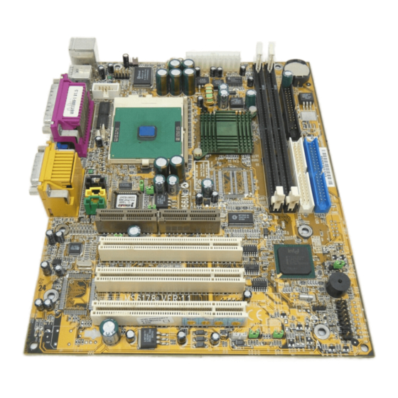
Page 104: Mainboard Layout
SDRAM Top: Midi/ Game Port Bottom: CD_IN Line-Out Line-In AUX_IN MODEM_IN CODEC PCI SLOT 1 JGS1 PCI SLOT 2 Aureal Vortex 8810 JGL1 JMDM1 (optional) SYSFAN PCI SLOT 3 (optional) JWOL1 JBAT1 J22 (Optional) JFP1 MS-6178 MICRO ATX WH5 Mainboard...
Need help?
Do you have a question about the MS-6178 and is the answer not in the manual?
Questions and answers