Advertisement
Quick Links
CHAPTER 1
INTRODUCTION
Chapter 1
INTRODUCTION
The Micro ATX IR2 mainboard is a high-performance personal computer
®
mainboard based on the AMD Athlon
processor. This mainboard provides
®
®
onboard Creative
ES1373 PCI technology in audio. The AMD Athlon
TM
processor is the newest microprocessor in the AMD K86
family of
microprocessors.
®
The mainboard uses the highly integrated AMD
751 system controller and
AMD 756 peripheral controller. The AMD-751 system controller features:
the S2k system interface supports a 100Mhz clock and double-data rate
(DDR) transfers, the 33MHz 32-bit bus interface supports up to three
masters, the 66MHz AGP 1.0 compliant interface supports 2x data transfer
mode, and High Speed memory designed to support a 100MHz SDRAM (PC-
100-compatible-DIMM) with serial presence detect(PSD). The AMD-756
peripheral bus controllers feature an integrated ISA bus controller, an
enhanced IDE controller with Ultra DMA-66 support, and a keyboard/mouse
controller.
The MS-6191 ATX IR2 mainboard is one of our system board to implement
the AMD-750 chipset (AMD-751 and AMD-756), which supports a single
®
Slot A for AMD Athlon
processor.
1-1
Advertisement

Related Manuals for MSI MS-6191 Micro ATX IR2


Summary of Contents for MSI MS-6191 Micro ATX IR2
- Page 1 CHAPTER 1 INTRODUCTION Chapter 1 INTRODUCTION The Micro ATX IR2 mainboard is a high-performance personal computer ® mainboard based on the AMD Athlon processor. This mainboard provides ® ® onboard Creative ES1373 PCI technology in audio. The AMD Athlon processor is the newest microprocessor in the AMD K86 family of microprocessors.
- Page 2 CHAPTER 1 INTRODUCTION 1.1 Mainboard Features l Slot A for AMD ® Athlon processor. l Support 500MHz, 550MHz, 600MHz, or higher processor Chipset l AMD ® Irongate chipset. (Northbridge) - 200MHz EV6 System Interface speed - 100MHz SDRAM - 1x/2x AGP - Status - Silicon currently in bring-up l AMD ®...
- Page 3 CHAPTER 1 INTRODUCTION On-Board IDE l An IDE controller on the AMD ® Viper chipset provides IDE HDD/ CD-ROM with PIOand Ultra DMA/66 operation modes. l Can connect up to four IDE devices. On-Board Peripherals l On-Board Peripherals include: - 1 floppy port supports 2 FDD with 360K, 720K, 1.2M, 1.44M and 2.88Mbytes.
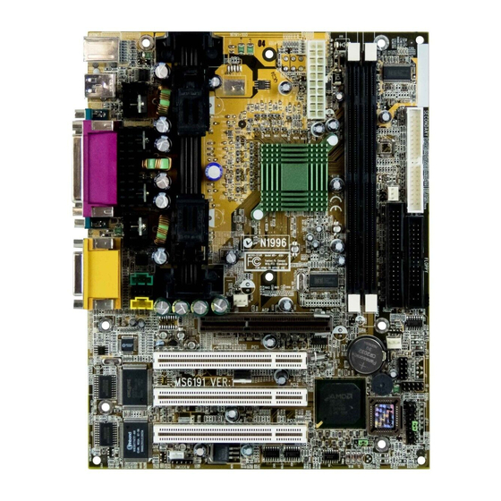
- Page 4 Top: LPT AMD-751 Bottom: COM A chipset COM B Top: MIDI/ Game Port Bottom: Audio Port AGP Slot BATT JSLP1 PCI SLOT 1 USB2 PCI SLOT 2 AMD-756 chipset PCI SLOT 3 JWOL JFP1 JBAT1 JMODEM MS-6191 Micro ATX IR2 Mainboard...
- Page 5 CHAPTER 2 HARDWARE INSTALLATION Chapter 2 HARDWARE INSTALLATION 2.1 Central Processing Unit: CPU 2.1-1 Processor Installation Procedure Step 1: Install the Retention Mechanism. Attach the Retention Mechanism to the Mainboard. Push the Plastic lock to secure the Retention Mechanism into the mainboard. Secure the processor by pulling up the Retention Insert the processor...
- Page 6 CHAPTER 2 HARDWARE INSTALLATION 2.1-2 CPU Core Speed Derivation Procedure The Mainboard can auto-detect the processor speed. Just insert the AMD Athlon processor into Slot A. CPU Clock 100MHz Core/Bus ratio then CPU core speed Host Clock x Core/Bus ratio 100MHz x 5 500MHz...
- Page 7 CHAPTER 2 HARDWARE INSTALLATION 2.1-4 Fan Power Connectors: J9, J12, & J6 These connectors support system cooling fan with + 12V. It supports three pin head connector. When connecting the wire to the connector, always take note that the red wire is the positive and should be connected to the +12V, the black wire is Ground and should be connected to GND.
- Page 8 CHAPTER 2 HARDWARE INSTALLATION 2.2 Clear CMOS Jumper: JBAT1 A battery must be used to retain the mainboard configuration in CMOS RAM. Short 1-2 pins of JBAT1 to store the CMOS data. JBAT1 Clear Data Keep Data Note: You can clear CMOS by shorting 2-3 pin, while the system is off. Then, return to 1-2 pin position.
- Page 9 CHAPTER 2 HARDWARE INSTALLATION 2.3 Memory Installation 2.3-1 Memory Bank Configuration The mainboard supports a maximum memory size of 512MB for SDRAM: It provides two 168-pin unbuffered DIMMs (Double In-Line Memory Module) sockets. It supports 8 MB to 256 Mbytes DIMM memory module.
- Page 10 CHAPTER 2 HARDWARE INSTALLATION 2.3-2 Memory Installation Procedures A. How to install a DIMM Module Single Sided DIMM Double Sided DIMM 1. The DIMM slot has 2 Notch Keys “VOLT and DRAM”, so the DIMM memory module can only fit in one direction. 2.
- Page 11 CHAPTER 2 HARDWARE INSTALLATION 2.3-3 Memory Population Rules 1. Supports only PC100 SDRAM DIMM. 2. To operate properly, at least one 168-pin DIMM module must be in- stalled. 3. This mainboard supports Table Free memory, so memory can be installed on DIMM1 or DIMM 2 in any order.
- Page 12 CHAPTER 2 HARDWARE INSTALLATION 2.4 Case Connector: JFP1 The Keylock, Power Switch, Reset Switch, Power LED, Speaker, and HDD LED are all connected to the JFP1 connector block. Keylock Buzzer Power LED (short Dual pin) Color Speaker Power Switch Reset Switch JFP1...
- Page 13 CHAPTER 2 HARDWARE INSTALLATION 2.4-1 Power Switch Connect to a 2-pin push button switch. This switch has the same feature with JRMS1. 2.4-2 Reset Switch Reset switch is used to reboot the system rather than turning the power ON/ OFF. Avoid rebooting while the HDD LED is lit. You can connect the Reset switch from the system case to this pin.
- Page 14 CHAPTER 2 HARDWARE INSTALLATION 2.5 Floppy Disk Connector: FDD The mainboard also provides a standard floppy disk connector FDD that supports 360K, 720K, 1.2M, 1.44M and 2.88M floppy disk types. This connector supports the provided floppy drive ribbon cables. 2-10...
- Page 15 CHAPTER 2 HARDWARE INSTALLATION 2.6 Hard Disk Connectors: IDE1 & IDE2 The mainboard has a 32-bit Enhanced PCI IDE and Ultra DMA/66 (ICH)/ Ultra DMA/33(ICH0) Controller that provides PIO mode 0~4, Bus Master, and Ultra DMA/33 function. It has two HDD connectors IDE1 (primary) and IDE2 (secondary).
- Page 16 CHAPTER 2 HARDWARE INSTALLATION 2.7 Power Supply 2.7-1 ATX 20-pin Power Connector: JPWR1 This connector supports the power button on-board. Using the ATX power supply, functions such as Modem Ring Wake-Up and Soft Power Off are supported by this mainboard. This power connector supports instant power on function which means that system will boot up instantly when the power connector is inserted on the board.
- Page 17 CHAPTER 2 HARDWARE INSTALLATION 2.8 IrDA Infrared Module Connector: IR The mainboard provides one infrared (IR) connector for IR modules. This connector is for optional wireless transmitting and receiving infrared module. You must configure the setting through the BIOS setup to use the IR function.
- Page 18 CHAPTER 2 HARDWARE INSTALLATION 2.9 Serial Port Connectors: COM A and COM B The mainboard provides two 9-pin male DIN connector for serial port COM A and COM B. These port are 16550A high speed communication port that send/receive 16 bytes FIFOs. You can attach a mouse or a modem cable directly into this connector.
- Page 19 CHAPTER 2 HARDWARE INSTALLATION 2.10 Parallel Port Connector: LPT1 The mainboard provides a 25 pin female centronic connector for LPT. A parallel port is a standard printer port that also supports Enhanced Parallel Port(EPP) and Extended capabilities Parallel Port(ECP). See connector and pin definition below: Parallel Port (25-pin Female) LPT 1...
- Page 20 CHAPTER 2 HARDWARE INSTALLATION 2.11 Mouse Connector: JKBMS1 ® The mainboard provides a standard PS/2 mouse mini DIN connector for ® ® attaching a PS/2 mouse. You can plug a PS/2 mouse directly into this connector. The connector location and pin definition are shown below: Pin5 Mouse Clock Pin6...
- Page 21 CHAPTER 2 HARDWARE INSTALLATION 2.13 USB Connectors The mainboard provides a UHCI(Universal Host Controller Interface) Universal Serial Bus root for attaching USB devices like: keyboard, mouse and other USB devices. You can plug the USB device directly to this connector. USB Port 2 1 2 3 4 USB Port 1...
- Page 22 CHAPTER 2 HARDWARE INSTALLATION 2.14 Joystick/Midi Connectors You can connect joystick or game pad to this connector. Joystick/MIDI 2.15 Audio Port Connectors Line Out is a connector for Speakers or Headphones. Line In is used for external CD player, Tape layer, or other audio devices. Mic is a connector for the microphones.
- Page 23 CHAPTER 2 HARDWARE INSTALLATION 2.16 USB Front Connector The mainboard provides a front Universal Serial Bus connector. This is an optional USB connector for Front Panel. USB2 2-19...
- Page 24 CHAPTER 2 HARDWARE INSTALLATION 2.17 Wake-Up on LAN Connector: JWOL The JWOL connector is for use with LAN add-on cards that supports Wake Up on LAN function. To use this function, you need to set the “Wake-Up on LAN” to enable at the BIOS Power Management Setup. JWOL SIGNAL 5VSB...
- Page 25 CHAPTER 2 HARDWARE INSTALLATION 2.18 Power Saving Switch Connector: JSLP1 Attach a power saving switch to JSLP1. When the switch is pressed, the system immediately goes into suspend mode. Press any key and the system wakes up. JSLP1 2-21...
- Page 26 CHAPTER 2 HARDWARE INSTALLATION 2.19 Modem Wake Up Connector: JMODEM The JMODEM connector is for use with Modem add-on card that supports the Modem Wake Up function. To use this function, you need to set the “Power On By Ring” to enable at the BIOS Power Management Setup. JMODEM SIGNAL MDM_WAKEUP...
- Page 27 CHAPTER 2 HARDWARE INSTALLATION 2.20 Modem-In: J16 The connector is for Modem with internal voice connector. SPK IN GND MIC OUT SPK_IN is connected to the Modem Speaker Out connector. MIC_OUT is connected to the Modem Microphone In connector. 2-23...
- Page 28 CHAPTER 2 HARDWARE INSTALLATION 2.21 CD-In Connector: J14 This connector is for CD-ROM Audio Connector. 2-24...
- Page 29 CHAPTER 2 HARDWARE INSTALLATION 2.22 Aux Line In Connector: J15 This connector is used for DVD Add on Card with Line In connector. 2-25...
- Page 30 ® Chapter 3 AWARD BIOS SETUP ® Award BIOS ROM has a built-in Setup program that allows users to modify the basic system configuration. This type of information is stored in battery-backed RAM (CMOS RAM), so that it retains the Setup information when the power is turned off.
- Page 31 ® Power on the computer and press <Del> immediately to allow you to enter Setup. The other way to enter Setup is to power on the computer. When the below message appears briefly at the bottom of the screen during the POST (Power On Self Test), press <Del>...
- Page 32 ® ® Once you enter Award BIOS CMOS Setup Utility, the Main Menu (Figure 1) will appear on the screen. The Main Menu allows you to select from twelve setup functions and two exit choices. Use arrow keys to select among the items and press <Enter>...
- Page 33 ® Advanced Chipset Features Use this menu to change the values in the chipset registers and optimize your system’s performance. Integrated Peripherals Use this menu to specify your settings for integrated peripherals. Power Management Setup Use this menu to specify your settings for power management. PnP/PCI Configurations This entry appears if your system supports PnP/PCI.
- Page 34 ® The items in Standard CMOS Setup Menu are divided into 10 catego- ries. Each category includes no, one or more than one setup items. Use the arrow keys to highlight the item and then use the <PgUp> or <PgDn> keys to select the value you want in each item.
- Page 35 ® Date The date format is <day><month> <date> <year>. Day of the week, from Sun to Sat, determined by BIOS. Read-only. month The month from Jan. through Dec. date The date from 1 to 31 can be keyed by numeric function keys.
- Page 36 ® If the controller of HDD interface is SCSI, the selection shall be “None”. If the controller of HDD interface is CD-ROM, the selection shall be “None”. Access Mode The settings are Auto, Normal, Large,LBA. Cylinder number of cylinders Head number of heads Precomp write precom...
- Page 37 ® CMOS Setup Utility - Copyright(C) 1984-1999 Award Software Advanced BIOS Features Virus Warning Disabled CPU Internal Cache Enabled Item Help External Cache Enabled Quick Power On Self Test Disabled First Boot device Floppy Menu Level > Second Boot device HDD-0 Third Boot device LS/Zip...
- Page 38 ® CPU Internal Cache The default value is Enabled. Enabled (default) Enable cache Disabled Disable cache Note: The internal cache is built in the processor. External Cache Choose Enabled or Disabled. This option enables the level 2 cache memory. Quick Power On Self Test This category speeds up Power On Self Test (POST) after you power on the computer.
- Page 39 ® Boot Up NumLock Status The default value is On. Keypad is numeric keys. Off(default) Keypad is arrow keys. Gate A20 Option Normal The A20 signal is controlled by keyboard controller or chipset hardware. Fast(default) The A20 signal is controlled by port 92 or chipset specific method.
- Page 40 ® OS Selection for DRAM > 64MB ® Allows OS2 to be used with > 64 MB of DRAM. Settings are Non- OS/2 (default) and OS2. Set to OS/2 if using more than 64MB and running ® OS/2 Video BIOS Shadow Determines whether video BIOS will be copied to RAM for faster execution.
- Page 41 ® The Advanced Chipset Features Setup option is used to change the values of the chipset registers. These registers control most of the system options in the computer. Choose the “ADVANCED CHIPSET FEATURES” from the Main Menu and the following screen will appear. CMOS Setup Utility - Copyright(C) 1984-1999 Award Software Advanced Chipset Features SDRAM Precharge Control...
- Page 42 ® SDRAM Precharge Control This items allows you to Enabled or Disabled SDRAM Precharge Control. System BIOS Cacheable Selecting Enabled allows caching of the system BIOS ROM at F0000h-FFFFFh, resulting in better system performance. However, if any program writes to this memory area, a system error may result. The settings are: Enabled and Disabled.
- Page 43 ® SDRAM PH Limit This item specify the number of consecutive Page-Hit requests to allow before choosing a non Page-Hit request. The settings are: 1/4/32/64 cycles. SDRAM Idle Limit This item specify the number of idel cycles to wait before precharging an idle bank.
- Page 44 ® CMOS Setup Utility - Copyright(C) 1984-1999 Award Software Integrated Peripherals IDE Read/Write Prefetch Disabled IDE Primary Master PIO Auto Item Help IDE Primary Slave PIO Auto IDE Secondary Master PIO Auto IDE Secondary Slave PIO Auto Menu Level > IDE Primary Master UDMA Auto IDE Primary Slave UDMA...
- Page 45 ® IDE Primary/Secondary Master/Slave PIO The four IDE PIO (Programmed Input/Output) fields let you set a PIO mode (0-4) for each of the four IDE devices that the onboard IDE interface supports. Modes 0 through 4 provide successively increased performance. In Auto mode, the system automatically determines the best mode for each device.
- Page 46 ® IDE HDD Block Mode Block mode is also called block transfer, multiple commands, or multiple sector read/write. If your IDE hard drive supports block mode (most new drives do), select Enabled for automatic detection of the optimal number of block read/writes per sector the drive can support. The settings are: Enabled, Disabled.
- Page 47 ® Onboard Parallel Port Disabled There is a built-in parallel port on the (3BCH/IRQ7)/ on-board Super I/O chipset that pro- (278H/IRQ5)/ vides Standard, ECP, and EPP features. (378H/IRQ7) It has the following options: Disable 3BCH/IRQ7 Line Printer port 0 278H/IRQ5 Line Printer port 2 378H/IRQ7 Line Printer port 1...
- Page 48 ® channels 3 or 1. The onboard parallel port is EPP Spec. compliant, so after the user chooses the onboard parallel port with the EPP function, the following message will be displayed on the screen: “EPP Mode Select.” At this time either EPP 1.7 spec.
- Page 49 ® The Power Management Setup allows you to configure you system to most effectively save energy while operating in a manner consistent with your own style of computer use. CMOS Setup Utility - Copyright(C) 1984-1999 Award Software Power Management Setup ACPI Function Enabled Item Help...
- Page 50 ® Power Management This category allows you to select the type (or degree) of power saving and is directly related to the following modes: Suspend Mode HDD Power Down There are three selections for Power Management, two of which have fixed mode settings.
- Page 51 ® HDD Power Down When enabled and after the set time of system inactivity, the hard disk drive will be powered down while all other devices remain active. The settings are: 1/2/3/4/5/6/7/8/9/10/11/12/13/14/15Min and Disabled. HDD Down In Suspend When enabled, the hard disk drive will be powered down with the other device during suspend mode.
- Page 52 ® Reload Global Timer events are I/O events whose occurrence can prevent the system from entering a power saving mode or can awaken the system from such a mode. In effect, the system remains alert for anything which occurs to a device which is configured as Enabled , even when the system is in a power down mode.
- Page 53 ® This section describes configuring the PCI bus system. PCI, or Personal Computer Interconnect, is a system which allows I/O devices to operate at speeds nearing the speed the CPU itself uses when communicating with its own special components. This section covers some very technical items and it is strongly recommended that only experienced users should make any changes to the default settings.
- Page 54 ® Reset Configuration Data Normally, you leave this field Disabled. Select Enabled to reset Extended System Configuration Data (ESCD) when you exit Setup if you have installed a new add-on and the system reconfiguration has caused such a serious conflict that the operating system can not boot. The settings are: Enabled and Disabled.
- Page 55 ® This section is for setting CPU Frequency/Voltage Control. CMOS Setup Utility - Copyright(C) 1984-1999 Award Software Frequency/Voltage Control Auto Detect DIMM/PCI Clk Enabled CPU Clock/Spread Spectrum Default Item Help Menu Level > ↑ ↓ → ← Move Enter:Select +/-/PU/PD:Value F10:Save ESC:Exit F1:General Help F5:Previous Values F6:Fail-safe defaults F7:Optimized Defaults Auto Detect DIMM/PCI CLK This item allows you to enable/disable auto detect DIMM/PCI Clock.
- Page 56 ® Load Fail-Safe Defaults When you press <Enter> on this item, you get a confirmation dialog box with a message similar to: Load Fail-Safe Defaults (Y/N) ? N Pressing ‘Y’ loads the BIOS default values for the most stable, minimal- performance system operations.
- Page 57 ® You can set either supervisor or user password, or both of them. The differences are: Supervisor password : can enter and change the options of the setup menus. User password Can only enter but do not have the right to change the options of the setup menus.
- Page 58 ® You determine when the password is required within the BIOS Features Setup Menu and its Security option. If the Security option is set to “Sys- tem”, the password will be required both at boot and at entry to Setup. If set to “Setup”, prompting only occurs when trying to enter Setup.
- Page 59 ® Chapter 3 ® BIOS USER’S GUIDE The system configuration information and chipset register information is stored in the CMOS RAM. This information is retained by a battery when the power is off. Enter the BIOS setup (if needed) to modify this information. The following pages will describe how to enter BIOS setup, and all about options.
- Page 60 ® 3.1 Enter BIOS Setup ® Enter the AMI setup Program’s Main Menu as follows: 1. Turn on or reboot the system. The following screen appears with a series of diagnostic check. AMIBIOS (C) 1999 American Megatrends Inc. A6191 VXXX XXXXXX Hit <DEL>...
- Page 61 ® AMIBIOS HIFLEX SETUP UTILITIES - VERSION 1.22 (C) 1999 American Megatrends, Inc. All Rights Reserved Standard CMOS Setup Advanced CMOS Setup Advanced Chipset Setup Power Management Setup PCI/Plug and Play Setup Peripheral Setup Auto-Detect Hard Disks Change User Password Change Supervisor Password Auto Configuration with Optimal Settings Auto Configuration with Fail Safe Settings...
- Page 62 ® 3.2 Standard CMOS Setup 1. Press <ENTER> on “Standard CMOS Setup” of the main menu screen . AMIBIOS SETUP - STANDARD CMOS SETUP (C)1999 American Megatrends,Inc.All Rights Reserved Date (mm/dd/yyyy): Fri Oct 29, 1999 Time (hh/mm/ss): 17:09:25 Floppy Drive A: 1.44 MB 3 1/2 Floppy Drive B: Not Installed...
- Page 63 ® 3.3 Advanced CMOS Setup 1. Press <ENTER> on “Advanced CMOS Setup” of the main menu AMIBIOS SETUP - ADVANCED CMOS SETUP (C) 1999 American Megatrends, Inc. All Rights Reserved Quick Boot Enabled Available Options: 1st Boot Device Floppy Disabled 2nd Boot Device CD-ROM Enabled...
- Page 64 ® Description of the item on screen follows: Quick Boot ® Set this option to Enabled to permit AMI BIOS to boot within 5 seconds. This option replaces the old ABOVE 1 MB Memory Test option. The Optimal default setting is Enabled. The Fail-Safe default setting is Disabled.
- Page 65 ® S.M.A.R.T. for Hard Disks This option sets the SMART Function for the hard disk. The hard disk need to have SMART function for this feature to work. Boot up Num Lock ® When this option is set to Off, AMI BIOS turns off the Num Lock key when the system is powered on.
- Page 66 ® ® Boot To OS/2 > 64MB Set this option to Enabled to permit the BIOS to run properly, if ® OS/2 is to be used with > 64MB of DRAM. The settings are Enabled or Disabled. The Optimal and Fail-safe default settings are Disabled. Internal Cache This option Enabled or Disabled the Internal Cache.
- Page 67 ® 3.4 Advanced Chipset Setup 1. Press <ENTER> on “Advanced Chipset Setup” of the main menu screen. AMIBIOS SETUP - ADVANCED CHIPSET SETUP (C) 1999 American Megatrends, Inc. All Rights Reserved ******** SDRAM Timing ******** Available Options: Configure SDRAM Timing by SPD Disabled Disabled SDRAM PH Limit...
- Page 68 ® Description of the item on screen follows: Configure SDRAM Timing By SPD Choose Enabled, will automatically configure the DRAM Timing depending on the “DRAM Speed” selection. Choose Disabled, to customize the setup. SDRAM PH Limit This item specify the number of consecutive Page-Hit requests to allow before choosing a non Page-Hit request.
- Page 69 ® DRAM Integrity Mode Set this option to Enabled or Disabled the DRAM integrity mode. The Optional and Fail-Safe default settings are Disabled. Memory Hole This option allows the end user to specify the location of a memory hole. The cycle matching the selected memory hole will be passed to the ISA bus.
- Page 70 ® Spread Spectrum This item allows you to seclect the clock generator Spread Spec- trum function. the default is Enabled. This item should always be set to Disabled, if you overclock the processor. If you set to Enabled, it will work better for EMI test.
- Page 71 ® 3.5 Power Management Setup 1. Press <ENTER> on “Power Management Setup” of the main menu screen. AMIBIOS SETUP - POWER MANAGEMENT SETUP (C) 1999 American Megatrends, Inc. All Rights Reserved Available Options: ACPI Aware O/S Power Management/APM Enabled Disabled Enabled Green PC Monitor Power State Suspend...
- Page 72 ® Description of the item on screen follows: ACPI Aware O/S This option sets the ACPI Power Management to be active or not. The settings are yes or no. Power Management/APM Set this option to Enabled to enable the chipset’s power manage- ment features and APM(Advanced Power Management).
- Page 73 ® Modem Use IO Port This indicates which I/O port will be used by the Modem (if there is a modem installed) Modem Use IRQ This indicates which IRQ number will be used by the Modem (if there is a modem installed). Power Button Function During Suspend, if you push the switch once, the system goes into suspend mode and if you push it more than 4 seconds, the system will...
- Page 74 ® LAN Resume from Soft-Off During Disabled, the system will ignore any incoming signal from the LAN network card. During Enabled, the system will boot up if there’s an incoming signal from the LAN network card. Note: If you have change the setting, you must let the system boot up until it goes to the operating system.
- Page 75 ® 3.6 PCI/Plug and Play Setup 1. Press <ENTER> on “PCI/Plug and Play Setup” of the main menu screen. AMIBIOS SETUP - PCI/PLUG AND PLAY SETUP (C) 1999 American Megatrends, Inc. All Rights Reserved Available Options: Plug and Play Aware O/S Enabled Clear NVRAM PCI Latency Timer (PCI Clocks)
- Page 76 ® Description of the item on screen follows: Plug and Play Aware O/S Set this option to Yes if the operating system in this computer is aware of and follows the Plug and Play specification. Currently, only ® Windows 95 is PnP-aware. The settings are Yes or No. The Optimal and Fail-Safe default settings No.
- Page 77 ® Offboard PCI IDE Card This option specifies if an offboard PCI IDE controller adapter card is installed in the computer. You must specify the PCI expansion slot on the mainboard where the offboard PCI IDE controller is installed. If an offboard PCI IDE controller is used, the onboard IDE controller is automatically ®...
- Page 78 ® IRQ3/IRQ4/IRQ5/RQ7/IRQ9/IRQ10/IRQ11/IRQ14/IRQ15 These options specify the bus that the specified IRQ line is used on. These options allow you to reserve IRQs for legacy ISA adapter cards. ® These options determine if AMI BIOS should remove an IRQ from the pool of available IRQs passed to devices that are configurable by the system BIOS.
- Page 79 ® 3.7 Peripheral Setup 1. Press <ENTER> on “Peripheral Setup” of the main menu screen. AMIBIOS SETUP - PERIPHERAL SETUP (C) 1999 American Megatrends, Inc. All Rights Reserved Available Options: Onboard FDC Auto Auto Onboard Serial Port A 3F8h/COM1 Disabled Onboard Serial Port B 2F8h/COM2 Enabled...
- Page 80 ® Description of the item on screen follows: Onboard FDC Choose Auto, for the BIOS to automatically detect the device If the ISA add-on card has Onboard FDC to be set at Disabled FDC exist Enabled none FDC exist Choose Enabled, Enabling onboard FDC. Choose Disabled, Disabling onboard FDC.
- Page 81 ® IR Port Support/IR Mode Select/IR IRQ Select/IR DMA Select This items allows the user to determine which InfraRed (IR) func- tion of the onboard I/O chip. Onboard Parallel Port Choose Auto, the BIOS automatically assigned onboard parallel port to the available parallel port or disabled. If the ISA add-on card has Onboard parallel port to be set as LPT1...
- Page 82 ® Parallel Port IRQ If the onboard parallel mode is not on auto mode, the user can select the interrupt line for onboard parallel port. We suggest that the user select the interrupt for the onboard parallel port as shown below: Parallel Port IRQ Onboard parallel port set at LPT1(378H)
- Page 83 ® 3.8 Auto-Detect Hard Disks You can use this utility to automatically detect the characteristics of most hard drives. AMIBIOS SETUP - STANDARD CMOS SETUP (C)1999 American Megatrends,Inc.All Rights Reserved Date (mm/dd/yyyy): Fri Oct 29, 1999 Time (hh/mm/ss): 17:09:25 Floppy Drive A: 1.44 MB 3 1/2 Floppy Drive B: Not Installed...
- Page 84 ® 3.9 Range User/Supervisor Password This Main Menu item lets you configure the system so that a password is required each time the system boots or an attempt is made to enter the Setup program. Supervisor Password allows you to change all CMOS settings but the User Password setting doesn’t have this function.
- Page 85 Chapter 4 CREATIVE AUDIO DRIVER ® The Creative ES1373 digital controller provides the next generation of audio performance to the PC market. 1.1 Features SoundScape WaveTable Synthesizer. Full DOS Game Compatibility. PCI Bus Master for fast DMA. Fully Compliant with PC97 Power Management Specification. 1.2 System Requirements This section describes system requirements for the Audio Driver installation and Usage.
- Page 86 Insert the CD-title into your CD-ROM drive. This CD will auto-run. This will display installation for VGA driver and sound driver. Just click the button for automatic installation for audio driver. ® 2.1 Windows 95/98/NT 4.0 ® If you start Windows 95/98/NT 4.0, this will automatically detect this hardware onboard “PCI Multimedia Audio Device”...
Need help?
Do you have a question about the MS-6191 Micro ATX IR2 and is the answer not in the manual?
Questions and answers