
Related Manuals for KonNad C2000-A2-SDD8020-DD3


Summary of Contents for KonNad C2000-A2-SDD8020-DD3
- Page 1 Last updated: 2020-1-10 C2000-A2-SDD8020-DD3 User Manual Ethernet ⇋ 8DI + 2DO Dry/Wet contact Remote I/O Module — Ethernet Digital I/O Module SinoCon Co., Ltd.
-
Page 2: Table Of Contents
C2000-A2-SDD8020-DD3 User Manual Catalog Catalog 1. Getting Started 1.1. Preparation Before Use 1.2. Wiring 1.3. Software Installation & Device Debugging 1.3.1. Software Installation 1.3.2. Device Debug 2. Hardware Description 2.1. Specifications 2.2. Apprearance 2.3. Indicators 2.4. Port Description 2.5. Product Dimensions 2.6. - Page 3 Copyright Notice ©2000 - 2020 SinoCon Co., Ltd. All Rights Reserved. Trademarks The KonNaD logo is a registered trademark of SinoCon Co., Ltd. All other trademarks or registered marks in this manual belong to their respective manufacturers. Disclaimer This document only provides information about KonNaD products. No license to any intellectual property rights is granted by this document, including any intellectual property licenses, expressed or implied, or by any means.
-
Page 4: Getting Started
C2000-A2-SDD8020-DD3 User Manual 1. Getting Started 1.1. Preparation Before Use You will need the following hardware and software to use the C2000-A2-SDD8020-DD3. • C2000-A2-SDD8020-DD3 module • A power source that provides 9 to 27 VDC, and several wires • A PC running a Windows 7 or later versions, and an Ethernet cable •... -
Page 5: Software Installation & Device Debugging
1.3. Software Installation & Device Debugging 1.3.1. Software Installation Download the software on URL: https://www.sinoconsys.com/en/download/?file=sdk. Unzip the folder and run KonNaD.Setup.exe as administrator. The setup wizard will pop up to direct you to complete the installation. 1.3.2. Device Debug Search Devices Select Search for Ethernet devices and Click Search to find all devices in the LAN. - Page 6 C2000-A2-SDD8020-DD3 User Manual • Check whether to install and run as administrator ; • Check whether the package (before decompression) is locked. You can resolve it by this method: Right- click the package -> Click "Properties" -> Go to the "General" tab -> Click on "Unlock file" -> Click OK. Then Unzip and Reinstall;...
- Page 7 C2000-A2-SDD8020-DD3 User Manual Refer to Software Tools for more detailed information. Refer to Registers for information on "Secondary Development". SinoCon Co., Ltd. www.sinoconsys.com 7 / 33...
-
Page 8: Hardware Description
C2000-A2-SDD8020-DD3 User Manual 2. Hardware Description 2.1. Specifications Classification Parameter Specification Digital Input DI Channels DI Connector Terminal block Input Type Dry contact: Logic 0, short to GND; Logic 1, open; Wet contact: Logic 0, 0~1VDC; Logic 1, 3~30VDC DI Mode Logic level &... - Page 9 C2000-A2-SDD8020-DD3 User Manual Classification Parameter Specification Cascade RS485 cascade connection Connection/Transparent Transmission Power Power Connector Terminal block Input Voltage 9~27VDC Current 200mA @ 12VDC Physical Dimensions 75*105*30mm Characteristics Installation Din-rail or wall Environmental Operating Temperature -40℃ ~ 85℃ Limits Storage Temperature -60℃...
-
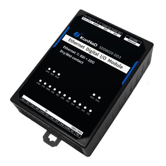
Page 10: Apprearance
C2000-A2-SDD8020-DD3 User Manual 2.2. Apprearance SinoCon Co., Ltd. www.sinoconsys.com 10 / 33... -
Page 11: Indicators
C2000-A2-SDD8020-DD3 User Manual 2.3. Indicators Classification Indicator Description Meaning Digital Input Digital input Steady on:Short to GND or input voltage more than indicators (dry/wet the threshold voltage contact) Off:Open or input voltage less than the threshold voltage Digital Digital input Steady on:On... -
Page 12: Port Description
C2000-A2-SDD8020-DD3 User Manual 2.4. Port Description Recommended Classification Port Description wiring Digital Input Digital input RVV 2*0.5 Wet contact input common RVV 2*0.5 Dry contact input common RVV 2*0.5 Digital Output Digital output normally open RVV 2*1.0 Digital output common RVV 2*1.0... -
Page 13: Product Dimensions
C2000-A2-SDD8020-DD3 User Manual 2.5. Product Dimensions unit: mm(inch) 2.6. Installation Method SinoCon Co., Ltd. www.sinoconsys.com 13 / 33... -
Page 14: Product Features
C2000-A2-SDD8020-DD3 User Manual 3. Product Features 3.1. DI Data Acquisition 3.1.1. DI Type Dry contact: Short DI and GND, the point value is 1; otherwise the point value is 0. Wet contact: When the input voltage (i.e. 3-30VDC) between DI and COM more than the threshold voltage, the point value is 1;... -
Page 15: Filter Parameters
C2000-A2-SDD8020-DD3 User Manual it can be counted from the initial value to the maximum value of 65535, and then it can be re-counted from 0. 3.3.2. Filter Parameters The DI signal must be kept for several sampling periods before it can be confirmed. The default value is 0x6, which means that 6 sample periods are required to be confirmed. -
Page 16: Software Tools
C2000-A2-SDD8020-DD3 User Manual 4. Software Tools 4.1. Main Screen The main screen displays the results of a broadcast search for the device. Main Screen 1. Set: Set the device parameters 2. Remote Set: For Ethernet type devices, when the device is in the LAN but crosses multiple routers and cannot be searched, the device parameters can be modified through Remote Set. -
Page 17: Use Software
C2000-A2-SDD8020-DD3 User Manual 6. Search for Ethernet devices: Used to search Ethernet type devices 7. Search for serial devices: Used to search serial port devices 8. Listening settings: Used to connect the device in client mode to the software tool. - Page 18 C2000-A2-SDD8020-DD3 User Manual · Obtain IP automatically: If you select it, when the DI detects the change of the connected switch, it will immediately upload it to the paired device with which the connection is established. · Auto upload data: If you select it, the DHCP server will automatically assign an IP address to the device, but you still need to manually set the gateway.
-
Page 19: View Device Status
C2000-A2-SDD8020-DD3 User Manual The "cascade connection" refers to the RS485 port of the device connected to our RS485 IO devices, which originally used Modbus RTU for communication. After cascading, the host computer can read the data of these cascaded RS485 IO devices through Modbus TCP. Up to 16 RS485 IO devices can be cascaded. When the host computer uses Modbus TCP to read the data of cascaded devices, to distinguish different 485 devices, it is necessary to map the 485 address of the device to the unit ID in Modbus TCP protocol. -
Page 20: Control Device Status
C2000-A2-SDD8020-DD3 User Manual 4.2.3. Control Device Status "DO Mode" can be set to "Level mode" or "Pulse mode", the software can change the digital output state of the device by changing the point value. · DO Mode - Level mode: When DO1 value is 1, the DO1 indicator is on; otherwise, it will be off. -
Page 21: Remote Settings
C2000-A2-SDD8020-DD3 User Manual 4.2.4. Remote Settings When the IP address of the device is configured in the LAN, but the device spans multiple routes and cannot be searched, the device parameters can be modified through Remote Set . Click Remote Set in the upper-left corner of the software, the pop-up dialog box to fill in the device IP address, the port 21678 is the default, you can configure the device parameters. -
Page 22: Protocol
C2000-A2-SDD8020-DD3 User Manual 5. Protocol The device uses the standard Modbus TCP protocol. If you have any questions about the protocol, you can refer to the relevant Modbus documentation or consult with our customer service. 5.1. Registers Start Number Parameter... - Page 23 C2000-A2-SDD8020-DD3 User Manual 40114 Reserved field Read as 0, write invalid 0x03,0x06,0x10 40115 Server IP or Default 10.1.2.132 For 0x03,0x06,0x10 domain name Client mode Save as a string 40147 Server port Default 9876, range from 0 0x03,0x06,0x10 to 65535 For Client mode...
- Page 24 C2000-A2-SDD8020-DD3 User Manual DO1 ~ DO2 0: OFF, 1: ON 0x01,0x05,0x0F status DO1 ~ DO2 0: OFF, 1: ON 0x01,0x05,0x0F power-on state 10200 DI1 ~ DI8 0: OFF, 1: ON 0x02 value 40300 DI1 ~ DI8 0: no valid positive pulse 0x03,0x06,0x10...
-
Page 25: Examples
C2000-A2-SDD8020-DD3 User Manual 40348 DI1 ~ DI8 0: manual zeroing 1: 0x03,0x06,0x10 automatic automatic zeroing zeroing 40349 DO1 ~ DO2 0: Level mode 1: Pulse 0x03,0x06,0x10 mode mode Other values are invalid 40351 DO1 ~ DO2 The minimum value is 50, 0x03,0x06,0x10... -
Page 26: Read Do Status (0X01)
C2000-A2-SDD8020-DD3 User Manual 0000 Protocol ID 2 Bytes, 0000 = Modbus protocol 0004 Length Field 2 Bytes, number of following bytes Unit ID 1 Byte, FF = Master device Function Code 1 Byte, 02 = Read Data Length 1 Byte, Data Length Data 1 Byte, Binary of 0xFF is "1111 1111", 1 is closed, 0 is open... -
Page 27: Write Do Status (0X0F)
C2000-A2-SDD8020-DD3 User Manual Function 1 Byte, 01 = Read Code Data Length 1 Byte, Data Length Data 1 Byte, Binary of 0x01 is "0000 0001" (1 bit indicates 1 channel), 1 is closed, 0 is open 5.2.3. Write DO Status (0x0F) You can write 0 or 1 to the register, the value 0 indicates COM and NO are open, and the value 1 indicates COM and NO are close. -
Page 28: Write Single Do Status (0X05)
C2000-A2-SDD8020-DD3 User Manual Unit ID 1 Byte, 0xFF = Master device Function Code 1 Byte, 0F = Write 0064 Starting Address 2 Bytes, address of the first register 0002 Quantity of Registers 2 Bytes, the number of required registers 5.2.4. Write Single DO Status (0x05) You can write 0000 or FF00 to the register, the value 0000 indicates COM and NO are open, and the value FF00 indicates COM and NO are close. -
Page 29: Di Data Auto-Upload
1 Byte, Binary of 0x01 is "0000 0001" (1 bit indicates 1 channel), 1 is closed, 0 is open 5.2.6. Read DI Status of Cascading Device (0x02) Acquire 4-channel DI of cascaded device C2000-A2-SDD4040-AD1 with address 01 connected to the device (C2000-A2-SDD8020-DD3), the command is as follows: 000100000006010200C80004 Command Field... -
Page 30: Write Do Status Of Cascading Device (0X0F)
2 Bytes, the number of required registers 5.2.7. Write DO Status of Cascading Device (0x0F) Control 4-channel DO of cascaded device C2000-A2-SDD4040-AD1 with address 01 connected to the device (C2000-A2-SDD8020-DD3), Close DO1-DO2, and open DO3-DO4, the command is as follows: 0x000100000008010F006400040103 Command... - Page 31 C2000-A2-SDD8020-DD3 User Manual Function Code 1 Byte, 0F = Write 0064 Starting Address 2 Bytes, address of the first register 0004 Quantity of 2 Bytes, the number of required registers Registers Data Length 1 Byte, Data Length Data 1 Byte, Binary of 0x03 is "0011" (1 bit indicates 1 channel), 1 is closed, 0 is...
- Page 32 C2000-A2-SDD8020-DD3 User Manual 6. Package Contents Contents Device (contain mounting kit) * 1 Terminal block * 1 set Installation guide card * 1 SinoCon Co., Ltd. www.sinoconsys.com 32 / 33...
-
Page 33: Warranty Policy
C2000-A2-SDD8020-DD3 User Manual 7. Warranty Policy In the normal use of the products you purchased, free warranty service will be provided from the date of purchase whenever the quality problems caused by raw materials or production process are concerned. However, due to the user's failure to install, disassemble or improperly use the product according to the requirements of this product manual, the company provides maintenance services, but charges appropriate maintenance fees.
Need help?
Do you have a question about the C2000-A2-SDD8020-DD3 and is the answer not in the manual?
Questions and answers