Table of Contents
Advertisement
Quick Links
Advertisement
Table of Contents

Subscribe to Our Youtube Channel
Related Manuals for Dell EMC 6WDJR


Summary of Contents for Dell EMC 6WDJR
- Page 1 Questo manuale d’istruzione è fornito da trovaprezzi.it. Scopri tutte le offerte per Dell PowerEdge R340 6WDJR o cerca il tuo prodotto tra le migliori offerte di Server Dell EMC PowerEdge R340 Installation and Service Manual Regulatory Model: E58S Series Regulatory Type: E58S001...
- Page 2 Notes, cautions, and warnings NOTE: A NOTE indicates important information that helps you make better use of your product. CAUTION: A CAUTION indicates either potential damage to hardware or loss of data and tells you how to avoid the problem. WARNING: A WARNING indicates a potential for property damage, personal injury, or death.
-
Page 3: Table Of Contents
Contents 1 About this document............................7 2 Dell EMC PowerEdge R340 system overview....................8 Front view of the system..............................8 Control panels................................9 Rear view of the system..............................10 Inside the system................................11 Locating the information tag of your system......................... 11 System Information label..............................12 PowerEdge R340 –... - Page 4 Front bezel..................................42 Removing the optional front bezel...........................42 Installing the optional front bezel..........................43 System cover..................................43 Removing the system cover............................. 43 Installing the system cover............................44 Air shroud..................................45 Removing the air shroud............................45 Installing the air shroud............................. 46 Cooling fans..................................47 Removing the cooling fan blank..........................
- Page 5 Removing the optical drive............................75 Installing the optional optical drive........................... 76 Processor and heat sink..............................77 Removing the heat sink............................. 77 Removing the processor............................78 Installing the processor..............................79 Installing the heat sink...............................80 Optional IDSDM or vFlash module..........................81 Removing the optional IDSDM or vFlash card......................81 Installing optional IDSDM or vFlash card.........................82 Removing the MicroSD card............................
- Page 6 9 Getting help............................... 126 Recycling or End-of-Life service information......................126 Contacting Dell................................126 Accessing system information by using QRL......................126 Quick Resource Locator for Dell EMC PowerEdge R340 system..............127 Receiving automated support with SupportAssist ....................127 10 Documentation resources......................... 128 Contents...
-
Page 7: About This Document
About this document This document provides an overview about the system, information about installing and replacing components, technical specifications, diagnostic tools, and guidelines to be followed while installing certain components. About this document... -
Page 8: Dell Emc Poweredge R340 System Overview
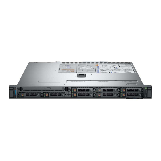
Dell EMC PowerEdge R340 system overview The Dell EMC PowerEdge R340 system is a 1U server that supports: • One Intel Xeon Scalable processor • Four DIMM slots • Two AC power supply units • Up to eight 2.5-inch or four 3.5-inch SAS, SATA drives... -
Page 9: Control Panels
Right control panel Information tag Drives (4) For more information about the ports, see the Technical Specifications section. Control panels Left control panel Figure 3. Left control panel view System health and system ID indicator Dell EMC PowerEdge R340 system overview... -
Page 10: Rear View Of The System
System identification button System status indicator cable port (CMA) USB 3.0 port (2) iDRAC9 dedicated network port VGA port NOTE: For more information about the ports and connectors, see the Ports and connectors specifications section. Dell EMC PowerEdge R340 system overview... -
Page 11: Inside The System
Tag by pulling out the information tag located on the front of the system. Alternatively, the information may be on the Mini Enterprise Service Tag (MEST) label on the chassis, on the rear of the system. This information is used by Dell to route support calls to the appropriate personnel. Dell EMC PowerEdge R340 system overview... -
Page 12: System Information Label
OpenManage Mobile (OMM) label iDRAC MAC address and iDRAC secure password label Service Tag, Express Service Code, QRL label System Information label PowerEdge R340 – System Information Label Figure 8. Front and rear view configuration Dell EMC PowerEdge R340 system overview... - Page 13 Figure 9. Jumper settings Figure 10. Memory information Dell EMC PowerEdge R340 system overview...
- Page 14 Figure 11. System information Dell EMC PowerEdge R340 system overview...
- Page 15 Figure 12. Electrical overview Dell EMC PowerEdge R340 system overview...
-
Page 16: Initial System Setup And Configuration
Initial system setup and configuration Setting up your system Perform the following steps to set up your system: Unpack the system. Install the system into the rack. For more information about installing the system into the rack, see the Rail Installation Guide at Dell.com/poweredgemanuals. -
Page 17: Log In To Idrac
Ensure that you change the default user name and password after setting up the iDRAC IP address. NOTE: The Intel Quick Assist Technology (QAT) on the Dell EMC PowerEdge R340 is supported with chipset integration and is enabled through an optional license. The license files are enabled on the sleds through iDRAC. -
Page 18: Downloading Drivers And Firmware
Using iDRAC virtual media Dell.com/idracmanuals Downloading drivers and firmware Dell EMC recommends that you download and install the latest BIOS, drivers, and systems management firmware on your system. Prerequisite Ensure that you clear the web browser cache before downloading the drivers and firmware. -
Page 19: Pre-Operating System Management Applications
Pre-operating system management applications You can manage basic settings and features of a system without booting to the operating system by using the system firmware. Topics: • Options to manage the pre-operating system applications • System Setup • Dell Lifecycle Controller •... -
Page 20: System Setup Details
System Setup details The System Setup Main Menu screen details are explained as follows: Option Description System BIOS Enables you to configure BIOS settings. iDRAC Settings Enables you to configure the iDRAC settings. The iDRAC settings utility is an interface to set up and configure the iDRAC parameters by using UEFI (Unified Extensible Firmware Interface). - Page 21 Option Description Legacy network settings are managed from the Device Settings menu. Integrated Devices Specifies options to manage integrated device controllers and ports, specifies related features and options. Serial Specifies options to manage the serial ports, its related features and options. Communication System Profile Specifies options to change the processor power management settings, memory frequency.
- Page 22 Option Description System Specifies the contact information of the system manufacturer. Manufacturer Contact Information System CPLD Specifies the current version of the system complex programmable logic device (CPLD) firmware. Version UEFI Compliance Specifies the UEFI compliance level of the system firmware. Version Memory Settings You can use the Memory Settings screen to view all the memory settings and enable or disable specific memory functions, such as system...
- Page 23 Option Description Current State of Specifies the current state of the memory operating mode. Memory Operating Mode Processor Settings You can use the Processor Settings screen to view the processor settings, and perform specific functions such as enabling virtualization technology, hardware prefetcher, and logical processor idling. Viewing Processor Settings To view the Processor Settings screen, perform the following steps: Power on, or restart your system.
- Page 24 Option Description Processor 1 The following settings are displayed for each processor installed in the system: Option Description Family-Model- Specifies the family, model, and stepping of the processor as defined by Intel. Stepping Brand Specifies the brand name. Level 2 Cache Specifies the total L2 cache.
- Page 25 Option Description Option Description Drive Type Specifies the type of drive attached to the SATA port. Capacity Specifies the total capacity of the hard drive. This field is undefined for removable media devices such as optical drives. Port B Sets the drive type of the selected device. When the Embedded SATA setting is AHCI Mode, BIOS support is always enabled.
- Page 26 Option Description Option Description Model Specifies the drive model of the selected device. Drive Type Specifies the type of drive attached to the SATA port. Capacity Specifies the total capacity of the hard drive. This field is undefined for removable media devices such as optical drives.
- Page 27 Option Description Hard-Disk Failover Specifies the drive that is booted in the event of a drive failure. The devices are selected in the Hard-Disk Drive Sequence on the Boot Option Setting menu. When this option is set to Disabled, only the first drive in the list is attempted to boot.
- Page 28 UEFI iSCSI Settings You can use the iSCSI Settings screen to modify iSCSI device settings. The iSCSI Settings option is available only in the UEFI boot mode. BIOS does not control network settings in the BIOS boot mode. For the BIOS boot mode, the option ROM of the network controller handles the network settings.
- Page 29 On the System BIOS screen, click Integrated Devices. Integrated Devices details The Integrated Devices screen details are explained as follows: Option Description User Accessible Configures the user accessible USB ports. Selecting Only Back Ports On disables the front USB ports; selecting USB Ports All Ports Off disables all front and back USB ports;...
- Page 30 Option Description Table 3. Slot Disablement Option Description Enables or disables or only the boot driver is disabled Slot 1 for the PCIe slot 1. This option is set to Enabled by default. Enables or disables or only the boot driver is disabled Slot 2 for the PCIe slot 2.
- Page 31 Option Description NOTE: Only Serial Device 2 can be used for Serial Over LAN (SOL). To use console redirection by SOL, configure the same port address for console redirection and the serial device. NOTE: Every time the system boots, the BIOS syncs the serial MUX setting saved in iDRAC. The serial MUX setting can independently be changed in iDRAC.
- Page 32 Option Description C States Enables or disables the processor to operate in all available power states. This option is set to Enabled by default. Memory Refresh Sets the memory refresh rate to either 1x or 2x. This option is set to 1x by default. Rate Uncore Frequency Enables you to select the Processor Uncore Frequency option.
- Page 33 Option Description System Password Sets the system password. This option is set to Enabled by default and is read-only if the password jumper is not installed in the system. Setup Password Sets the setup password. This option is read-only if the password jumper is not installed in the system. Password Status Locks the system password.
- Page 34 Option Description Secure Boot Policy When Secure Boot policy is set to Standard, the BIOS uses the system manufacturer’s key and certificates to authenticate pre-boot images. When Secure Boot policy is set to Custom, the BIOS uses the user-defined key and certificates.
- Page 35 Use the following guidelines to assign the system password: • A password can have up to 32 characters. • The password can contain the numbers 0 through 9. • Only the following special characters are allowed: space, (”), (+), (,), (-), (.), (/), (;), ([), (\), (]), (`). A message prompts you to reenter the system password.
- Page 36 Operating with setup password enabled If Setup Password is set to Enabled, type the correct setup password before modifying the system setup options. If you do not type the correct password in three attempts, the system displays the following message: Invalid Password! Number of unsuccessful password attempts: <x>...
- Page 37 Option Description NOTE: RAID configurations and NVMe cards not are included as BIOS does not have the ability to distinguish between individual drives in those configurations. Redundant OS NOTE: This option is disabled if Redundant OS Location is set to None. State When set to Visible, the backup disk is visible to the boot list and OS.
-
Page 38: Idrac Settings Utility
Option Description Load Legacy Video Enables you to determine whether the system BIOS loads the legacy video (INT 10H) option ROM from the video Option ROM controller. Selecting Enabled in the operating system does not support UEFI video output standards. This field is available only for UEFI boot mode. -
Page 39: Boot Manager
Boot Manager The Boot Manager screen enables you to select boot options and diagnostic utilities. Viewing Boot Manager About this task To enter Boot Manager: Steps Power on, or restart your system. Press F11 when you see the following message: F11 = Boot Manager If your operating system begins to load before you press F11, allow the system to complete the booting, and then restart your system and try again. - Page 40 To access the PXE boot option, boot the system and then press F12 during POST instead of using standard Boot Sequence from BIOS Setup. It does not pull any menu or allows managing of network devices. Pre-operating system management applications...
-
Page 41: Installing And Removing System Components
Installing and removing system components Safety instructions WARNING: Whenever you need to lift the system, get others to assist you. To avoid injury, do not attempt to lift the system by yourself. WARNING: Opening or removing the system cover while the system is powered on may expose you to a risk of electric shock. CAUTION: Do not operate the system without the cover for a duration exceeding five minutes. -
Page 42: Recommended Tools
Recommended tools You need the following tools to perform the removal and installation procedures: • Key to the bezel lock The key is required only if your system includes a bezel. • Phillips #1 screwdriver • Phillips #2 screwdriver • Torx #T15 screwdriver •... -
Page 43: Installing The Optional Front Bezel
Installing the optional front bezel Prerequisite Follow the safety guidelines listed in the Safety instructions. NOTE: The bezel key is part of the bezel package. Steps Align and insert the tabs on the bezel into the slots on the chassis. Press the bezel until the release button clicks in place. -
Page 44: Installing The System Cover
Figure 15. Removing the system cover Next step Replace the system cover. Installing the system cover Prerequisites Follow the safety guidelines listed in the Safety instructions. Follow the procedure listed in the Before working inside your system. Ensure that all internal cables are connected and placed out of the way, and no tools or extra parts are left inside the system. Steps Align the tabs on the system cover with the guide slots on the chassis. -
Page 45: Air Shroud
Figure 16. Installing the system cover Next step Follow the procedure listed in the After working inside your system. Air shroud Removing the air shroud Prerequisites CAUTION: Never operate your system with the air shroud removed. The system may get overheated, resulting in shutdown of the system and loss of data. -
Page 46: Installing The Air Shroud
Figure 17. Removing the air shroud Next step Replace the air shroud. Installing the air shroud Prerequisites Follow the safety guidelines listed in Safety instructions. Follow the procedure listed in Before working inside your system. Steps Align the slot on the air shroud with the standoff on the chassis. NOTE: Route the cable properly to prevent the cable from being pinched or crimped. -
Page 47: Cooling Fans
Next step Follow the procedure listed in After working inside your system. Cooling fans Removing the cooling fan blank Prerequisites Follow the safety guidelines listed in Safety instructions. Follow the procedure listed in the Before working inside your system. Steps Press the release tab to disengage the blank from the cooling fan cage. -
Page 48: Removing A Cooling Fan
Figure 20. Installing a fan blank Next step Follow the procedure listed in the After working inside your system. Removing a cooling fan Prerequisites WARNING: Opening or removing the system cover when the system is on may expose you to a risk of electric shock. Exercise utmost care while removing or installing the fans. -
Page 49: Installing A Cooling Fan
Figure 21. Removing a fan Next steps Replace the cooling fan install the cooling fan blank. Replace the air shroud. Installing a cooling fan Prerequisites Follow the safety guidelines listed in the Safety instructions. Follow the procedure listed in the Before working inside your system. -
Page 50: Drives
Figure 22. Installing a fan Next steps Install the air shroud. Follow the procedure listed in the After working inside your system. Drives Removing a drive blank Prerequisites Follow the safety guidelines listed in Safety instructions. If installed, remove the front bezel. -
Page 51: Installing The Drive Blank
Figure 23. Removing a drive blank Next step Install a drive or replace the drive blank. Installing the drive blank Prerequisites Follow the safety guidelines listed in Safety instructions. If installed, remove the front bezel. Step Insert the drive blank into the drive slot, and push the blank until the release button clicks into place. Figure 24. -
Page 52: Installing The Drive Carrier
If the drive is online, the green activity or fault indicator flashes while the drive is turning off. When the drive indicators are off, the drive is ready for removal. For more information, see the documentation for the storage controller. CAUTION: Before attempting to remove or install a drive while the system is running, see the documentation for the storage controller card to ensure that the host adapter is configured correctly to support drive removal and insertion. -
Page 53: Removing The Drive From The Drive Carrier
NOTE: Ensure that the drive carrier's release handle is in the open position before inserting the carrier into the slot. Follow the safety guidelines listed in Safety instructions. If installed, remove the front bezel. Remove the drive carrier or drive blank. -
Page 54: Installing The Drive Into The Drive Carrier
Figure 27. Removing the drive from the drive carrier Next step Install the drive into the drive carrier. Installing the drive into the drive carrier Prerequisites Follow the safety guidelines listed in Safety instructions. If installed, remove the front bezel. Remove the drive blank. -
Page 55: Removing A 2.5 Inch Drive From The 3.5 Inch Drive Adapter
Figure 28. Installing a drive into the drive carrier Next steps Install the drive carrier. If removed, install the front bezel. Removing a 2.5 inch drive from the 3.5 inch drive adapter Prerequisites Follow the safety guidelines listed in Safety instructions. -
Page 56: Installing A 2.5 Inch Drive Into The 3.5 Inch Drive Adapter
Figure 29. Removing a 2.5-inch drive from the 3.5-inch drive adapter Next step Install a 2.5-inch drive into the 3.5-inch drive adapter. Installing a 2.5 inch drive into the 3.5 inch drive adapter Prerequisites Follow the safety guidelines listed in Safety instructions. -
Page 57: Intrusion Switch
Figure 30. Installing a 2.5-inch drive into the 3.5-inch drive adapter Next steps Install the drive adapter into the drive carrier. Install the drive carrier. If removed, install the front bezel. Intrusion switch Removing the intrusion switch Prerequisites Follow the safety guidelines listed in Safety instructions. -
Page 58: Installing The Intrusion Switch
Figure 31. Removing the intrusion switch Next step Replace the intrusion switch. Installing the intrusion switch Prerequisites Follow the safety guidelines listed in the Safety instructions. Follow the procedure listed in the Before working inside your system. Steps Align and insert the intrusion switch in the slot until it is firmly seated in the slot on the chassis. NOTE: Route the cable properly when you replace it to prevent the cable from being pinched or crimped. -
Page 59: System Memory
Next step Follow the procedure listed in After working inside your system. System memory System memory guidelines Your system contains four memory sockets organized into two channels. In each channel, the first socket is marked white and the second socket black. Figure 33. -
Page 60: General Memory Module Installation Guidelines
Table 4. Memory channels Channel 0 Channel 1 Slot A1 and A3 Slot A2 and A4 Table 5. Memory population DIMM Type DIMMs Populated/ Operating Frequency Maximum DIMM Rank/Channel Voltage Channel UDIMM 2666 MT/s Dual rank or Single rank 1.2 V The following table shows sample memory configurations. -
Page 61: Removing A Memory Module
– For single-processor systems, sockets A1 to A4 are available. – In Optimizer Mode, the DRAM controllers operate independently in the 64-bit mode and provide optimized memory performance. Table 7. Memory population rules Processor Configuration Memory population Memory population information Single processor Optimizer (Independent channel) 1, 2, 3, 4... -
Page 62: Installing A Memory Module
Figure 34. Removing a memory module Next step Replace the memory module, if you are removing a memory module permanently, install a memory module blank. NOTE: The procedure to install a memory module blank is similar to the procedure to install a memory module. Installing a memory module Prerequisites Follow the safety guidelines listed in... -
Page 63: Expansion Cards And Expansion Card Risers
Troubleshooting expansion cards section in system from turning on. However, if a F1/F2 pause occurs with an error message, see Dell EMC PowerEdge Servers Troubleshooting Guide at Dell.com/poweredgemanuals. Expansion card installation guidelines Your system supports PCIe Express Generation 3 cards. The PowerEdge R340 expansion card riser includes a low profile (LP) slot and full height (FH) slot. - Page 64 Figure 36. Expansion card riser Table 8. Expansion card slots available on the expansion card riser PCIe slot on the expansion card Height Length Link width Slot width riser LP SLOT 1 Half Height Half Length FH SLOT 2 Full Height Half Length Table 9.
-
Page 65: Removing The Expansion Card Riser
Card Maximum Card type Slot Priority Slot width Link width Card width Card length Card height description allowed FC8 HBA HBA: FC8 BOSS2 card Internal Storage 1G Network NIC: 1Gb card Removing the expansion card riser Prerequisites Follow the safety guidelines listed in Safety instructions. -
Page 66: Installing The Expansion Card Riser
Align the expansion card riser filler bracket with the slot on the system. b Push the expansion card riser filler bracket downward until firmly seated. Close the blue expansion card retention latch by pushing the latch down until the latch snaps into place. d Using a Phillips #2 screwdriver, tighten the screw to secure the expansion card riser filler to the chassis. - Page 67 Figure 39. Removing the expansion card riser filler Align the guide on the expansion card riser with the guide pin on the chassis. Lower the expansion card riser until the expansion card riser is firmly seated in the slot. Close the expansion card riser latch. Figure 40.
-
Page 68: Removing An Expansion Card From The Expansion Card Riser
Removing an expansion card from the expansion card riser Prerequisites Follow the safety guidelines listed in the Safety instructions. Follow the procedure listed in the Before working inside your system. Disconnect any cables that are connected to the expansion card or expansion card riser. Remove the expansion card riser. -
Page 69: Installing An Expansion Card Into The Expansion Card Riser
Figure 42. Installing the expansion card filler Next step Install the expansion card into the expansion card riser. Installing an expansion card into the expansion card riser Prerequisites Follow the safety guidelines listed in the Safety instructions. Follow the procedure listed in the Before working inside your system. - Page 70 Figure 43. Removing expansion card filler If applicable, connect the cables to the expansion card. Holding the card by its edges, align the card and insert the expansion card in the connector on the expansion card riser. Figure 44. Installing the expansion card in the expansion card riser Next steps Install the expansion card riser.
-
Page 71: Storage Controller Card
Storage controller card Removing the PERC card Prerequisites Follow the safety guidelines listed in Safety instructions. Follow the procedure listed in the Before working inside your system. Remove the expansion card riser. Steps Remove the screw securing the blue release latch. Rotate the blue release latch to disengage it from the PERC card. -
Page 72: System Battery
Steps Connect the PERC cable to the PERC card. Flip and insert the PERC card in the connector on the system board. Press the tab on the blue release latch to disengage it from the slot on the chassis. Rotate the blue release latch until it locks with the PERC card. Secure the blue release latch with a screw. - Page 73 Figure 47. Removing the system battery To install a system battery, push the battery holder clip away. Insert the battery in the battery holder until the battery holder clip snaps into place. CAUTION: To avoid damage to the battery holder clip, ensure that you do not bend the battery holder clip while installing or removing a battery.
-
Page 74: Optional Internal Usb Memory Key
Figure 48. Installing the system battery Next steps Follow the procedure listed in After working inside your system. Confirm that the battery is operating properly, by performing the following steps: Enter the System Setup, while booting, by pressing F2. Enter the correct time and date in the System Setup Time and Date fields. Exit the System Setup. -
Page 75: Replacing The Optional Internal Usb Memory Key
Replacing the optional internal USB memory key Prerequisites CAUTION: To avoid interference with other components in the server, the maximum permissible dimensions of the USB memory key: 15.9 mm width x 57.15 mm length x 7.9 mm height. Follow the safety guidelines listed in the Safety instructions. -
Page 76: Installing The Optional Optical Drive
Figure 49. Removing the optical drive Next step Replace the optical drive or install an optical drive blank. NOTE: Blanks must be installed on empty optical drive slot to maintain FCC certification of the system. The blank also keep dust and dirt out of the system and aid in proper cooling and airflow inside the system. Installing the optional optical drive The procedure for installing an optical drive and optical drive blank. -
Page 77: Processor And Heat Sink
Figure 50. Installing the optical drive Next step Follow the procedure listed in the After working inside your system. Processor and heat sink Removing the heat sink Prerequisites Follow the safety guidelines listed in the Safety instructions. Follow the procedure listed in the Before working inside your system. -
Page 78: Removing The Processor
Figure 51. Removing the heat sink Next step If you are removing a faulty heat sink, replace the heat sink, if not, remove the processor. Removing the processor Prerequisites CAUTION: The heat sink may be hot to touch for some time after the system has been powered off. Allow the heat sink to cool before removing it. -
Page 79: Installing The Processor
Figure 52. Removing the processor Next step Replace the processor. Installing the processor Prerequisites Follow the procedure in Before working inside your system. Remove the air shroud. Remove the heat sink. Steps Align the pin-1 indicator of the processor with the triangle on the system board. CAUTION: Do not use force to seat the processor. -
Page 80: Installing The Heat Sink
Follow the procedure in After working inside your system. Installing the heat sink Prerequisites Follow the safety guidelines listed in the Safety instructions. Follow the procedure listed in the Before working inside your system. Remove the air shroud. Steps If you are using an existing heat sink, remove the thermal grease from the heat sink using a clean lint-free cloth. Use the thermal grease syringe included with your processor kit to apply the grease in a thin spiral on the top of the processor. -
Page 81: Optional Idsdm Or Vflash Module
Figure 55. Installing the heat sink Next steps Install the air shroud. Follow the procedure listed in the After working inside your system. Optional IDSDM or vFlash module The IDSDM or vFlash module combines the IDSDM and/or vFlash features into a single module. NOTE: The write-protect switch is on the IDSDM or vFlash module. -
Page 82: Installing Optional Idsdm Or Vflash Card
Installing optional IDSDM or vFlash card Prerequisites Follow the safety guidelines listed in the Safety instructions. Follow the procedure listed in the Before working inside your system. Remove the air shroud. Steps Locate the IDSDM/vFlash connector on the system board. To locate IDSDM/vFlash connector, see System board jumpers and connectors section. -
Page 83: Installing The Microsd Card
Remove the air shroud. Remove the IDSDM or vFlash module. Steps Locate the MicroSD card slot on the vFlash/IDSDM module, and press the card to partially release it from the slot. To locate IDSDM/ vFlash module, see the System board jumpers and connectors section. -
Page 84: M.2 Ssd Module
Steps Locate the MicroSD card connector on the IDSDM/vFlash module. Orient the MicroSD card appropriately and insert the contact-pin end of the card into the slot. To locate IDSDM/vFlash, see the System board jumpers and connectors section. NOTE: The slot is keyed to ensure correct insertion of the card. Press the card into the card slot to lock it into place. -
Page 85: Installing The M.2 Ssd Module
Figure 59. Removing the M.2 SSD module Next step Replace the M.2 SSD module. Installing the M.2 SSD module Prerequisites Follow the safety guidelines listed in Safety instructions. Follow the procedure listed in Before working inside your system. Remove the air shroud. Remove the BOSS card. -
Page 86: Drive Backplane
Figure 60. Installing the M.2 SSD module Next steps Install the BOSS card. NOTE: The procedure to install the BOSS card is similar to removing an expansion card. Install the air shroud. Follow the procedure listed in the After working inside your system. -
Page 87: Removing The Drive Backplane
Figure 61. 2.5-inch (x8) SAS/SATA/SSD backplane Release tabs (2) Backplane SAS B0 connector Backplane signal connector Backplane SAS A0 connector Backplane Power A connector Figure 62. 3.5-inch (x4) SAS/SATA backplane Release tab (2) Backplane SAS A0 connector Backplane Power A connector Backplane signal connector Removing the drive backplane Prerequisites... -
Page 88: Installing The Drive Backplane
Figure 63. Removing the drive backplane Next step Replace the drive backplane. Installing the drive backplane Prerequisites Follow the safety guidelines listed in Safety instructions. Follow the procedure listed in Before working inside your system. Remove the drives. NOTE: To avoid damaging the backplane, ensure to move the control panel cables from the cable routing clips before removing the backplane. - Page 89 Figure 64. Installing the drive backplane Next steps Connect the following cables to the backplane: Backplane signal cable Backplane power cable PERC cable Install the drives in their original locations. Follow the procedure listed in the After working inside your system.
-
Page 90: Cable Routing
Cable routing Figure 65. Cable routing - 4 x 3.5-inch SAS backplane Figure 66. Cable routing - 8 x 2.5-inch SAS backplane with PERC Installing and removing system components... -
Page 91: Power Supply Unit
Figure 67. Cable routing - 4 x 3.5-inch SAS backplane with PERC Power supply unit NOTE: For more information, see the Technical specifications section. Hot spare feature Your system supports the hot spare feature that significantly reduces the power overhead associated with power supply unit (PSU) redundancy. -
Page 92: Installing A Power Supply Unit Blank
CAUTION: To ensure proper system cooling, the power supply unit blank must be installed in the second power supply unit bay in a non-redundant configuration. Remove the power supply unit blank only if you are installing a second power supply unit. -
Page 93: Installing A Power Supply Unit
Disconnect the power cable from the power outlet and from the PSU you intend to remove. Remove the cable from the strap on the PSU handle. Unlatch and lift the optional cable management arm if it interferes with the PSU removal. For information about the cable management arm, see the system’s rack documentation at Dell.com/poweredgemanuals. -
Page 94: Power Distribution Board
Figure 71. Installing a power supply unit Next steps If you have unlatched the cable management arm, relatch it. For information about the cable management arm, see the system’s rack documentation at Dell.com/poweredgemanuals. Connect the power cable to the PSU, and plug the cable into a power outlet. NOTE: When connecting the power cable to the PSU, secure the cable to the PSU with the strap. -
Page 95: Installing The Power Distribution Board
Figure 72. Removing the power distribution board Next step Replace the power distribution board. Installing the power distribution board Prerequisites Follow the safety guidelines listed in the Safety instructions. Follow the procedure listed in Before working inside your system. Steps Align the slots on the power distribution board (PDB) with the standoffs on the chassis. -
Page 96: System Board
Figure 73. Installing the power distribution board Next steps Install the power supply units. Follow the procedure listed in After working inside your system. System board Removing the system board Prerequisites CAUTION: If you are using the Trusted Platform Module (TPM) with an encryption key, you may be prompted to create a recovery key during program or System Setup. - Page 97 Steps Using a Phillips #2 screwdriver, remove the screws securing the system board to the chassis. Figure 74. System board screws Using the system board holder, slightly lift the system board, and then slide it toward the front of the chassis. Lift the system board out of the chassis.
-
Page 98: Installing The System Board
Figure 75. Removing the system board Next step Replace the system board. Installing the system board Prerequisites NOTE: Before replacing the system board, replace the old iDRAC MAC address label in the Information tag with the iDRAC MAC address label of the replacement system board. Follow the safety guidelines listed in Safety instructions. - Page 99 Figure 76. Installing the system board Using a Phillips #2 screwdriver, fasten the screws that secure the system board to the chassis. Next steps Replace the following: Trusted platform module NOTE: The TPM Module must be replaced only while installing new system board. Internal dual SD module, if applicable Heat sink and processor...
-
Page 100: Trusted Platform Module
Restoring the system using Easy Restore The easy restore feature enables you to restore your service tag, license, UEFI configuration, and the system configuration data after replacing the system board. All data is backed up in a backup flash device automatically. If BIOS detects a new system board, and the service tag in the backup flash device, BIOS prompts the user to restore the backup information. -
Page 101: Initializing Tpm For Bitlocker Users
Removing the TPM Locate the TPM connector on the system board. Press to hold the module down and remove the screw using the security Torx 8-bit shipped with the TPM module. Slide the TPM module out from its connector. Push the plastic rivet away from the TPM connector and rotate it 90° counterclockwise to release it from the system board. Pull the plastic rivet out of its slot on the system board. -
Page 102: Initializing The Tpm 1.2 For Txt Users
Initializing the TPM 1.2 for TXT users While booting your system, press F2 to enter System Setup. On the System Setup Main Menu screen, click System BIOS > System Security Settings. From the TPM Security option, select On with Preboot Measurements. From the TPM Command option, select Activate. -
Page 103: Installing The Left Control Panel
Figure 78. Removing the left control panel Next step Replace the left control panel. Installing the left control panel Prerequisites Follow the safety guidelines listed in Safety instructions. Follow the procedure listed in Before working inside your system. Steps Route the control panel cable through the side wall and the guide slots in the system and connect it to the system board. NOTE: Route the cable properly to prevent the cable from being pinched or crimped. -
Page 104: Removing The Right Control Panel
Figure 79. Installing the left control panel Next step Follow the procedure listed in After working inside your system. Removing the right control panel Prerequisites Follow the safety guidelines listed in Safety instructions. Follow the procedure listed in Before working inside your system. -
Page 105: Installing The Right Control Panel
Figure 80. Removing the right control panel Next step Replace the right control panel. Installing the right control panel Prerequisite Follow the safety guidelines listed in Safety instructions. Steps Route the control panel cable through the side wall and the guide slots in the system. NOTE: Route the cable properly to prevent the cable from being pinched or crimped. - Page 106 Figure 81. Installing the right control panel Next step Follow the procedure listed in After working inside your system. Installing and removing system components...
-
Page 107: Jumpers And Connectors
Jumpers and connectors This topic provides specific information about the jumpers. It also provides some basic information about jumpers and switches and describes the connectors on the various boards in the system. Jumpers on the system board help to disable the system and setup passwords. -
Page 108: System Board Connectors
System board connectors Figure 82. System board connectors Table 12. System board connectors Item Connector Description FAN1 Fan 1 connector PIB_CONN Power distribution board signal connector BP_SIG Backplane signal connector NVRAM_CLR Clear NVRAM jumper PWRD_EN Reset BIOS password jumper RISER_PCIE Expansion riser PCIe x8 socket PERC_PCIE PERC PCIe x8 socket... -
Page 109: System Board Jumper Settings
Item Connector Description LED's System board diagnostic LED indicators Processor socket Power distribution board power connector 2 A3, A1, A4, A2 Memory module sockets SATA0-3 SATA signal SATA_ODD-HDD4 SATA connector—Optical drive SATA connector Power distribution board power connector 1 FAN4 Fan 4 connector FAN3 Fan 3 connector... -
Page 110: Disabling Forgotten Password
Disabling forgotten password The software security features of the system include a system password and a setup password. The password jumper enables or disables password features and clears any password(s) currently in use. Prerequisite CAUTION: Many repairs may only be done by a certified service technician. You should only perform troubleshooting and simple repairs as authorized in your product documentation, or as directed by the online or telephone service and support team. -
Page 111: Technical Specifications
Technical specifications The technical and environmental specifications of your system are outlined in this section. Topics: • Chassis dimensions • System weight • Processor specifications • PSU specifications • Cooling fans specifications • System battery specifications • Expansion card riser specifications •... -
Page 112: Chassis Dimensions
Chassis dimensions Figure 83. Chassis dimensions Table 14. Dell EMC PowerEdge R340 chassis dimensions 8 x 2.5 inch 8 x 2.5 inch 482.0 mm 434.0 mm 42.8 mm With bezel: 483.72 mm 522.85 mm configuration configuration (18.98 inches) (17.08 inches) (1.68 inches) -
Page 113: System Weight
Table 16. Dell EMC PowerEdge R340 processor specifications Supported processor Number of processors supported Intel Xeon Scalable Processor PSU specifications The Dell EMC PowerEdge R340 system supports up to two AC power supply units (PSUs). Table 17. Dell EMC PowerEdge R340 PSU specifications Class Heat Frequency... -
Page 114: System Battery Specifications
Optional - . System battery specifications The Dell EMC PowerEdge R340 system supports CR 2032 3.0-V lithium coin cell system battery. Expansion card riser specifications The Dell EMC PowerEdge R340 system supports up to two PCI express (PCIe) generation 3. -
Page 115: Drive Specifications
Up to 8 x 2.5-inch SAS, SATA, or SSD drives • Up to 4 x 3.5-inch SAS, SATA, or SSD drives Optical drives The Dell EMC PowerEdge R340 system supports the following optical drives. Table 23. Supported optical drive type Supported drive type Supported number of drives... -
Page 116: Nic Ports Specifications
The Dell EMC PowerEdge R340 system supports up to two 10/100/1000 Mbps Network Interface Controller (NIC) ports that are located on the back panel. Serial connector specifications The Dell EMC PowerEdge R340 system supports one serial connector on the back panel, which is a 9-pin connector, Data Terminal Equipment (DTE), 16550-compliant. VGA ports specifications The PowerEdge R340 system supports one DB-15 VGA port located on the back panel of the system. -
Page 117: Environmental Specifications
Resolution Refresh rate (Hz) Color depth (bits) 1024 x 768 60, 75, 85 8, 16, 24 1152 x 864 60, 75, 85 8, 16, 24 1280 x 1024 60, 75 8, 16, 24 Environmental specifications Product Environmental Datasheet located with NOTE: For additional information about environmental certifications, refer to the the Manuals &... -
Page 118: Standard Operating Temperature
Table 31. Maximum altitude specifications Maximum altitude Specifications Operating 3048 m (10,000 ft) Storage 12,000 m (39,370 ft) Table 32. Operating temperature derating specifications Operating temperature derating Specifications Up to 35°C (95°F) Maximum temperature is reduced by 1°C/300 m (1°F/547 ft), above 950 m (3,117 ft). -
Page 119: Particulate And Gaseous Contamination Specifications
Expanded operating temperature Specifications For temperatures 40°C– 45°C, derate maximum allowable temperature by 1°C per 125 m (1°F per 228 ft) above 950 m (3.117 ft). NOTE: When operating in the expanded temperature range, the performance of the system may be impacted. NOTE: When operating in the expanded temperature range, ambient temperature warnings may be reported on the System Event Log. - Page 120 Particulate contamination Specifications NOTE: This condition applies to data center and non-data center environments. Table 36. Gaseous contamination specifications Gaseous contamination Specifications Copper Coupon Corrosion <300 Å/month per Class G1 as defined by ANSI/ISA71.04-1985. Silver Coupon Corrosion <200 Å/month as defined by AHSRAE TC9.9. NOTE: Maximum corrosive contaminant levels measured at ≤50% relative humidity.
-
Page 121: System Diagnostics And Indicator Codes
System diagnostics and indicator codes The diagnostic indicators on the system front panel display system status during system startup. Topics: • System health and system ID indicator codes • iDRAC Direct LED indicator codes • NIC indicator codes • Power supply unit indicator codes •... -
Page 122: Idrac Direct Led Indicator Codes
Table 37. System health and system ID indicator codes System health and system ID indicator Condition code Solid blue Indicates that the system is turned on, system is healthy, and system ID mode is not active. Press the system health and system ID button to switch to system ID mode. Blinking blue Indicates that the system ID mode is active. -
Page 123: Power Supply Unit Indicator Codes
Table 39. NIC indicator codes Status Condition Link and activity indicators are off. The NIC is not connected to the network. Link indicator is green, and activity indicator is blinking The NIC is connected to a valid network at its maximum port speed, and green. -
Page 124: Drive Indicator Codes
Power indicator codes Condition CAUTION: When correcting a PSU mismatch, replace only the PSU with the blinking indicator. Swapping the PSU to make a matched pair can result in an error condition and unexpected system shutdown. To change from a high output configuration to a low output configuration or vice versa, you must power off the system. -
Page 125: Using System Diagnostics
Using system diagnostics If you experience a problem with your system, run the system diagnostics before contacting Dell for technical assistance. The purpose of running system diagnostics is to test your system hardware without using additional equipment or risking data loss. If you are unable to fix the problem yourself, service and support personnel can use the diagnostics results to help you solve the problem. -
Page 126: Getting Help
Accessing system information by using QRL You can use the Quick Resource Locator (QRL) located on the information tag in the front of the R340, to access the information about the Dell EMC PowerEdge R340. Prerequisites Ensure that your smartphone or tablet has the QR code scanner installed. -
Page 127: Quick Resource Locator For Dell Emc Poweredge R340 System
Receiving automated support with SupportAssist Dell EMC SupportAssist is an optional Dell EMC Services offering that automates technical support for your Dell EMC server, storage, and networking devices. By installing and setting up a SupportAssist application in your IT environment, you can receive the following benefits: •... -
Page 128: Documentation Resources
To view the document that is listed in the documentation resources table: • From the Dell EMC support site: Click the documentation link that is provided in the Location column in the table. Click the required product or product version. - Page 129 Dell OpenManage Essentials, see Essentials the Dell OpenManage Essentials User’s Guide. For information about installing and using Dell Dell.com/serviceabilitytools SupportAssist, see the Dell EMC SupportAssist Enterprise User’s Guide. For information about partner programs enterprise Dell.com/openmanagemanuals systems management, see the OpenManage Connections Enterprise Systems Management documents.
Need help?
Do you have a question about the 6WDJR and is the answer not in the manual?
Questions and answers