Table of Contents
Advertisement
Quick Links
Advertisement
Table of Contents

Related Manuals for Avidyne Envision EXP5000


Summary of Contents for Avidyne Envision EXP5000
- Page 1 EXP5000 Primary Flight Display Pilot’s Guide 600-00157-000 Rev. 06...
- Page 3 530-00200-000 - Rel 7.1 & later, Landscape PFD, With RVSM ● 530-00200-001, and -002 - Rel 7.1 & later, Landscape PFD, No ● RVSM All materials are copyrighted including images that represent this software. 2008 Copyright Avidyne Corporation. All rights reserved. 600-00157-000 Rev. 06 Entegra EXP5000 PFD...
- Page 4 This page intentionally left blank. Entegra EXP5000 PFD -ii- 600-00157-000 Rev. 06...
-
Page 5: Table Of Contents
Table of Contents 1 Introduction .............. 1 Notes and Warnings ..............1 2 EXP5000 System Overview ........3 EXP5000 Overview ..............3 EXP5000 Upper Half Display ............5 EXP5000 Lower Half Display ............ 11 EXP5000 Buttons and Knobs ............ 15 3 Flying with the EXP5000........ - Page 6 Copyright..................75 AVIDYNE EXCLUSIVE LIMITED WARRANTY and LIMITATIONS ON LIABILITY..........76 Software License ...............79 Entegra EXP5000 PFD -iv- 600-00157-000 Rev. 06...
-
Page 7: Introduction
PFD. 1.1 Notes and Warnings Notes and warnings provide guidance for the use of the EXP5000. Avidyne strongly suggests that you pay close attention to notes and warnings for your own safety. For example: Note: Notes provide useful information about how to use the EXP5000 Primary Flight Display. - Page 8 Notes and Warnings This page intentionally left blank. Entegra EXP5000 PFD 600-00157-000 Rev. 06...
-
Page 9: Exp5000 System Overview
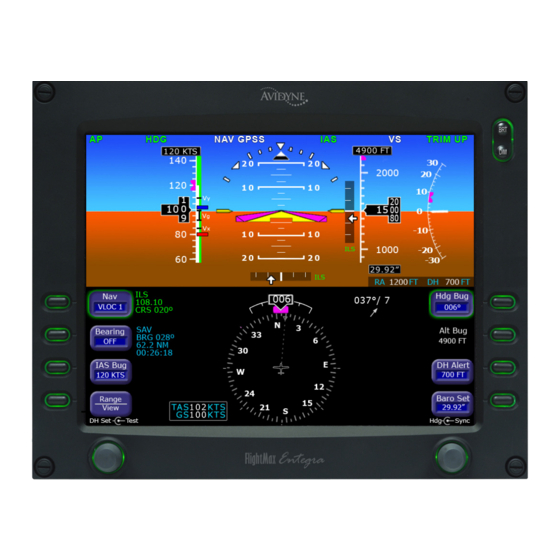
EXP5000 Buttons and Knobs, page 15 ● 2.1 EXP5000 Overview This section provides an overview of the Envision EXP5000. Figure 1. The Envision EXP5000 PFD 1) Brightness Control (BRT/DIM)—Allows you to adjust the display brightness. Press the top button to brighten the display;... - Page 10 EXP5000 Overview 2) Upper Half Display—The upper half of your EXP5000 displays information about your aircraft attitude, autopilot status (when equipped), navigation and more. This section includes the following: Autopilot annunciations ■ Attitude Direction Indicator (ADI) ■ Airspeed Indicator (ASI) ■...
-
Page 11: Exp5000 Upper Half Display
EXP5000 System Overview 2.2 EXP5000 Upper Half Display Figure 2. EXP5000 Upper Half Display Symbols Upper Half Display The upper portion of the EXP5000 contains the following information: 1) Autopilot Annunciations—If your aircraft is equipped with an S- TEC 55SR, 55X, or Intelliflight 2100 autopilot, autopilot annunciations will appear across the top of the PFD. - Page 12 EXP5000 Upper Half Display knots or 5 knots/20 knots as configured for your aircraft by the avionics installer. Major graduations are labeled. Likewise, the airspeed tape ranges are set for your aircraft by the avionics installer. The airspeed tape has the following color bands: Band Meaning Color...
- Page 13 EXP5000 System Overview ±90° is represented by small circles. ■ Large chevrons, described in Section 3.7 Precision Flying ■ with EXP5000, are only visible at excessive pitch angles and point toward the horizon (above +50° and below -30°). 7) Aircraft Reference Symbol (ARS)—The ARS is fixed on the display and provides a reference from which you can determine aircraft attitude.
- Page 14 EXP5000 Upper Half Display The localizer signal has been received. ■ Or (if used with Garmin 400W/500W navigator) The Nav source is GPS ■ GPS horizontal deviation data has been received ■ The source of the HDI data is displayed immediately to the right of the HDI (e.g., LOC, ILS or GPS).
- Page 15 EXP5000 System Overview 13) Vertical Speed Indicator (VSI)—Displays the vertical speed in Feet per Minute (fpm). The VSI generally shows ±2,000 fpm VSI scale. Scale graduations display every 100 fpm between ±1,000 fpm. For higher power aircraft, the VSI shows ±3,000 fpm VSI scale.
- Page 16 EXP5000 Upper Half Display Labeled VSpeeds and V labels are shown at the correct airspeeds for the Best Angle of Climb speed (V ) and Best Rate of Climb speed (V ). V and V are adjusted based on density altitude, as described in the Airspeeds for Normal Operations section of your aircraft Pilot Operating Handbook.
-
Page 17: Exp5000 Lower Half Display
EXP5000 System Overview 2.3 EXP5000 Lower Half Display The lower half of your EXP5000 provides navigation information, PFD control softkeys, and air data. The Horizontal Situation Indicator (HSI) displays as either a full 360° circle or as a 120° arc (See Figure 4 on page 12). All lower-half display features can appear in either the 360°... - Page 18 EXP5000 Lower Half Display 3) Wind Vector—Displays the current wind speed and wind direction. The arrow indicates the direction of the wind relative to the current aircraft heading. ➥ After you turn, there will be a lag of several seconds in updating current wind speed and direction.
- Page 19 EXP5000 System Overview ➥ To take the guesswork out of determining proper crab angles for wind corrections, align the projected track line with the desired course. Note: In dual-PFD equipped aircraft, differences between the two wind vectors during light winds are normal. 6) Bearing Pointer—The blue dual-line bearing pointer is associated with the Bearing source and displays the current bearing to the Bearing waypoint (GPS 1 or GPS 2) or to the...
- Page 20 EXP5000 Lower Half Display 13) MSG Annunciator—Illuminates when there is a message on the GPS navigator. 14) WPT Annunciator—Illuminates when the GPS navigator detects the approaching of a waypoint. Entegra EXP5000 PFD -14- 600-00157-000 Rev. 06...
-
Page 21: Exp5000 Buttons And Knobs
2.4 EXP5000 Buttons and Knobs Left Buttons and Knob The left-hand buttons and knob on the Envision EXP5000 allow you to set the navigation configuration and course. The left button configuration is determined by your aircraft’s autopilot and whether a radar altimeter is installed. - Page 22 EXP5000 Buttons and Knobs VHF navigator system, the available sources are: GPS 1, VLOC 1, GPS 2, and VLOC 2. 2) Bearing (Secondary Navigation)—Controls the source for the Bearing Pointer and adjacent data block. In a dual GPS/VHF navigator system, the available sources are: GPS 1, VLOC 1, GPS 2, VLOC 2, ADF (if available), and OFF.
- Page 23 EXP5000 System Overview 5) Left Knob—The function of the left knob changes depending on the enabled button. When the IAS Bug is enabled, push IAS ■ Bug to display the IAS knob label: Push—Syncs the setting to the current airspeed. After ◆...
- Page 24 EXP5000 Buttons and Knobs Nav and Bearing Data Blocks—The Nav data block content varies depending on the source, as follows: Table 2.3 Primary Navigation Source NAV Source Data Block Format GPS 1 or GPS 2 Waypoint Identifier ■ Desired Track to Waypoint ■...
- Page 25 Hdg Bug rotate the knob to set the Alt Bug VSI Bug, DH Alert, Baro Set buttons. Avidyne recommends that you always select the desired button just before you use the knob. 600-00157-000 Rev. 06 -19- Entegra EXP5000 PFD...
- Page 26 EXP5000 Buttons and Knobs Other autopilots No Radar Altimeter S-Tec 1500 or Intelliflight 2100 autopilot Set Alt & VSI with radar altimeter bugs on autopilot Figure 6. Right Button and Knob Configurations 1) Heading Bug (Hdg Bug)—Controlled by the right knob when Hdg Bug is selected, the notched part of the magenta bug symbol indicates the current Heading Bug value.
- Page 27 EXP5000 System Overview 2) Altitude Bug (Alt Bug)—Controlled by the right knob when you select Alt Bug. The notched part of the magenta bug symbol indicates the current altitude preselect value. When the selected value is outside the current altimeter field of view, the Bug is positioned at the appropriate end of the tape and remains in partial view (left).
- Page 28 EXP5000 Buttons and Knobs Blank—If your aircraft is equipped with an S-TEC 1500 but ■ does not have a radar altimeter, this button is blank and has no function. Note: If your aircraft is equipped with an S-TEC 2100 Autopilot IntelliFlight and a radar altimeter, then the VSI Bug button does not display on the PFD and the VSI Bug can only be set from the Autopilot.
- Page 29 EXP5000 System Overview Table 2.5 summarizes the right knob settings: Table 2.5 Right Knob Settings Active Button Knob Label Rotary Action Push Action Hdg Bug Sets Heading Bug Syncs Heading Bug to current magnetic heading. Alt Bug Sets Altitude Bug Syncs Altitude Bug to nearest 100’.
- Page 30 EXP5000 Buttons and Knobs This page intentionally left blank. Entegra EXP5000 PFD -24- 600-00157-000 Rev. 06...
-
Page 31: Flying With The Exp5000
3 Flying with the EXP5000 3.1 Introduction This chapter provides information needed to use the EXP5000, and includes the following sections: Starting the EXP5000, page 26 ● EXP5000 Alignment Messages, page 27 ● Setting Up the HSI, page 30 ● Using GPS/VHF Systems with the EXP5000, page 32 ●... -
Page 32: Starting The Exp5000
Starting the EXP5000 3.2 Starting the EXP5000 The EXP5000 includes a solid state Air Data and Attitude Heading Reference System (ADAHRS) which requires an alignment time before you are ready for flight. The EXP5000 is designed to operate during engine start and shut down procedures. -
Page 33: Exp5000 Alignment Messages
Flying with the EXP5000 EXP5000 Alignment Messages Note: For faster alignments (3 minutes or less), Avidyne recommends that you do not move the aircraft until alignment is complete. The OK TO TAXI message provides increased flexibility during ground operations, but it may extend overall alignment time. - Page 34 UNABLE TO COMPLETE ALIGNMENT Contact an Avidyne Entegra Certified Service Center. NO COMM. WITH MAGNETOMETER Note: If any error message continues to display, contact an Avidyne Entegra Certified Service Center. Mag Cal Error If the following alert is displayed, contact an Avidyne Entegra Certified Service Center as soon as practical.
-
Page 35: Startup Settings
Flying with the EXP5000 3.3 Startup Settings Figure 8. Default Startup Settings When powered up, the Envision EXP5000 starts with the following default values: Hdg Bug, Alt Bug, Baro Set—The value from just before ● previous shutdown Map Range, Map View—The setting from just before previous ●... -
Page 36: Setting Up The Hsi
Setting Up the HSI 3.4 Setting Up the HSI The Envision EXP5000 can integrate with single or dual GNS 400/ 500-series GPS or GPS/VHF navigator systems. When your EXP5000 PFD is installed, it is configured for the number and type of navigator systems on board. - Page 37 Flying with the EXP5000 HSI will display the appropriate course deviation indicator. The moving map from the associated GPS will still be displayed. For more information about the Wind Vector and the HSI moving map display, see Section 2.3, "EXP5000 Lower Half Display" on page 11 Use the Bearing button to select the Nav source for the blue double- line bearing pointer.
-
Page 38: Using Gps/Vhf Systems With The Exp5000
GPS to VLOC and back, the Nav source on the EXP5000 changes to match. ➥ Avidyne recommends that you use the CDI button on GPS 1 to toggle the Nav source back and forth, especially for dual-GPS installations where the PFD Nav button cycles through all four... -
Page 39: Using The S-Tec 55X Autopilot With The Exp5000
Flying with the EXP5000 3.6 Using the S-TEC 55X Autopilot with the EXP5000 If your aircraft is equipped with an S-TEC 55X Autopilot, the EXP5000 provides the following: Flight Director steering command bars ● Autopilot Bugs that are functional and can control the autopilot ●... - Page 40 Using the S-TEC 55X Autopilot with the EXP5000 AP (Autopilot) Mode - There are no Flight Director steering ● command bars and only the AP annunciation appears on the PFD. The autopilot flies the aircraft. FD (Flight Director) Mode - The Flight Director steering ●...
- Page 41 GPS Roll Steering Mode (GPSS Mode) - In GPSS mode, the ● autopilot flies the active flight plan of the selected GPS (Nav = GPS 1 or GPS 2). Because GPSS is more accurate, Avidyne recommends that for navigation, you use GPSS mode during autopilot operations.
- Page 42 Using the S-TEC 55X Autopilot with the EXP5000 Do not use GPSS mode on the final approach segment of a VLOC approach (ILS, LOC or non-GPS-overlay VOR). You must select NAV mode (and clear GPSS mode) prior to the turn onto the final approach course. Vertical Modes Note: One of the Horizontal Modes (HDG or NAV) must be engaged on the autopilot control head before you can engage a vertical mode.
- Page 43 Flying with the EXP5000 As the target altitude is approached, the VSI Bug will automatically move toward zero and will become hollow when the target altitude is captured. At the target altitude, the delta-shaped aircraft reference symbol is tucked into the Flight Director command bars. When engaging the Altitude Capture Mode, confirm that both ALT and VS are engaged on the autopilot.
- Page 44 Using the S-TEC 55X Autopilot with the EXP5000 Failure with Dual PFDs In a dual-PFD installation, the Nav Relay automatically connects the remaining PFD to the autopilot. The remaining PFD provides NAV data to the autopilot which, if set to GPSS mode, will fly as commanded.
-
Page 45: Using The S-Tec 1500 Autopilot With The Exp5000
Flying with the EXP5000 3.7 Using the S-TEC 1500 Autopilot with the EXP5000 If your aircraft is equipped with an S-TEC 1500 Autopilot, the EXP5000 provides the following: Flight Director steering command bars ● Autopilot bugs, which display, but cannot be controlled from the ●... - Page 46 Using the S-TEC 1500 Autopilot with the EXP5000 S-TEC 1500 Horizontal Modes This section describes horizontal and flight director modes supported by the EXP5000. Note: The autopilot can be coupled only to a Nav source selected on the PFD; it cannot be coupled to a Bearing source. Heading Capture/Hold Mode—Press the Hdg Bug button on the ●...
- Page 47 Flying with the EXP5000 AP (Autopilot) and FD (Flight Director) Modes The EXP5000 supports the AP (Autopilot) and FD (Flight Director) modes for S-Tec 1500 autopilots. In FD-equipped aircraft, single-cue FD steering command bars display the flight profile commanded by the autopilot.
-
Page 48: Using The S-Tec Intelliflight 2100 Autopilot With The Exp5000
Using the S-TEC IntelliFlight 2100 Autopilot with the EXP5000 3.8 Using the S-TEC IntelliFlight 2100 Autopilot with the EXP5000 If your aircraft is equipped with an S-TEC Intelliflight 2100 Autopilot, read this section for information on how the EXP5000 operates with the S-Tec IntelliFlight 2100 autopilot. - Page 49 Flying with the EXP5000 Table 3.8 IntelliFlight 2100 Annunciations Active Armed Control Active Armed Trim Status Lateral Lateral Wheel Vertical Vertical Status Mode Mode Steering Mode Mode AP INIT ROLL PITCH TRIM UP AP FAIL TRIM DN FAIL NAV GPSS NAV GPSS AP RDY APR GPSS ALT HOLD...
- Page 50 Using the S-TEC IntelliFlight 2100 Autopilot with the EXP5000 Nav/Apr Mode—Press the NAV button on the autopilot control ● head to engage Nav mode. If GPS (Nav=GPS 1 or GPS 2) is the selected nav source on ■ the PFD, the autopilot will track the active flight plan using GPS roll steering and will display “NAV GPSS”.
- Page 51 Flying with the EXP5000 FD (Flight Director) Mode - The Flight Director steering ● command bars are green and the FD annunciation appears on the PFD In FD mode, the command bars show you where to steer, but you need to guide the aircraft so that the Aircraft Reference Symbol (ARS) is tucked into the steering command bars.
-
Page 52: Using Other Autopilots With The Exp5000 (Pfd 530-00200-() Software Only)
Using Other Autopilots with the EXP5000 (PFD 530-00200-() software only) 3.9 Using Other Autopilots with the EXP5000 (PFD 530-00200-() software only) The prevous sections describe how the S-TEC 55X, S-Tec 1500, and S-Tec Intelliflight 2100 autopilots work with the EXP5000. This section describes features that the EXP5000 supports with other autopilots. - Page 53 GPS (NAV = GPS1 or GPS2). When you engage GPSS mode on the autopilot, the autopilot flies the GPS steering commands from the selected GPS. Avidyne recommends that you use GPSS mode as the Nav Mode during autopilot operations to provide a higher level of accuracy.
- Page 54 Using Other Autopilots with the EXP5000 (PFD 530-00200-() software only) If a VLOC is selected in NAV on the PFD and GPSS mode is engaged on the autopilot, the autopilot will track the active flight plan in GPS 1 if VLOC 1 is selected or GPS 2 if VLOC 2 is selected.
- Page 55 Flying with the EXP5000 Operating the Autopilot During a PFD Failure In the unlikely event of a total PFD failure in n aircraft with one PFD, switch the Nav Relay to connect GPS 1 to the autopilot. By doing this, the GPS will provide NAV data to the autopilot which, if set to GPSS mode, will fly flight plan activated in the GPS.
-
Page 56: Precision Flying With Exp5000
Precision Flying with EXP5000 3.10 Precision Flying with EXP5000 his section describes several techniques which take advantage of the EXP5000’s features to produce precision flight performance. Obtaining Level Flight You can obtain level flight by placing the apex of the yellow delta- shaped reference symbol a the pitch angle where the altitude trend vector is not displayed and the VSI reads zero (0). - Page 57 Flying with the EXP5000 Using Trend Indicators Use the trend indicators to capture and maintain a desired airspeed and altitude by adjusting the pitch and/or power to the airspeed or altitude you want. This results in a smooth capture of the desired airspeed and altitude.
-
Page 58: Using The Exp5000 For Approaches
HDI and VDI will automatically display when applicable localizer and glideslope signals are received. No pilot action is required. Avidyne recommends that you set the inbound course using the EXP5000 Course Set knob to serve as reference during the localizer intercept and tracking. - Page 59 Flying with the EXP5000 Flying a WAAS Approach The EXP5000 is designed to take full advantage of the WAAS approach features provided in GNS-400W/500W series GPS or GPS/ VHF navigators (Figure 13). Figure 13. Flying a WAAS Approach When GPS is selected as the primary navigation source and the selected 400W/500W is providing guidance for a LPV, L/VNAV, and LNAV+V approach, the PFD provides horizontal and vertical guidance by means of the HDI and VDI.
- Page 60 Using the EXP5000 for Approaches Flying an Autopilot-Coupled WAAS Approach To perform an autopilot-coupled GPS WAAS approach, do the following: Ensure that the nav source is set to GPS and that the selected ● navigator has the approach loaded and activated. Autopilot should remain in GPSS mode until intercepting the final ●...
- Page 61 Flying with the EXP5000 Avidyne recommends that you set the Altitude Bug to the published approach decision altitude to serve as a visual reference during the approach. Note: For maximum situational awareness during all types of precision and non-precision instrument approaches, always select and activate the approach in the Navigator.
- Page 62 Using the EXP5000 for Approaches 4) Just prior to reaching MDA, select ALT on the autopilot to command altitude hold. Flying a Back Course Localizer Approach The EXP5000 is designed to fully support flying back course localizer approaches. To perform a back course localizer approach, ensure the front course value is set via the EXP5000 Course Set knob.
-
Page 63: Invalid Sensors And Error Conditions
4 Invalid Sensors and Error Conditions When the data coming into the EXP5000 is unavailable or otherwise invalid, the EXP5000 provides appropriate warnings and messages. This section discusses the following topics: Invalid Air Data, page 58 ● Invalid Heading, page 59 ●... -
Page 64: Invalid Air Data
3) True airspeed data is removed and replaced with dashes. If invalid air data occurs, use the mechanical backup airspeed indicator and altimeter. Avidyne recommends that you cross reference the EXP5000 attitude to the backup ADI when flying with invalid air data. -
Page 65: Invalid Heading
Invalid Sensors and Error Conditions 4.2 Invalid Heading Figure 15. Invalid Heading If valid heading data becomes unavailable, heading data and HSI navigation data are removed from the display and replaced with a red Note: Refer to the aircraft compass for heading. Refer to the EX5000 MFD or GPS Navigator for ground track and flight plan. -
Page 66: Crosscheck Monitor
Crosscheck Monitor 4.3 Crosscheck Monitor Figure 16. Crosscheck Monitor The Envision EXP5000 comes equipped with a self-check monitor. When this monitor detects a condition that does not warrant removal of data, a CROSSCHECK ATTITUDE warning message displays. When this message is displayed, scan all backup instruments and auxiliary instruments (backup attitude indicator, backup airspeed indicator, and back up altimeter) to crosscheck the aircraft attitude. -
Page 67: Warmstart Conditions
Invalid Sensors and Error Conditions 4.4 Warmstart Conditions The EXP5000 is capable of performing a warmstart from a fully aligned condition when subjected to a power loss of less than 30 seconds. In this event, the “PLEASE STANDBY” message in the warmup box is displayed for approximately 2 seconds followed by the “ATTEMPTING QUICK RESTART”... -
Page 68: Recoverable Attitude
Recoverable Attitude 4.5 Recoverable Attitude Figure 18. Recoverable Attitude Situation If a recoverable attitude data failure occurs: All normal button labels are removed. 2) Attitude data is removed from the display and replaced with a red 3) A Fast Erect button label and message displays. When you press Fast Erect, the message will change to “Maintain straight and level flight”... -
Page 69: Invalid Attitude & Heading
Invalid Sensors and Error Conditions 4.6 Invalid Attitude & Heading Figure 19. Invalid Attitude and Heading If valid attitude and heading data becomes unavailable, attitude data, wind vector data, heading data, and HSI navigation data are removed from the display. Note: You may be able to recover from a failed attitude condition by pulling both PFD circuit breakers for less than 20 seconds. -
Page 70: Nav Source Crosscheck
Nav Source Crosscheck 4.7 Nav Source Crosscheck When receiving valid navigation information from two radios tuned to the same navigation aid, the EXP5000 compares the data from the two and provides an alert if there is a miscompare. This comparison is only done when one of the radios is selected as the primary navigation source. -
Page 71: Loss Of Communication With Autopilot
20 seconds after the autopilot is turned on. If the message appears after the autopilot has initialized, cycle power to the PFD. If the problem persists, contact an Avidyne Entegra Certified Service Center as soon as practical. 600-00157-000 Rev. 06 -65-... - Page 72 Loss of Communication with Autopilot This page intentionally left blank. Entegra EXP5000 PFD -66- 600-00157-000 Rev. 06...
-
Page 73: Using Dual Pfds
5 Using Dual PFDs This section discusses features specific to aircraft equipped with dual PFDs, as follows: Selecting the ADAHRS Source, page 67 ● Synchronized and Non-synchronized Controls, page 69 ● Pilot Priority Switch, page 71 ● Dual PFD Error Conditions, page 72 ●... - Page 74 To locate the ADAHRS Source Selection switch, see the Pilot’s Operating Handbook for your aircraft. Note: When both PFDs are operating normally, Avidyne recommends that you set the ADAHRS source selection switch so that each PFD displays its own ADAHRS data.
-
Page 75: Synchronized And Non-Synchronized Controls
Using Dual PFDs 5.2 Synchronized and Non-synchronized Controls When equipped with dual PFDs, some controls are synchronized between the two PFDs to reduce confusion and improve situational awareness. For these controls, adjusting any of the settings on one PFD also changes the other PFD. Figure 24. - Page 76 Synchronized and Non-synchronized Controls Table 5.9 Dual PFD Synchronized Controls Synchronized Not Synchronized Primary Nav Source selection Bearing Nav Source Course setting (if supported by HSI views selected Nav source and mode) Hdg Bug Alt Bug IAS Bug (if available) DH Alert (if available) Baro Setting Note: While the bugs that control the autopilot can be set by either PFD, the...
-
Page 77: Pilot Priority Switch
Using Dual PFDs 5.3 Pilot Priority Switch On dual-PFD equipped aircraft, the Pilot Priority switch mounted in the flightdeck instrument panel allows you to inhibit the controls on the Copilot PFD when a non-pilot is in the right-hand seat. See your aircraft Pilot’s Operating Handbook to locate the Pilot Priority switch. -
Page 78: Dual Pfd Error Conditions
Dual PFD Error Conditions 5.4 Dual PFD Error Conditions ADAHRS Miscompares In dual-PFD equipped aircraft, the two PFDs compare their ADAHRS measurements for fault detection. If airdata, attitude, or heading miscompare occurs, both PFD's will display the appropriate warning message adjacent to the affected instrument. Figure 26. - Page 79 Using Dual PFDs If you see the “No COM with Copilot PFD” error, a communication failure has occurred and the following dual PFD functions are no longer available: ADAHRS Source Selection ● Synchronize Controls ● ADAHRS Comparison Monitoring. ● Vertical Modes with S-TEC 55X Autopilot The vertical modes of the S-TEC 55X Autopilot (Alt Hold, Alt Capture, VS Mode, and so on) are wired to the pilot PFD only.
- Page 80 Dual PFD Error Conditions This page intentionally left blank. Entegra EXP5000 PFD -74- 600-00157-000 Rev. 06...
- Page 81 Copyright This document is applicable to Software Part Numbers 530-00194-000 and 530-00200-(). Copyright © 2008 Avidyne Corporation. All rights reserved. All trademarks and trade names are the property of their respective owners. All materials are copyrighted including images that represent this software. This manual has been provided pursuant to an agreement containing restrictions on its use.
- Page 82 (c) The Product has not been altered in any manner other than as previously authorized by Avidyne in writing; and (d) Repairs to the Product have not been made by anyone other than Avidyne or an Avidyne authorized service facility.
- Page 83 RELATED TO PRODUCTS NOT MANUFACTURED BY AVIDYNE OR REGARDING OR RELATED TO THE PERFORMANCE OR RELIABILITY OF ANY SUCH PRODUCT, EITHER ALONE OR WHEN USED WITH ANY PRODUCT MANUFACTURED BY AVIDYNE, OR THE SUITABILITY OF ANY SUCH PRODUCT FOR USE WITH ANY PRODUCT MANUFACTURED BY AVIDYNE.
- Page 84 THE FOREGOING PARAGRAPHS DEFINE AND LIMIT AVIDYNE'S SOLE RESPONSIBILITY AND LIABILITY AND PURCHASER'S SOLE AND EXCLUSIVE REMEDIES RELATED TO THE PRODUCT. Some jurisdictions may not allow the exclusion or limitation of warranties or liabilities, in which case the above limitations or exclusions, or some of them, may not apply in those jurisdictions.
- Page 85 FAA or other governmental agency or as a part of a court order. Avidyne makes no commitment to review or share the information contained within the data files with you, and you agree that you have no expectation that this information will be reviewed or shared.
- Page 86 Computer Software clause at DFARS 52.227-7013, and when applicable subparagraphs (a) through (d) of the Commercial Computer-Restricted rights clause at FAR 52.227-19, and in similar clauses in the NASA FAR Supplement. - Avidyne Corporation, 55 Old Bedford Road, Lincoln, MA 01773. Export Law Assurances...
- Page 87 If you do not agree to the terms of this license, Avidyne is unwilling to license the product to you. In such event, you may not use or copy the product, and you should promptly contact Avidyne for instructions on return of the unused product(s) for a refund.
- Page 88 This page intentionally left blank. Entegra EXP5000 PFD -82- 600-00157-000 Rev. 06...
- Page 90 AVIDYNE CORPORATION 55 Old Bedford Road Lincoln, MA 01773 Telephone: 781-402-7400 Toll Free: 800-AVIDYNE (800-284-3963) FAX:781-402-7599 www.avidyne.com P/N 600-00157-000 Rev. 06 August 29, 2008...
Need help?
Do you have a question about the Envision EXP5000 and is the answer not in the manual?
Questions and answers