Table of Contents
Advertisement
Advertisement
Table of Contents

Subscribe to Our Youtube Channel
Related Manuals for Avidyne Entegra EXP5000


Summary of Contents for Avidyne Entegra EXP5000
- Page 1 Piper Meridian EXP5000 Primary Flight Display Pilot’s Guide 600-00104-001 Rev 01...
- Page 3 Released per ECO-05-162 Oct. 14, 2005 Updated per ECO-05-179 This document is applicable to Software Part Number 530-00177-000. All materials copyrighted including images that represent this software Copyright 2005 Avidyne Corporation. All rights reserved. 600-00104-001 Rev 01 Entegra EXP5000 PFD...
-
Page 4: Table Of Contents
Table of Contents 1 Introduction .............. 1 Notes and Warnings 1 Copyrights and Trademarks 2 AVIDYNE EXCLUSIVE LIMITED WARRANTY/LIMITATIONS ON LIABILITY ..................3 2 EXP5000 System Overview ........5 Entegra EXP5000 Overview 5 EXP5000 Upper Half Display ............7 Upper Half Display ..............7 EXP5000 Display Options........... - Page 5 Invalid Heading................45 Crosscheck Monitor..............46 Warmstart Conditions ..............48 Recoverable Attitude ..............49 Invalid Attitude & Heading ............50 Invalid Engine Data ..............51 Nav Source Crosscheck ............52 6 Software License ........... 53 600-00104-001 Rev 01 -iii- Entegra EXP5000 PFD...
- Page 6 This page intentionally blank. Entegra EXP5000 PFD -iv- 600-00104-001 Rev 01...
-
Page 7: Introduction
Notes and warnings provide guidance for the use of the EXP5000. Avidyne strongly suggests that you pay close attention to notes and warnings for your own safety. For example: Note: Notes provide useful information about how to use the EXP5000 Primary Flight Display. -
Page 8: Copyrights And Trademarks
1.2 Copyrights and Trademarks All trademarks and trade names are the property of their respective owners. All materials copyrighted including images that represent this software. Copyright 2005 Avidyne Corporation. All rights reserved. Entegra EXP5000 PFD 600-00104-001 Rev 01... -
Page 9: Avidyne Exclusive Limited Warranty/Limitations On Liability
(c) The Product has not been altered in any manner other than as previously authorized by Avidyne in writing; and (d) Repairs to the Product have not been made by anyone other than Avidyne or an Avidyne authorized service facility. - Page 10 RELATED TO PRODUCTS NOT MANUFACTURED BY AVIDYNE OR REGARDING OR RELATED TO THE PERFORMANCE OR RELIABILITY OF ANY SUCH PRODUCT, EITHER ALONE OR WHEN USED WITH ANY PRODUCT MANUFACTURED BY AVIDYNE, OR THE SUITABILITY OF ANY SUCH PRODUCT FOR USE WITH ANY PRODUCT MANUFACTURED BY AVIDYNE.
-
Page 11: Exp5000 System Overview
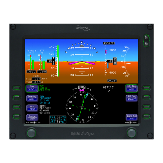
EXP5000 Lower Half Display, page 12 EXP5000 Buttons and Knobs, page 15 2.1 Entegra EXP5000 Overview This section provides an overview of the Entegra EXP5000 window. Figure 1. The Entegra EXP5000 PFD 1) Brightness Control (BRT/DIM)—Allows you to adjust the display brightness. - Page 12 Left button and knob functions are described in Left Buttons and Knob, on page 15. Right button and knob functions are described in Right Buttons and Knob, on page 18. Entegra EXP5000 PFD 600-00104-001 Rev 01...
-
Page 13: Exp5000 Upper Half Display
(red) area, the analog indicator bar and numeric readout out display in red. ITT—Displays current engine ITT in °C. A numeric display below the ITT analog indicator displays the ITT value to the 600-00104-001 Rev 01 Entegra EXP5000 PFD... - Page 14 Full scale deflection is the width of the trapezoid. 8) Pitch Ladder—The pitch ladder is marked as follows: Every 2 1/2° within the range of ± 20°. Every 5° from +20° to +50° and -20° to -30°. Entegra EXP5000 PFD 600-00104-001 Rev 01...
- Page 15 HDI (e.g. LOC or ILS). If the signal is lost, the HDI is replaced with a red and the source letters turn red. To remove the HDI, change either the NAV source or the VOR/ LOC frequency. 600-00104-001 Rev 01 Entegra EXP5000 PFD...
-
Page 16: Exp5000 Display Options
Labeled VSpeeds Under high power conditions, the V and V labels are shown at the correct airspeeds for the Best Angle of Climb speed (V ) and Best Rate of Climb speed (V Entegra EXP5000 PFD -10- 600-00104-001 Rev 01... - Page 17 Note: If your aircraft POH lists Best Glide airspeeds for multiple gross weights, V is displayed as a range between the highest and lowest Best Glide airspeed. Make sure you consult the POH for the correct Best Glide airspeed for a particular gross weight. 600-00104-001 Rev 01 -11- Entegra EXP5000 PFD...
-
Page 18: Exp5000 Lower Half Display
The arrow indicates the direction of the wind relative to the current aircraft heading. After you turn, there will be a lag of several seconds in updating current wind speed and direction. Entegra EXP5000 PFD -12- 600-00104-001 Rev 01... - Page 19 The moving map will also display waypoints and labels of an approach and hold. 9) HSI Map Range—When the moving map is selected for display on the HSI via the View knob, the outer and inner rings of the 600-00104-001 Rev 01 -13- Entegra EXP5000 PFD...
- Page 20 11) Air Data Data Block—Displays: True Airspeed (TAS) in knots Ground Speed (GS) in knots Outside Air Temperature (OAT) in degrees Celsius Figure 4. EHSI Arc (120°) View Entegra EXP5000 PFD -14- 600-00104-001 Rev 01...
-
Page 21: Exp5000 Buttons And Knobs
EXP5000 Buttons and Knobs 2.4 EXP5000 Buttons and Knobs Left Buttons and Knob The left-hand buttons and knob on the Entegra EXP5000 allow you to set the navigation configuration and course. The Nav (Primary Navigation) button is enabled by default (the enabled button has a green rim). - Page 22 GPS in Auto-Leg mode None GPS 1 or GPS 2 GPS in OBS mode VLOC 1 or VLOC 2 Tuned NavAid is a VOR VLOC 1 or VLOC 2 Tuned NavAid is an ILS or LOC Entegra EXP5000 PFD -16- 600-00104-001 Rev 01...
-
Page 23: Nav, Bearing, And Aux Data Blocks
VLOC 1 or VLOC 2 (VOR Tuned) “VOR” VOR Frequency Bearing to station VLOC 1 or VLOC 2 (ILS or LOC Tuned) “ILS” or “LOC” Localizer Frequency ADF (if available) ADF Frequency (if available) ADF Bearing Blank 600-00104-001 Rev 01 -17- Entegra EXP5000 PFD... -
Page 24: Right Buttons And Knob
Hdg Bug rotate the knob to set the buttons. Avidyne Alt Bug Baro Set recommends that you always select the desired button just before you use the knob. Figure 6. Right Buttons and Knob Entegra EXP5000 PFD -18- 600-00104-001 Rev 01... - Page 25 Bug setting. When Alt Bug is selected, the numbers appear as black on magenta. 5) Barometric Correction Setting (Baro Set)—Controlled by the right knob when you select Baro Set, the value indicates the 600-00104-001 Rev 01 -19- Entegra EXP5000 PFD...
- Page 26 Push Action Hdg Bug Sets Heading Bug Syncs Heading Bug to current magnetic heading. Alt Bug Sets Altitude Bug Syncs Altitude Bug to nearest 100’. Baro Set Sets Baro Sets Baro to 29.92. Entegra EXP5000 PFD -20- 600-00104-001 Rev 01...
-
Page 27: Flying With The Exp5000
EXP5000 Alignment Messages, page 23 Setting Up the HSI, page 26 Using GPS/VHF Systems with the EXP5000, page 27 Controlling the Autopilot, page 28 Precision Flying with EXP5000, page 30 Using the EXP5000 for Approaches, page 33 600-00104-001 Rev 01 -21- Entegra EXP5000 PFD... -
Page 28: Starting The Exp5000
Table 3.6 on page 23. When warm-up is complete, the message box is removed. Figure 7. Entegra EXP5000 AHRS Alignment Message Typical alignment time is 3 minutes but may take longer if the aircraft is subjected to motion. Air data (airspeed, altitude, vertical speed) will become valid prior to attitude data. -
Page 29: Exp5000 Alignment Messages
Starting the EXP5000 EXP5000 Alignment Messages Note: For faster alignments (3 minutes or less), Avidyne recommends that you do not move the aircraft until alignment is complete. The OK TO TAXI message provides increased flexibility during ground operations, but it may extend overall alignment time. -
Page 30: Ahrs Alignment Errors
Recommend One-Time Power Cycle UNABLE TO COMPLETE ALIGNMENT Contact an Avidyne Entegra Certified Service Center. NO COMM. WITH MAGNETOMETER Note: If any error message continues to display, contact an Avidyne Entegra Certified Service Center. Entegra EXP5000 PFD -24- 600-00104-001 Rev 01... -
Page 31: Startup Settings
Startup Settings 3.3 Startup Settings Figure 8. Default Startup Settings When powered up, the Entegra EXP5000 starts with the following default values: Hdg Bug, Alt Bug, Baro Set—The value from just before previous shutdown Map Range, Map View—The setting from just before previous shutdown Alt Bug Mode—Thousands mode... -
Page 32: Setting Up The Hsi
Flying with the EXP5000 3.4 Setting Up the HSI The Entegra EXP5000 can integrate with single or dual GNS 400/ 500-series GPS or GPS/VHF navigator systems. When your EXP5000 PFD is installed, it is configured for the number and type of navigator systems on board. -
Page 33: Using Gps/Vhf Systems With The Exp5000
GPS to VLOC and back, the Nav source on the EXP5000 changes to match. Avidyne recommends that you use the CDI button on GPS 1 to toggle the Nav source back and forth, especially for dual-GPS installations where the PFD Nav button cycles through all four... -
Page 34: Controlling The Autopilot
When a localizer is the active Nav source, the autopilot will automatically transition to APR mode when the localizer is captured and will display “NAV APR”. Glideslope capture is supported when the autopilot is in NAV APR and altitude hold (“ALT”) modes. Entegra EXP5000 PFD -28- 600-00104-001 Rev 01... -
Page 35: Flight Director Modes
15° in pitch with respect to the aircraft reference symbol. Autopilot Operation During PFD Failures The S-TEC 1500 requires a dual-PFD installation to operate. If either PFD fails, the autopilot cannot be engaged. 600-00104-001 Rev 01 -29- Entegra EXP5000 PFD... -
Page 36: Precision Flying With Exp5000
Deviations from an intended bank angle are extremely easy to notice with the EXP5000 ADI horizon line. Entegra EXP5000 PFD -30- 600-00104-001 Rev 01... -
Page 37: Using Trend Indicators
3) Rate of Turn Indicator—The tip of the blue rate of turn indicator displays the current rate of turn. The indicator is marked for 1/2 and full standard rate of turn. An arrowhead indicates a value beyond 1 1/2 standard rate. 600-00104-001 Rev 01 -31- Entegra EXP5000 PFD... - Page 38 4) Altitude Trend Indicator—The tip of the blue airspeed trend indicator displays the predicted altitude six seconds into the future at the current rate of change. An arrowhead indicates a value beyond the current tape field of view. Entegra EXP5000 PFD -32- 600-00104-001 Rev 01...
-
Page 39: Using The Exp5000 For Approaches
No pilot action is required for the HDI and VDI to display. Avidyne recommends that you set the inbound course using the EXP5000 Course Set knob to serve as reference during the localizer intercept and tracking. This is automatic if the Navigator system has been set to Autoslew. -
Page 40: Non-Precision Approaches
The autopilot will then track the Glidescope and localizer. Refer to the autopilot user’s guide for Glideslope capture scenarios. Avidyne recommends that you set the Altitude Bug to the published approach decision height to serve as a visual reference during the approach. - Page 41 HDI and CDI display correct sensing. There is no further pilot action required. Note: For coupled approaches, the Autopilot may have to be set to reverse mode. Please consult the Autopilot POH for proper operation. 600-00104-001 Rev 01 -35- Entegra EXP5000 PFD...
-
Page 42: Using Dual Pfds
PFD, a message displays at the center top of the PFD. As shown in the example above, the message ADAHRS 2 displays on the Pilots PFD when it is displaying the Copilot PFD’s ADAHRS. 600-00104-001 Rev 01 -36- Entegra EXP5000 PFD... - Page 43 . To locate the ADAHRS Source Selection switch, see the Pilot’s Operating Handbook for your aircraft. Note: When both PFDs are operating normally, Avidyne recommends that you set the ADAHRS source selection switch so that each PFD displays its own ADAHRS data.
-
Page 44: Synchronized And Non-Synchronized Controls
Dual PFD Synchronized Controls Synchronized Not Synchronized Primary Nav Source selection Bearing Nav Source Course setting (if supported by Aux Nav Source selected Nav source and mode) Hdg Bug HSI views Alt Bug Baro Setting Entegra EXP5000 PFD -38- 600-00104-001 Rev 01... - Page 45 Pilot PFD heading to measure its deviation. If the Copilot PFD heading differs from the Pilot PFD, the Copilot PFD may show a mismatch between the heading bug and the autopilot-controlled heading. 600-00104-001 Rev 01 -39- Entegra EXP5000 PFD...
-
Page 46: Pilot Priority Switch
Coupled—Button labels are restored, which reinstates copilot control for the Nav, Hdg Bug, Alt Bug, and Baro Set parameters as described in Section 4.2, "Synchronized and Non- synchronized Controls" on page 38. Entegra EXP5000 PFD -40- 600-00104-001 Rev 01... -
Page 47: Dual Pfd Error Conditions
If, at any point, one PFD loses contact with the other, a yellow error message will appear at the lower right corner of the HSI reading “No COM with Pilot PFD” or “No COM with Copilot PFD.” 600-00104-001 Rev 01 -41- Entegra EXP5000 PFD... - Page 48 If you see the No COM with Copilot PFD error, a communication failure has occurred and the following dual PFD functions are no longer available: ADAHRS Source Selection Synchronize Controls ADAHRS Comparison Monitoring. Entegra EXP5000 PFD -42- 600-00104-001 Rev 01...
-
Page 49: Invalid Sensors And Error Conditions
Invalid Air Data, page 44 Invalid Heading, page 45 Crosscheck Monitor, page 46 Warmstart Conditions, page 48 Recoverable Attitude, page 49 Invalid Attitude & Heading, page 50 Invalid Engine Data, page 51 Nav Source Crosscheck, page 52 600-00104-001 Rev 01 -43- Entegra EXP5000 PFD... -
Page 50: Invalid Air Data
3) Outside Air Temperature and True airspeed data are removed and replaced by dashes. If invalid air data occurs use the mechanical backup airspeed indicator and altimeter. Avidyne recommends that you cross reference the EXP5000 attitude to the backup ADI when flying with invalid air data. -
Page 51: Invalid Heading
Note: Refer to the aircraft compass for heading. Refer to the EX5000 MFD or GPS Navigator for ground track and flight plan. When heading data is determined to be valid, the display of heading and HSI navigation data will be restored. 600-00104-001 Rev 01 -45- Entegra EXP5000 PFD... -
Page 52: Crosscheck Monitor
Invalid Sensors and Error Conditions 5.3 Crosscheck Monitor Figure 18. Crosscheck Monitor The Entegra EXP5000 comes equipped with a self-check monitor. When this monitor detects a condition that does not warrant removal of data, a CROSSCHECK ATTITUDE warning message displays. - Page 53 Crosscheck Monitor Note: In dual PFD installations, the CROSSCHECK ATTITUDE message applies to the selected ADAHRS source. 600-00104-001 Rev 01 -47- Entegra EXP5000 PFD...
-
Page 54: Warmstart Conditions
There is no requirement to limit dynamic maneuvering during this warmstart attempt. Note: Two warmstart attempts in a row without a successful alignment between attempts will result in a full alignment attempt. Figure 19. Quick Restart Messages Entegra EXP5000 PFD -48- 600-00104-001 Rev 01... -
Page 55: Recoverable Attitude
At that point, all attitude data is restored. It is imperative that you obtain straight and level flight before pressing . Use the backup instruments and/or Fast Erect outside visual references to obtain straight and level conditions. 600-00104-001 Rev 01 -49- Entegra EXP5000 PFD... -
Page 56: Invalid Attitude & Heading
VMC conditions and do not re- enter IMC. Note: For autopilot-equipped aircraft, consider using the autopilot to reduce workload. Use GPSS mode to maintain the flight plan route. Entegra EXP5000 PFD -50- 600-00104-001 Rev 01... -
Page 57: Invalid Engine Data
Use engine instruments on the Multi-Function Display (MFD) or Copilot PFD, if available. If engine sensors have failed and the data is not available on the PFD or MFD, land as soon as practical. 600-00104-001 Rev 01 -51- Entegra EXP5000 PFD... -
Page 58: Nav Source Crosscheck
This comparison is only done when one of the radios is selected as the primary navigation source. Figure 23. Localizer and Glideslope Crosscheck Errors Figure 24. VOR Crosscheck Error Entegra EXP5000 PFD -52- 600-00104-001 Rev 01... -
Page 59: Software License
Software, disk or related materials or create derivative works based upon the software or any part thereof. Title, ownership rights, and intellectual property rights in and to the Software belongs to Avidyne and its licensors. The Software is protected by the copyright laws of the United States and by international copyright treaties. - Page 60 If you do not agree to the terms of this license, Avidyne is unwilling to license the product to you. In such event, you may not use or copy the product, and you should promptly contact Avidyne for instructions on return of the unused product(s) for a refund.
- Page 61 55 Old Bedford Road Lincoln, MA 01773 Telephone: 781-402-7400 Toll Free: 800-AVIDYNE (800-284-3963) FAX:781-402-7599 www.avidyne.com P/N 600-00104-001 Rev 01 10/05 © 2005 Avidyne Corporation All Rights Reserved. Avidyne ® , FlightMax ® and CSS ™ are trademarks of Avidyne Corp.
Need help?
Do you have a question about the Entegra EXP5000 and is the answer not in the manual?
Questions and answers