Sign In
Upload
Manuals
Brands
Avidyne Manuals
Avionics Display
Envision EXP5000
Avidyne Envision EXP5000 Manuals
Manuals and User Guides for Avidyne Envision EXP5000. We have
2
Avidyne Envision EXP5000 manuals available for free PDF download: Pilot's Manual, Installation Manual
Avidyne Envision EXP5000 Installation Manual (87 pages)
Primary Flight Display
Brand:
Avidyne
| Category:
Monitor
| Size: 1 MB
Table of Contents
Table of Contents
5
General Information
9
Equipment Description
9
Technical Specification
10
PFD Unit
10
Magnetometer/Oat Sensor
10
Table 1: PFD Technical Specifications
10
Table 2: Magnetometer/Oat Sensor Technical Specifications
10
TSO Information
11
Table 3: Tsos Applicable to Pfds with 530-00200-( ) Software
11
Table 4: TSO Authorizations for Magnetometer/Oat Sensor
12
Table 5: Partial Function Tsos
12
Table 6: Function Not Covered Bytsos
13
Table 7: TSO Deviations Granted for the Applicable Tsos
13
Installation Instructions
15
General Information
15
Unpacking and Inspection
15
Additional Documents
16
Parts Required but Not Supplied
16
Table 8: Required Documents
16
Table 9: Parts Required but Not Supplied
16
Pre-Modification Planning
18
Pre-Modification Checklist
18
Requirements and Limitations
18
Table 10: Pre-Modification Checklist
18
Electrical Load Analysis
19
Table 11: 28 VDC Electrical Loads
19
Installing the Envision EXP5000 PFD
20
Installation Planning
20
Mechanical Installation
21
Figure 1: Pilot's Field of View
21
Electrical Installation
22
Table 12: PFD Connectors
22
Figure 2: PFD Connectors
22
System Setup
25
Accessing the Setup
25
Accessing the System Setup and Information
25
Figure 3: PFD Controls
25
System Page
26
Figure 4: System Page
26
Adjusting the Pitch Offset
27
Configuring the ASI (Airspeed Indicator)
28
Figure 5: Airspeed Indicator Configuration Page
28
Table 13: Required V-Speeds
29
Table 14: Optional V-Speeds
30
Avionics Page
31
Figure 6: Avionics Page, Release 7.1 and Later
31
Configuring the GNS Unit
33
Table 15: Main ARINC 429 Configuration Page
33
Table 16: Main RS232 Configuration Page
33
Table 17: VOR/LOC/GS ARINC 429 Configuration Page
34
Display Format/Units Page
35
Table 18: Display Page Options
35
Calibration Page
37
Figure 7: Calibration Page
37
Calibrating the IRU
38
Figure 8: IRU Calibration Page
38
Calibrating the Magnetometer
39
Figure 9: Initial Magnetometer Calibration Page
40
Figure 10: Final Magnetometer Calibration Page
40
Calibrating the ADU
42
Figure 11: Calibrating the ADU
42
Post-Installation Checks
45
Ground Checks
45
GPS NAV-COMM Checks
45
Table 19: Dual GPS Nav/Comm Check
45
Table 20: GPS Nav/Comm Check (1 X GNS 430W/530W, 1 X GNC-420)
46
Table 21: GPS Navigation Integration Test
46
Pitot-Static Leak Check
47
Magnetic Compass Swing
47
Star Aviation Ground Tests
47
Cleaning the EXP5000 Screen
47
Inflight Setup and Checkout
48
Autopilot Roll Centering Adjustment (S-Tec 55X or 65)
48
Autopilot Checkout
48
Star Aviation In-Flight Tests
49
Factory Service Policies
51
Technical Support
51
General Service Procedures
51
Appendix A: Environmental Qualification Forms
53
Table 22: DO-160E ENVIRONMENTAL QUALIFICATION TESTS
53
Table 23: DO-160D ENVIRONMENTAL QUALIFICATION TESTS
54
Table 24: MAGNETOMETER/OAT SENSOR RTCA/DO-160D ENVIRONMENTAL QUALIFICATION FORM
55
Appendix B: Envision 700-00006-000 PFD Dimensions
56
700-00006-000 PFD Front and Top Dimensions
56
Figure 12: PFD 700-00006-000 Top and Front View
56
700-00006-000 PFD Right and Rear Dimensions
57
Figure 13: PFD 700-00006-000 Right and Rear View
57
Appendix C: Magnetometer/Oat Sensor Dimensions
58
Figure 14: 700-00011-000 Magnetometer/Oat Sensor Dimensions
58
Appendix D: PFD Cutout Dimensions
59
Figure 15: PFD Cutout Dimensions (Landscape)
59
Figure 16: Detail A-Corner Detail
59
Appendix E: PFD Wiring Diagrams
60
Key to Electrical Symols
60
Figure 17: Key to Electrical Symbols
60
PFD Magnetometer, OAT, Power, and Lighting Interconnect
61
Figure 18: PFD Magnetometer, OAT, Power, and Lighting Interconnect
61
MFD Interconnect - RS232
62
Figure 19: MFD Interconnect - RS232
62
PFD Interconnect with GNS-430/GNS-430W/GNC-420
63
Figure 20: PFD Interconnect with GNS-430/430W/GNC-420
63
PFD Interconnect with Nav Relay, GNS-430/430W, and S-TEC 55X
64
Figure 21: PFD Interconnect with Nav Relay, GNS-430/430W, and S-TEC 55X
64
S-TEC 55X Analog Signal Interconnect
65
Figure 22: S-TEC 55X Analog Signal Interconnect
65
S-TEC 55X Digital/Discrete Signal Interconnect
66
Figure 23: S-TEC 55X Digital/Discrete Signal Interconnect
66
Autopilot / Flight Director Relay, S-TEC 55X
67
Figure 24: Autopilot / Flight Director Relay, S-TEC 55X
67
PFD Interconnect with Nav Relay, GNS-430/430W, and S-TEC 65 Autopilot
68
Figure 25: PFD Interconnect with Nav Relay, GNS-430/430W, and S-TEC 65 Autopilot
68
Analog Signal Interconnect - S-TEC 65 Autopilot
69
Figure 26: Analog Signal Interconnect - S-TEC 65 Autopilot
69
Discrete Signal Interconnect - S-TEC 65 Autopilot
70
Figure 27: Discrete Signal Interconnect - S-TEC 65 Autopilot
70
ADF Interconnect with Shadin Converter
71
Figure 28: ADF Interconnect with Shadin Converter
71
ADF Interconnect with DFS-43A
72
Figure 29: ADF Interconnect with DFS-43A
72
Radar Altimeter Interconnect
73
Figure 30: Radar Altimeter Interconnect
73
System Interconnect, Garmin 430S
74
Table 25: J732 Pin Assignments
74
Table 26: CH 0 (PFD Transmit ARINC 429 Messages) P/N 700-00006-003
74
Table 27: CH 1/CH3 (GNS430 GPS ARINC429 Messages)
75
Table 28: CH 2/CH4 (GNS430 VHF ARINC429 Messages)
76
Appendix F: System Interconnect, S-TEC 55X
77
Table 29: S-Tec 55 or 55X System Interconnect (See Figure 21 through Figure 24)
77
Table 30: CH7 Transmit (ADAHRS and Gpss/Nav Messages) P/N 700-00006-000/-002
80
Table 31: CH7 Transmit (ADAHRS and Gpss/Nav Messages) P/N 700-0006-003
80
Appendix G: System Interconnect, S-Tec 65 Autopilot
81
Table 32: S-Tec 65 Autopilot System Interconnect (See Figure 25 through Figure 27)
81
Appendix H: System Interconnect - External Air Data Module
83
Table 33: CH 4 External Air Data Module
83
Appendix I: System Interconnect, ADF
84
Table 34: ADF System Interconnect, KR-87 with Shadin 933752-000 (See Figure 28)
84
Table 35: ADF System Interconnect, DFS-43A (See Figure 29)
84
Advertisement
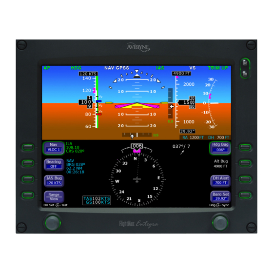
Avidyne Envision EXP5000 Pilot's Manual (90 pages)
Primary Flight Display
Brand:
Avidyne
| Category:
Avionics Display
| Size: 4 MB
Table of Contents
Table of Contents
5
1 Introduction
7
Notes and Warnings
7
2 EXP5000 System Overview
9
EXP5000 Overview
9
EXP5000 Upper Half Display
11
EXP5000 Lower Half Display
17
EXP5000 Buttons and Knobs
21
EXP5000 Overview
21
3 Flying with the EXP5000
31
Introduction
31
Starting the EXP5000
32
EXP5000 Alignment Messages
33
Startup Settings
35
Setting up the HSI
36
Using GPS/VHF Systems with the EXP5000
38
Using the S-TEC 55X Autopilot with the EXP5000
39
Using the S-TEC 1500 Autopilot with the EXP5000
45
Using the S-TEC Intelliflight 2100 Autopilot with the EXP5000
48
Using Other Autopilots with the EXP5000 (PFD 530-00200-() Software Only)
52
Precision Flying with EXP5000
56
Using the EXP5000 for Approaches
58
4 Invalid Sensors and Error Conditions
63
Invalid Air Data
64
Invalid Heading
65
Crosscheck Monitor
66
Warmstart Conditions
67
Recoverable Attitude
68
Invalid Attitude & Heading
69
Nav Source Crosscheck
70
Loss of Communication with Autopilot
71
5 Using Dual Pfds
73
Selecting the ADAHRS Source
73
Synchronized and Non-Synchronized Controls
75
Pilot Priority Switch
77
Dual PFD Error Conditions
78
Advertisement
Related Products
Avidyne Envision EX5000 Series
Avidyne Envision EX5000
Avidyne Entegra EXP5000
Avidyne Entegra EX5000
Avidyne Entegra
Avidyne FlightMax EX500
Avidyne EX600
Avidyne Entegra EX5000C
Avidyne Entegra EX5000 MFD Series
Avidyne 700-00011-000
Avidyne Categories
Avionics Display
Monitor
GPS
Marine Radio
Car Navigation system
More Avidyne Manuals
Login
Sign In
OR
Sign in with Facebook
Sign in with Google
Upload manual
Upload from disk
Upload from URL