Table of Contents
Advertisement
Quick Links
Advertisement
Table of Contents

Subscribe to Our Youtube Channel
Related Manuals for WDM PI


Summary of Contents for WDM PI
- Page 1 Operation Manual In-Line Vertical Pump PI...
- Page 2 Care must also be taken to prevent ignition of flammable fluids or other material. Information in this manual is believed to be reliable, but it is not guaranteed by WDM Pumps as to its completeness or accuracy.
-
Page 3: Table Of Contents
PI Operation Manual SECTION ONE - PRODUCT DESCRIPTION ................6 1.1 INTRODUCTION ......................7 1.2 PUMP CASE, IMPELLER, AND ADAPTER ..............7 1.2.1 Pump Case .........................7 1.2.2 Impeller ........................7 1.2.3 Adapter ........................7 1.3 MECHANICAL SEAL CHAMBER ..................7 SECTION TWO - SAFETY ......................8 2.1 IDENTIFICATION OF SAFETY INSTRUCTIONS IN THE OPERATING MANUAL ..8... - Page 4 SECTION SIX – MAINTENANCE ....................24 6.1 DISASSEMBLY .........................24 6.2 INSPECTION AND CLEANING ..................26 6.3 REASSEMBLY ........................26 6.3.1 PI Mechanical Seal Option .....................26 6.3.2 PI Packing Option ......................44 SECTION SEVEN - SPARE PARTS ....................48 SECTION EIGHT - PARTS INFORMATION ...................49 SECTION NINE - TROUBLESHOOTING CHART ................51...
-
Page 5: Section One - Product Description
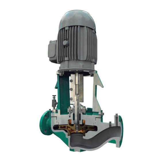
WDM Pumps of type PI are In-Line Vertical pumps, vertically (radially) split case, centerline supported with an overhung impeller. The PI is a single stage, single suction pump. For these pumps, rotation is clockwise as viewed from the motor (coupling) end. These pumps have a top Pull-Out which simplifies maintenance. -
Page 6: Pump Case, Impeller, And Adapter
The bracket has a drainer plug, which avoids accumulation of condensed water inside the pump. SEAL CHAMBER The PI pump has an outside balanced mechanical seal option, inside unbalanced mechanical seal option, as well as packaging option. Mechanical seal (stationary part) holder with cooling system. www.wdmpumps.com... -
Page 7: Section Two - Safety
PI Operation Manual 2. SECTION TWO - SAFETY This operation manual gives basic instructions that should be observed during installation, operation and maintenance of the pump. It is therefore imperative that this manual be read by the responsible personnel/operator prior to assembly and commissioning. -
Page 8: Qualification And Training Of Operating Personnel
If the staff does not have the necessary knowledge, they must be trained and instructed. Training may be performed by a WDM Pumps representative on behalf of the plant operator. Moreover, the plant operator is to make sure that the contents of the operating manual are fully understood by the personnel. -
Page 9: Safety Instructions Relevant For Maintenance, Inspection And Assembly Work
Modifications may be made to the machine only after consultation with a WDM Pumps representative. Using spare parts and accessories authorized by WDM Pumps is in the interest of safety. The use of parts not authorized by the dealer exempt the manufacturer from any liability, voiding the warranty. -
Page 10: Section Three - Transport & Storage
2. Remove unit only by properly supporting the wooden shipping skid. 3. After unloading, inspect the pump, check the shipment against the packing list, and report damages or shortages immediately to freight carrier and to the designated WDM Pumps representative. TRANSPORT •... -
Page 11: Storing
PI Operation Manual Figure 3.1. Correct Position of the lifting ropes or chains. On the left, to tilt the unit to a vertical position; on the right, to lift the unit. STORING If the pump is not installed immediately (within one month after shipping date), it should be safely stored prior to installation in a dry location free of dirt and grit. - Page 12 13. When the pump is to be installed, remove all the protective coatings and desiccant or drain all oils. One month before installation, a WDM Pumps representative should be employed to conduct a final inspection. To properly store the motor (driver) for periods longer than one month, follow these steps: 1.
- Page 13 PI Operation Manual 5. Upon receipt, considering that the oil-lubricated drivers are not shipped oil-filled, fill the reservoir to maximum level with properly selected oil with rust and corrosion inhibitors. Always drain the oil before moving the pump, to avoid any damages, and refill the motor on its new location.
-
Page 14: Conservation
PI Operation Manual CONSERVATION All exposed, machined, working surfaces (flanges, seals, surfaces supporting the motor), shaft ends, and the like have been cleaned and treated with anticorrosive agents. After being cleaned, all parts inside the pump housing have been sprayed with anticorrosive agents. -
Page 15: Section Four - Piping
PI Operation Manual 4. SECTION FOUR - PIPING These units are furnished for a specific service condition. Any change in the hydraulic system may affect the pump performance adversely. The connection of the piping must be carried out with utmost care; otherwise, the pumping medium can escape during operation, which can seriously endanger the operating personnel. - Page 16 PI Operation Manual 2. Remove the covers of the pump flanges. 3. Check whether the seals are correctly mounted. 4. Install a check valve and a gate valve in the discharge pipe. When the pump is stopped, the check valve will protect the pump against excessive back-flow pressure and will prevent the pump from running backward.
- Page 17 PI Operation Manual 8. Pump and pipe flanges must be parallel; they should mate together without effort, and with the bolt holes properly in line. 9. Proceed in the same way with the discharge pipe. Make sure that there are isolation block valves at the pump for each type of auxiliary piping.
-
Page 18: Section Five - Operation
PI Operation Manual 5. SECTION FIVE - OPERATION PRIMING The most common method used for warming a pump, or maintaining a standby pump in a warm condition, is the use of a warming line and orifice, thus circulating the hot pumpage through the idle pump. -
Page 19: Operating Check
PI Operation Manual The startup procedure is as follows: 1. Before starting the pump, check the security of all bolting, piping, and wiring. 2. Check all gauges, valves and instruments for proper working order. 3. Check all equipment for proper rotation. - Page 20 To monitor flow, pressure, and temperature, regular visual inspection and monitoring is advisable and/or necessary during operation. WDM Pumps recommends checking the pump constantly at regular intervals in order to detect problems early, in case they arise. The operational check routine must include minimum the following points: Beware of freely rotating parts, when the pump is in operation there is a high risk of injury.
-
Page 21: Stopping
PI Operation Manual STOPPING 1. Throttle pump discharge to minimum flow. Warning: do not close suction valve, this will cause the pump to run dry. 2. Turn the power off to the driver. 3. Close the pump discharge valve 4. Observe the run - down of the pump until full stop. -
Page 22: Long-Term Shutdown
PI Operation Manual 5.6 LONG-TERM SHUTDOWN 1. Follow the stopping procedure described in SECTION 5.4 – STOPPING. 2. While the unit is idle: a. If the plant is in an operational state, warm up and start the unit at monthly intervals (see SECTION 5.2 - STARTUP... -
Page 23: Section Six - Maintenance
6.1 DISASSEMBLY Depending on the extent of the required disassembly, follow the next steps to disassemble your PI pump. SECTION 5.4 - STOPPING. - Page 24 PI Operation Manual The use of a crane with a chain or sling to lift the motor (driver) is suggested. 10. Exercise care and remove mechanical seal as follows: a. Loosen and remove the shaft screw from the upper part of the coupling side.
-
Page 25: Inspection And Cleaning
Check for transmission elements of the coupling. 6.3 REASSEMBLY 6.3.1 PI Mechanical Seal Option Please follow the steps detailed on this section to reassemble the PI Mechanical Seal pump. To SECTION 6.3.2 reassemble the PI Packing pump refer to –... - Page 26 1. Insert the shaft key in the keyway on the impeller side of the shaft. Figure 6.1 Inserting the shaft key in the keyway on the impeller side of the shaft. In case that the pump is PI Fire or Close Coupled, the shaft must be assembled with a shaft sleeve.
- Page 27 PI Operation Manual 3. Introduce the shaft inside the impeller until it reaches the step on the shaft. Figure 6.3 Introducing the shaft inside the impeller until it reaches the step on the shaft. Place the impeller lockwasher into the shaft’s impeller side.
- Page 28 PI Operation Manual Tighten the impeller screw into the shaft’s impeller side. Figure 6.5 Tightening the impeller screw into the shaft’s impeller side. Placing the impeller-shaft assembly in the casing. Space between impeller and casing Impeller resting on casing`s bottom Figure 6.6 Placing the impeller-shaft assembly in the casing.
- Page 29 PI Operation Manual Figure 6.7 Inserting the bushing in the central bore of the adapter. Do not force the insertion of the carbon bushing beyond the limit with the hy- draulic press, as the bushing may be broken. 8. Place the corresponding gasket in the adapter; make sure to match the holes in the adapter. It is recommended to grease the gasket once in place, in order to accomplish the next reassembly step.
- Page 30 PI Operation Manual Figure 6.9 Positioning the adapter in the casing. The ears of the adapter are aligned with the suction and discharge flanges, with the drain on the adapter specifically aligned with the suction side. This arrangement will allow the cor- rect installation of the mechanical seal. Place the corresponding washers on the adapter matching the screwholes. Figure 6.10 Placing the corresponding washers on the adapter matching the screwholes.
- Page 31 PI Operation Manual Figure 6.11 Fastening the corresponding screws on the adapter. Insert the corresponding gasket of the mechanical seal into the shaft. Make sure the gasket is well positioned in the bottom of the adapter. Figure 6.12 Inserting the gasket of the mechanical seal into the shaft.
- Page 32 PI Operation Manual Figure 6.13 Placing the stationary part of the mechanical seal over the gasket. The holes in the stationary part of the mechanical seal should be aligned perpen- dicular (90°) to the suction and discharge flanges. This orientation will allow the flushing to match directly with these holes on either side. Insert the corresponding gasket over the stationary part of the mechanical seal.
- Page 33 PI Operation Manual Introduce the mechanical seal head in the shaft. Make sure that the mechanical seal is well positioned. Figure 6.15 Introducing the mechanical seal head in the shaft. Place the corresponding washers on the adapter matching the screwholes.
- Page 34 PI Operation Manual Fasten the corresponding screws on the seal gland. Figure 6.17 Fastening the corresponding screws on the seal gland. The NPT hole in the mechanical seal head should be aligned at 90° from the suction and discharge flanges, that is, perpendicular to the suction and discharge flanges, pointing towards either side of the pump. This will simplify the connection of the flushing line to the mechan- ical seal head.
- Page 35 PI Operation Manual Place the lockwasher on the shaft, making sure that the screwholes match. Figure 6.19 Placing the lockwasher on the shaft. Tighten the shaft screw on the upper end of the shaft. Figure 6.20 Tightening the shaft screw on the upper end of the shaft.
- Page 36 PI Operation Manual Position the motor vertically and place it over the upper face of the adapter with the shaft of the motor facing downwards. Figure 6.21 Positioning the motor in the adapter. Place and tighten the motor screws. Tighten the screws crosswise to ensure a uniform as- sembly.
- Page 37 PI Operation Manual Insert the motor shaft key into its groove. Figure 6.23 Inserting the motor shaft key into its groove. Insert the impeller shaft key into its groove. Figure 6.24 Inserting the impeller shaft key into its groove. Insert the half of the coupling that has the keyways in its interior and adjust it to the motor and impeller shafts.
- Page 38 PI Operation Manual A lever (eg., a bar) should be used to lift the rotor, supported in the adapter and pressing against the bottom face of the half coupling, in order to hold it in its position once the rotor has been correctly matched in the half coupling, while performing the next steps.
- Page 39 PI Operation Manual Place and tighten the coupling screws. Tighten the screws crosswise to ensure a uniform assembly. Figure 6.28 Placing and tightening the coupling screws. Inspection point: Rotate the rotor by hand to verify that the coupling has been installed correctly.
- Page 40 PI Operation Manual Insert the vent valve into the tubing connector. Figure 6.31 Inserting the vent valve into the tubing connector. Insert the vent assembly into its corresponding position on the casing. Figure 6.32 Inserting the vent assembly into its corresponding position on the casing.
- Page 41 PI Operation Manual Install the coupling guard over the adapter. Figure 6.34 Installing the coupling guard over the adapter. Tighten the coupling guard screws in position. Figure 6.35 Tightening the coupling guard screws in position. www.wdmpumps.com...
- Page 42 PI Operation Manual At this point, the pump has been completely assembled. Figure 6.36 Assembled pump. www.wdmpumps.com...
-
Page 43: Pi Packing Option
PI Operation Manual 6.3.2 PI Packing Option The PI Packing Option pump shares reassembly steps 1 through 11, and 19 to 36, with the PI Mechanical Seal Option pump. Please follow the aforementioned steps from the PI Mechanical Seal Option pump reassembly procedure found in SECTION 6.3.1 - PI Mechanical Seal Option when reassembling the PI Packing Option pump. - Page 44 PI Operation Manual Place two strips of packing in the packing chamber. Make sure the packing is touching the lantern ring. Figure 6.39 Placing two strips of packing in the packing chamber. The joining faces of each strip must not be aligned to ensure a proper assembly and function.
- Page 45 PI Operation Manual Assemble and insert the packing gland onto the shaft. Assemble the two equal pieces of the packing gland. Figure 6.41 Assembling the two equal pieces of the packing gland. Insert two screw bolts into the split packing gland. The head of both bolts should be in the same side.
- Page 46 Figure 6.45 Placing the corresponding nuts in their position. The nuts must be screwed by hand, not using a wrench. This for the proper function of the packing seal. After finishing these steps, refer to SECTION 6.3.1 PI Mechanical Seal Option, STEP 19. www.wdmpumps.com...
-
Page 47: Section Seven - Spare Parts
PI Operation Manual 7.SECTION SEVEN - SPARE PARTS The recommended quantity of spare parts to meet regular conditions of constant operation over a period of two years are given in the list below: Number of identical pumps (including reserve pumps) -
Page 48: Section Eight - Parts Information
PI Operation Manual 8. SECTION EIGHT - PARTS INFORMATION Pump PI Item Description Item Description Pump Casing Setscrew Pump Shaft Drain Plug Impeller Plug Casing Gasket Socket head Cap Screw (Coupling) Seal Cover 400.01 Mechanical Seal Gasket (Top) Rotating Seal Face 400.02... - Page 49 PI Operation Manual Figure 8.1 Sectional Drawing www.wdmpumps.com...
-
Page 50: Section Nine - Troubleshooting Chart
SUGGESTED SOLUTION a. Inner pump parts are worn. a. Change worn parts. b. Density or viscosity of b. Consult a WDM Pumps dealer. pumped fluid is not same as designed. c. Apply correct voltage to the motor. c. The motor voltage is d. - Page 51 DISCHARGE the piping. PRESSURE LOW i. Change worn parts. i. Inner pump parts are worn. j. Consult a WDM Pumps dealer. j. Density or viscosity of pumped fluid is not same as k. Apply correct voltage to the motor. designed.
- Page 52 Our customers rely on our world-class team of experienced WDM Pumps engineers, technicians, and product application specialists. WDM offers pump products and related equipment for a wide variety of industries, including industrial, agricultural, and construction. The WDM Pumps product line includes self priming, flexible coupled, close coupled, diesel and gasoline driven centrifugal pumps, in addition to submersible solids handling products.
Need help?
Do you have a question about the PI and is the answer not in the manual?
Questions and answers