Table of Contents
Advertisement
Quick Links
Advertisement
Table of Contents

Related Manuals for Datalogic PWR-240


Summary of Contents for Datalogic PWR-240
- Page 1 PWR-240/PWR-480 INSTALLATION MANUAL...
- Page 2 Product names mentioned herein are for identification purposes only and may be trademarks and or registered trademarks of their respective companies. Datalogic is a registered trademark of Datalogic S.p.A. in many countries and the Datalogic logo is a trademark of Datalogic S.p.A.
-
Page 3: Table Of Contents
SERVICES AND SUPPORT ..................iv GENERAL VIEW ......................v GUIDE TO INSTALLATION ..................vi INSTALLATION ......................1 PWR-240/PWR-480 Electrical Diagram ............... 1 Electrical Connections ....................2 1.2.1 Input Line Voltage......................3 1.2.2 Supply Capacity When Wiring Directly to Scanners ............. 4 1.2.3 Supply Capacity When Wiring to SC8000 .............. -
Page 4: Safety Regulations
Maximum available power = 500 W Figure 1 – AC Plug Label SERVICES AND SUPPORT Datalogic provides several services as well as technical support through its website. Log on to www.automation.datalogic.com and click on the links indicated for further information including: •... -
Page 5: General View
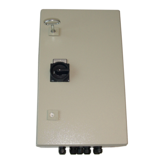
GENERAL VIEW Figure 2 - PWR-240/PWR-480 closed view Main Switch Glands Key Locks Figure 3 – PWR-240/PWR-480 open view 7 Safety Fuse Monophase Switching AC Plug (for temporary use only) Power Supply 5 AC Line Input Terminal Block Cooling Fan... -
Page 6: Guide To Installation
GUIDE TO INSTALLATION The following can be used as a checklist to verify all the steps necessary to complete installation of the PWR power Supply. Before wiring the device make sure the power is disconnected to avoid electrical shock. CAUTION Read all information in the section “Safety Precautions”... -
Page 7: Installation
Before opening the device make sure the power cable is disconnected to avoid electrical shock. CAUTION 1.1 PWR-240/PWR-480 ELECTRICAL DIAGRAM The PWR-240/PWR-480 components are electrically connected as displayed in the following diagram: Two-Pole Fused Disconnecting Switch 10 A Three-Pole Power Switch... -
Page 8: Electrical Connections
PWR-240/PWR-480 1.2 ELECTRICAL CONNECTIONS The PWR-240/PWR-480 power unit provides a terminal block through which AC Line voltage enters and 24 Vdc Low Voltage output is provided. The terminal block also allows various system wiring terminals so that all system wiring (i.e. -
Page 9: Input Line Voltage
Wire according to the following points: Primary wiring: Overcurrent protection should be provided by a 12 to 15 A building installation circuit breaker. Wiring methods from the branch circuit breaker to the PWR-240/ PWR-480 power supply shall comply with the National Electric Code ANSI\NFPA. -
Page 10: Supply Capacity When Wiring Directly To Scanners
24 Vdc + system signals to scanners COM + Figure 7 - Connecting PWR-240/PWR-480 Directly to Scanners Refer to the specific scanner manual to make the connections of the low voltage output and other I/O interface wires to the internal terminal block. -
Page 11: Supply Capacity When Wiring To Sc8000
Only two glands on the power supply unit are utilized, AC Line Input and 24 V DC Output. 24 Vdc AC in Figure 8 - Connecting PWR-240/PWR-480 to SC8000 On the SC8000 Junction Box side, the Low Voltage Output cable must be terminated with the special connector supplied together with the SC8000 (see the SC8000 Installation... -
Page 12: Technical Features
PWR-240/PWR-480 2 TECHNICAL FEATURES ELECTRICAL FEATURES PWR-240 PWR-480 Input Voltage AC from 85 to 264 V from 45-65 Hz Input Current 3.27 A @ 85 V 6.73 A @ 85 V 1.02 A @ 264 V 2.12 A @ 264 V... - Page 13 DECLARATION OF CONFORMITY Datalogic Automation S.r.l. Via S. Vitalino 13 40012 - Lippo di Calderara Bologna - Italy dichiara che declares that the déclare que le bescheinigt, daß das Gerät declare que el PWR-XXX Power Supply Unit e tutti i suoi modelli and all its models et tous ses modèles...