Table of Contents
Advertisement
Quick Links
Advertisement
Table of Contents

Related Manuals for Datalogic PWR-480B


Summary of Contents for Datalogic PWR-480B
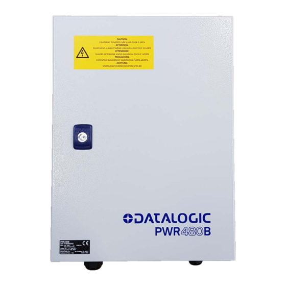
- Page 1 > PWR-480B...
- Page 2 PWR-480B Installation Manual Ed.: 06/2017 © 2016 – 2017 Datalogic S.p.A. and/or its affiliates ALL RIGHTS RESERVED. Without limiting the rights under copyright, no part of this documentation may be reproduced, stored in or introduced into a retrieval system, or transmitted in any form or by any means, or for any purpose, without the express written permission of Datalogic S.p.A.
-
Page 3: Table Of Contents
System Wiring: Test ...................... 1 2 INSTALLATION ......................2 2.1 Cabinet Mounting ......................2 2.2 PWR-480B Electrical Diagram ..................3 2.3 Cable Insertion ......................4 2.3.1 Cable Entry Plate ......................4 2.3.2 AS-I Cable Compression Connectors ................4 3 ELECTRICAL CONNECTIONS ................... 5 ... -
Page 4: Electrical Safety
SAFE ETY REG GULATIO ELECT TRICAL S SAFETY This pro oduct confo orms to the e applicable e requireme ents contain ned in the E European S Standard for elect trical safety y EN 60950- -1 at the da ate of manuf facture. -
Page 5: Ce Compliance
SUPPORT THROUGH THE WEBSITE Datalogic provides several services as well as technical support through its website. Log on to www.datalogic.com and click on the SUPPORT > Unattended Scanning Systems category link. -
Page 6: General View
(for use only during maintenance) AS-I Cable Compression Connectors AC Line Input Terminal Block Cable Entry Plate “DC OK” Terminal Block Monophase Switching Power Supply 24 Vdc Terminal Block Thermal-magnetic circuit breaker Cooling Fan Product Data Label Figure 2 – PWR-480B General View... -
Page 7: Guide To Installation
GUIDE TO INSTALLATION 1 GUIDE TO INSTALLATION The following can be used as a checklist to verify all the steps necessary to complete installation of the PWR power supply. CAUTION: Before opening the device, or performing any installation or maintenance procedures, make sure the external AC disconnecting device is switched OFF. -
Page 8: Installation
PWR-480B INSTALLATION MANUAL 2 INSTALLATION The PWR-480B is an industrial cabinet housing a 24 Vdc power supply which is used to power up a varying number of reading devices (depending on the product), along with their relative accessory devices. See chapter 3 for details. -
Page 9: Pwr-480B Electrical Diagram
INSTALLATION 2.2 PWR-480B ELECTRICAL DIAGRAM The PWR-480B components are electrically connected as displayed in the following diagram: Thermal-magnetic circuit breaker 10 A / 2 poles * AC Socket Monophase Switching 8A max. Power Supply 24 Vdc Figure 3 - PWR-480B Electrical Diagram... -
Page 10: Cable Insertion
2.3.1 Cable Entry Plate Follow these instructions to correctly insert the cables: Determine the number and size of the cables coming into and leaving the PWR-480B. Locate the correct entry hole sizes and positions relative to these cables. Press the cable end through the proper hole so that the gland material seals around it. -
Page 11: Electrical Connections
ELECTRICAL CONNECTIONS 3 ELECTRICAL CONNECTIONS The PWR-480B power unit provides a terminal block through which AC Line voltage enters and 24 Vdc Low Voltage output is provided. Figure 4 – PWR-480B AC Input Power Connections The terminal block also provides two wiring terminals (13-14), which monitor the status of the switching power supply (DC OK feature). -
Page 12: Input Ac Line Voltage
Wire according to the following points: Primary wiring: Overcurrent protection should be provided by a 16 A building installation circuit breaker. Wiring methods from the branch circuit breaker to the PWR-480B power supply shall comply with the National Electric Code ANSI\NFPA. -
Page 13: Laser Barcode Scanners
However all the scanner motors start up slowly so that there is no significant peak current draw. See the specific scanner manual for consumption data. The maximum number of scanners to be supplied for direct wiring by a single PWR-480B is shown in the table below and also depends on the wiring topology:... - Page 14 PWR-480B INSTALLATION MANUAL AS-I Wiring Topologies device PWR- nodes 480B 24 Vdc AS-I single branch with end cap Figure 8 – Single Branch Topology PWR- 480B device nodes 24 Vdc AS-I backbone ring topology Figure 9 - Ring Topology device...
-
Page 15: Supply Capacity When Wiring Directly To Lonworks Scanners
However all the scanner motors start up slowly so that there is no significant peak current draw. See the specific scanner manual for consumption data. The maximum number of scanners to be supplied for direct wiring by a single PWR-480B is shown in the table below:... -
Page 16: Image-Based Id Readers
PWR-480B INSTALLATION MANUAL 3.3 IMAGE-BASED ID READERS 3.3.1 Supply Capacity When Wiring to XRF410N Readers The maximum number of XRF410N modules to be supplied by a single PWR-480B is shown in the following table. XRF410N Model Maximum Number of Modules... - Page 17 24 Vdc CAB-MLP-05 Custom Cable CBL-1480-05 CBX500 ATS-001 CAB-DS05-S P.S. Ethernet Host Figure 13 - Connecting PWR-480B to XRF410N Hi Perf Modules Custom Power Cable to CBX CAB-MLP-0x Cable PWR-480B Wire Color Meaning + 24 Vdc White + 24 Vdc...
-
Page 18: Supply Capacity When Wiring To Matrix 450N Readers
PWR-480B INSTALLATION MANUAL 3.3.2 Supply Capacity When Wiring to Matrix 450N Readers The maximum number of Matrix 450Ns to be supplied by a single PWR-480B is shown in the following table. Maximum Number Readers Matrix 450N The power supply unit can be connected to the Matrix 450N readers according to the... - Page 19 CAB-LD-102 no power cable between the Matrix 450N and its relative LT-03x. Ethernet Host AC in CAB-LP-0x Figure 15 - Connecting PWR-480B to a Matrix 450N ID-NET Multidata Network Custom Power Cable to CBX CAB-LP-0x Cable to LT-03x PWR-480B Wire Color...
-
Page 20: Supply Capacity When Wiring To Ai7000S
NOTE: The AI7000 series illuminators are supplied with a CVL-2389 extension power cable. Use this cable to connect the PWR-480B power supply by cutting off the cable’s male Amphenol connector and connecting the wires to the PWR-480B according to the table below:... -
Page 21: Supply Capacity When Wiring To Nls9000S
AC in PWR-480 to CBX power cable 24 Vdc Figure 17 - Connecting PWR-480B to NLS9000 Illuminator and CBX The NLS9000 series illuminators and CBX9000 connection boxes are supplied with a proper power cord: PWR-480 to CBX Power Cable CAB-502 Cable to NLS9000... -
Page 22: Technical Features
PWR-480B INSTALLATION MANUAL 4 TECHNICAL FEATURES PWR-480B ELECTRICAL FEATURES Input Voltage AC from 100 to 240 V from 50 to 60 Hz Input Current Consumption Max 14 A (Max 6 A for power supply - output at full load) (Max 8 A for internal AC socket) Output Voltage 24 Vdc (adjustable 18-29.5 Vdc)