Table of Contents
Advertisement
Quick Links
Advertisement
Table of Contents

Related Manuals for Datalogic PWR-480B


Summary of Contents for Datalogic PWR-480B
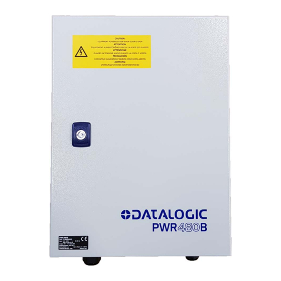
- Page 1 > PWR-480B...
- Page 2 PWR-480B Installation Manual Ed.: 12/2018 © 2014 – 2018 Datalogic S.p.A. and/or its affiliates ALL RIGHTS RESERVED. Without limiting the rights under copyright, no part of this documentation may be reproduced, stored in or introduced into a retrieval system, or transmitted in any form or by any means, or for any purpose, without the express written permission of Datalogic S.p.A.
-
Page 3: Table Of Contents
4.4.3 Supply Capacity When Wiring to AI7000s ..............16 4.4.4 Supply Capacity When Wiring to NLS9000s .............. 17 AC LINE VOLTAGE ELECTRICAL CONNECTIONS ..........18 AC Line Input Voltage ....................18 TECHNICAL FEATURES ................... 19 ELECTRICAL DIAGRAMS ..................20 PWR-480B Electrical Diagram ..................20... -
Page 4: Safety Regulations
SAFETY REGULATIONS ELECTRICAL SAFETY This product conforms to the applicable requirements contained in the following European Standards: EN 61439-1 • EN 60204-1 • EN 60950-1 +A11 +A1 +A12 +A2 • IMPORTANT: This symbol is used to bring the user’s attention to details that are considered IMPORTANT. -
Page 5: Ce Compliance
SUPPORT THROUGH THE WEBSITE Datalogic provides several services as well as technical support through its website. Log on to www.datalogic.com and click on the SUPPORT link which gives you access to: Downloads by selecting your product model from the dropdown list in the Search by •... -
Page 6: General View
AC Input Cable Compression Connector AC Line Input Terminal Block Cable Entry Plate Thermal-magnetic circuit breaker AS-I Cable Compression Connectors “DC OK” Terminal Block 24 Vdc Terminal Block AS-I Cable Sealing Grommets Low Voltage Current Limiting Fuses Figure 2 – PWR-480B General View... -
Page 7: Operating Features
1 OPERATING FEATURES 1.1 DESCRIPTION The PWR-480B is an electrical cabinet housing a 24 Vdc power supply which is used to power up a varying number of reading devices (depending on the product), along with their relative accessory devices. See chapter 4 for details. -
Page 8: Overload Protection
PWR-480B INSTALLATION MANUAL 1.2.2 Overload Protection In the event of sustained output current overloading, overload protection is provided where overload power is supplied as explained in the examples below: Example 1: Up to 120% power overload The overload is supplied for approximately 12 seconds and then is reduced (Voltage and Current) to about 104% power continuously. - Page 9 OPERATING FEATURES Example 2: 125% power overload The overload is supplied for approximately 10 seconds and then is reduced (Voltage and Current) to about 95% power for another 10 seconds. In this case the output voltage falls below 20 Vdc and therefore the power supply shuts down for a recovery time of 17 seconds. This procedure is repeated until the excessive current overload is resolved.
-
Page 10: Pre-Installation Checklist
PWR-480B INSTALLATION MANUAL 2 PRE-INSTALLATION CHECKLIST This chapter can be used as a checklist to verify all the steps necessary to complete installation of the PWR power supply. CAUTION: Opening the cabinet requires a key that should be used by a... -
Page 11: System Wiring: Test
PWR powers up correctly. The green DC-OK light should be on steady and the overload light (red) should off. Close and lock the PWR enclosure and check that it does not open (lock functions correctly). The PWR-480B installation is now complete. -
Page 12: Mechanical Installation
IMPORTANT: The cabinet must be installed vertically in such a way that the key lock is no higher than 1.90 m from the ground (see Fig. 2). Figure 8 – PWR-480B cabinet max. height Please note that the cabinet door can be unlocked and opened by using the key provided... -
Page 13: Low Voltage Electrical Connections
4.1.1 Cable Entry Plate Follow these instructions to correctly insert the cables: Determine the number and size of the cables coming into and leaving the PWR-480B. Locate the correct entry hole sizes and positions relative to these cables. Press the cable end through the proper hole so that the gland material seals around it. -
Page 14: Dc Voltage Terminal Block
DC Outputs protected DC Outputs Figure 10 – PWR-480B DC Output Power Connections 4.2.1 DC OK Monitoring The DC voltage terminal block provides two wiring terminals (13-14), which monitor the status of the switching power supply (DC OK feature). When the power supply module runs correctly, lines 13 and 14 form a normally closed contact. -
Page 15: Laser Barcode Scanners
See the specific scanner manual for consumption data. The maximum number of same type scanners to be supplied for direct wiring by a single PWR-480B is shown in the table below and depends on the wiring topology: PWR-480B Maximum Number of Scanners by Topology... -
Page 16: As-I Wiring Topologies
PWR-480B INSTALLATION MANUAL Refer to the specific scanner manual for I/O interface wiring connections. 4.3.2 AS-I Wiring Topologies 200 W max device PWR- nodes 480B 24 Vdc AS-I single branch with end cap Figure 12 – Single Branch Topology PWR-... -
Page 17: Supply Capacity When Wiring Directly To Lonworks Scanners
However all the scanner motors start up slowly so that there is no significant peak current draw. See the specific scanner manual for consumption data. The maximum number of scanners to be supplied for direct wiring by a single PWR-480B is shown in the table below:... -
Page 18: Image-Based Id Readers
PWR-480B INSTALLATION MANUAL 4.4 IMAGE-BASED ID READERS 4.4.1 Supply Capacity When Wiring to XRF410N Readers The maximum number of XRF410N modules to be supplied by a single PWR-480B is shown in the following table. XRF410N Model Maximum Number of Modules... - Page 19 AC in XRF410N Master Custom Cable CBL-1480-05 CBX500 ATS-001 CAB-DS05-S P.S. Ethernet Host Figure 17 - Connecting PWR-480B to XRF410N Hi Perf Modules Custom Power Cable to CBX CAB-MLP-0x Cable PWR-480B Wire Color Meaning + 24 Vdc White + 24 Vdc...
-
Page 20: Supply Capacity When Wiring To Matrix 450N Readers
PWR-480B INSTALLATION MANUAL 4.4.2 Supply Capacity When Wiring to Matrix 450N Readers The maximum number of Matrix 450Ns to be supplied by a single PWR-480B is shown in the following table. Maximum Number Readers Matrix 450N The power supply unit can be connected to the Matrix 450N readers according to the... - Page 21 CAB-LD-102 no power cable between the Matrix 450N and its relative LT-03x. Ethernet Host AC in CAB-LP-0x Figure 19 - Connecting PWR-480B to a Matrix 450N ID-NET Multidata Network Custom Power Cable to CBX CAB-LP-0x Cable to LT-03x PWR-480B Wire Color...
-
Page 22: Supply Capacity When Wiring To Ai7000S
The AI7000 series illuminators are supplied with a CVL-2389 NOTE: extension power cable. Use this cable to connect the PWR-480B power supply by cutting off the cable’s male Amphenol connector and connecting the wires to the PWR-480B according to the table below:... -
Page 23: Supply Capacity When Wiring To Nls9000S
PWR-480 to CBX 24 Vdc AC in power cable Figure 21 - Connecting PWR-480B to NLS9000 Illuminator and CBX The NLS9000 series illuminators and CBX9000 connection boxes are supplied with a proper power cord: PWR-480 to CBX Power Cable CAB-502 Cable to NLS9000... -
Page 24: Ac Line Voltage Electrical Connections
Primary wiring: Overcurrent protection should be provided by a 16 A building installation circuit breaker. PWR-480B input components are rated for an Icp of 10 kA max. Wiring methods from the branch circuit breaker to the PWR-480B power supply shall comply with the National Electric Code ANSI\NFPA. -
Page 25: Technical Features
TECHNICAL FEATURES 6 TECHNICAL FEATURES PWR-480B ELECTRICAL FEATURES Input Voltage AC from 100 to 240 V from 50 to 60 Hz Input Current Consumption Max 6 A Icp 10kA - output at full load Output Voltage 24 Vdc Nominal Output Current... -
Page 26: Aelectrical Diagrams
PWR-480B INSTALLATION MANUAL ELECTRICAL DIAGRAMS PWR-480B ELECTRICAL DIAGRAM The PWR-480B components are electrically connected as displayed in the following diagram: Figure 23 - PWR-480B Electrical Diagram...