Table of Contents
Advertisement
Quick Links
Advertisement
Table of Contents

Related Manuals for Datalogic PWR-2400


Summary of Contents for Datalogic PWR-2400
- Page 2 PWR-2400 Installation Manual Ed.: 01/2019 © 2016 – 2019 Datalogic S.p.A. and/or its affiliates ALL RIGHTS RESERVED. Without limiting the rights under copyright, no part of this documentation may be reproduced, stored in or introduced into a retrieval system, or transmitted in any form or by any means, or for any purpose, without the express written permission of Datalogic S.p.A.
-
Page 3: Table Of Contents
Cabinet Mounting ......................5 Cable Insertion ......................6 ELECTRICAL CONNECTIONS .................. 7 DC Voltage Terminal Block ..................7 PWR-2400 To AV7000 System Wiring ................ 8 AC LINE INPUT VOLTAGE ..................10 MAINTENANCE ....................... 11 Air Filter Cleaning ..................... 11 Cooling Fan Cleaning....................11 TECHNICAL FEATURES .................. -
Page 4: Safety Regulations
SAFETY REGULATIONS ELECTRICAL SAFETY This product conforms to the applicable requirements contained in the following European Standards: • EN 61439-1 • EN 60204-1 • EN 60950-1 +A11 +A1 +A12 +A2 IMPORTANT: This symbol is used to bring the user’s attention to details that are considered IMPORTANT. -
Page 5: Ce Compliance
SUPPORT THROUGH THE WEBSITE Datalogic provides several services as well as technical support through its website. Log on to www.datalogic.com and click on the SUPPORT link which gives you access to: •... -
Page 6: General View
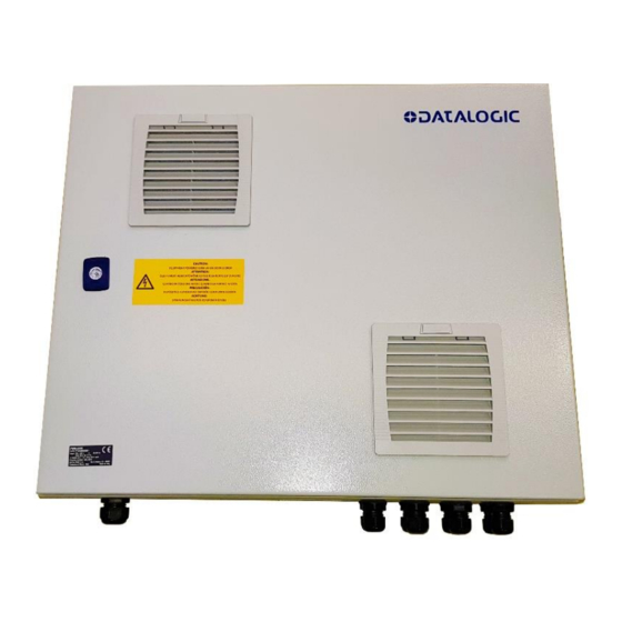
Filtered Air Intake 24 Vdc Terminal Block Filtered Cooling Fan Out 4A Miniature circuit breaker AC Line Input Compression Connector Cooling Fan DC Output Compression Connectors Monophase Switching Power Supplies AC Line Input Terminal Block Figure 2 – PWR-2400 General View... -
Page 7: Operating Features
1 OPERATING FEATURES 1.1 DESCRIPTION The PWR-2400 is an electrical cabinet housing five 24 Vdc power supply units used to power up a varying number of reading devices (depending on the product), along with their relative accessory devices. See chapter 4 for details. -
Page 8: Overload Protection
PWR-2400 INSTALLATION MANUAL 1.2.2 Overload Protection In the event of sustained output current overloading, overload protection is provided where overload power is supplied as explained in the examples below: Example 1: Up to 120% power overload The overload is supplied for approximately 12 seconds and then is reduced (Voltage and Current) to about 104% power continuously. - Page 9 OPERATING FEATURES Example 2: 125% power overload The overload is supplied for approximately 10 seconds and then is reduced (Voltage and Current) to about 95% power for another 10 seconds. In this case the output voltage falls below 20 Vdc and therefore the power supply shuts down for a recovery time of 17 seconds. This procedure is repeated until the excessive current overload is resolved.
-
Page 10: Pre-Installation Checklist
The green DC-OK lights should be on steady and the overload lights (red) should be off. Close and lock the PWR enclosure and check that it does not open (lock functions correctly). The PWR-2400 installation is now complete. -
Page 11: Mechanical Installation
IMPORTANT: The cabinet must be installed vertically in such a way that the key lock is no higher than 1.90 m from the ground (see Figure 8). Figure 8 – PWR-2400 cabinet max. height Please note that the cabinet door can be unlocked and opened by using the key provided... -
Page 12: Cable Insertion
PWR-2400 INSTALLATION MANUAL 3.2 CABLE INSERTION The PWR-2400 is provided with an AC Line Input Compression Connector and eight DC Output Compression Connectors, as shown in Figure 9. Prepare each cable by stripping the wires and inserting the compression connector nut. -
Page 13: Electrical Connections
4.1 DC VOLTAGE TERMINAL BLOCK 4 A MCB DC OK signals protected DC DC Outputs Outputs Figure 10 - PWR-2400 DC Output Power Connections If the 93ACC0084 Air Cleaning System is used, make sure to power it through the F51 protected block. -
Page 14: Pwr-2400 To Av7000 System Wiring
PWR-2400 INSTALLATION MANUAL 4.2 PWR-2400 TO AV7000 SYSTEM WIRING A single PWR-2400 supports up to five AV7000 cameras in a multi-sided reading station application. The power supply unit is connected to the camera illuminators according to the following diagram (power supply side): See also the AV7000 Reference Manual or your application specific drawings for more details. - Page 15 ELECTRICAL CONNECTIONS NOTE: The AI7000 series illuminators are supplied with a CVL-2389 extension power cable. Use this cable to connect the PWR-2400 power supply by cutting off the cable’s male Amphenol connector and connecting the wires to the PWR-2400 according to the table below:...
-
Page 16: Ac Line Input Voltage
Primary wiring: Overcurrent protection should be provided by a 32 A building installation circuit breaker. PWR-2400 input components are rated for an Icp of 10 kA max. Wiring methods from the branch circuit breaker to the PWR-2400 power supply shall comply with the National Electric Code ANSI\NFPA. -
Page 17: Maintenance
MAINTENANCE 6 MAINTENANCE 6.1 AIR FILTER CLEANING Air filters should be cleaned on a regular maintenance schedule between once every month and once every three months depending on the environment in which the power supply is installed. To clean the air filters: 1. -
Page 18: Technical Features
PWR-2400 INSTALLATION MANUAL 7 TECHNICAL FEATURES PWR-2400 ELECTRICAL FEATURES Input Voltage AC from 100 to 240 V from 50 to 60 Hz Input Current Consumption Max 30 A Icp 10kA - output at full load Output Voltage 24 Vdc for each power module... -
Page 19: Aelectrical Diagrams
ELECTRICAL DIAGRAMS ELECTRICAL DIAGRAMS PWR-2400 ELECTRICAL DIAGRAM The PWR-2400 components are electrically connected as displayed in the following diagram: Figure 13 - PWR-2400 Electrical Diagram...