
Related Manuals for Telit Wireless Solutions SL869-V3


Summary of Contents for Telit Wireless Solutions SL869-V3
- Page 1 SL869-V3 Product User Guide 1VV0301217 Rev. 6 – 2021-03-31 Telit Technical Documentation...
-
Page 2: Applicability Table
SL869-V3 Product User Guide APPLICABILITY TABLE PRODUCTS SL869-V3 1VV0301217 Rev. 6 Page 2 of 62 2021-03-31... -
Page 3: Table Of Contents
SL869-V3 Product User Guide CONTENTS APPLICABILITY TABLE CONTENTS INTRODUCTION 1.1. Scope 1.2. Audience 1.3. Contact Information, Support 1.4. Symbol Conventions 1.5. Related Documents PRODUCT DESCRIPTION 2.1. Product Overview 2.2. Block Diagram 2.3. Module Photo EVALUATION KIT (EVK) PRODUCT FEATURES 4.1. - Page 4 SL869-V3 Product User Guide 4.12. Antenna Sense 4.13. Serial I/O Ports 4.13.1. UART 4.13.2. PRODUCT PERFORMANCE 5.1. Horizontal Position Accuracy 5.2. Time to First Fix 5.3. Sensitivity MESSAGE INTERFACE 6.1. NMEA Output Messages 6.1.1. NMEA Standard Messages 6.1.2. Proprietary Messages 6.2.
- Page 5 9.10. Powering an External LNA (active antenna) REFERENCE DESIGNS 10.1. SL869-V3 Reference Design 10.2. SL869-V3 Reference Design with Antenna Enable and Antenna Sense 40 MECHANICAL DRAWING PCB FOOTPRINT PRODUCT PACKAGING AND HANDLING 13.1. Product Marking and Serialization 1VV0301217 Rev. 6...
- Page 6 SL869-V3 Product User Guide 13.2. Product Packaging 13.3. Moisture Sensitivity 13.4. ESD Sensitivity 13.5. Reflow 13.6. Assembly Considerations 13.7. Washing Considerations 13.8. Safety 13.9. Disposal ENVIRONMENTAL REQUIREMENTS 14.1. Operating Environmental Limits 14.2. Storage Environmental Limits COMPLIANCES 15.1. ISO 9000 Accredited 15.2.
- Page 7 SL869-V3 Product User Guide DOCUMENT HISTORY 1VV0301217 Rev. 6 Page 7 of 62 2021-03-31...
-
Page 8: Introduction
SL869-V3 Product User Guide 1. INTRODUCTION 1.1. Scope This document provides product information for the SL869-V3 GNSS module. 1.2. Audience This document is intended for Telit customers, especially system integrators, about to implement their applications using the SL869-V3 GNSS module. -
Page 9: Symbol Conventions
1.5. Related Documents • SL869-V3 Data Sheet (Not Subjected to NDA) • SL869-V3 Evaluation Kit User Guide (Not Subjected to NDA) • V33 Software User Guide (Not Subjected to NDA) • ST Antenna Sense App Note • V33 Software Authorized User Guide 1VV0301217 Rev. -
Page 10: Product Description
SL869-V3 Product User Guide 2. PRODUCT DESCRIPTION The SL869-V3 is a 12.2mm x 16.0 mm x 2.55 mm fully integrated GNSS module which includes an ST Micro Teseo III GNSS engine with an ARM-9 core processor, flash memory, TCXO, RTC, LNA and SAW filter. -
Page 11: Block Diagram
24-pad 16.0 x 12.2 x 2.4 mm Industry Standard LCC castellated edge package • eCall and ERA/GLONASS compliant RED and RoHS compliant design • 2.2. Block Diagram Figure 2-1 SL869-V3 Block Diagram 1VV0301217 Rev. 6 Page 11 of 62 2021-03-31... -
Page 12: Module Photo
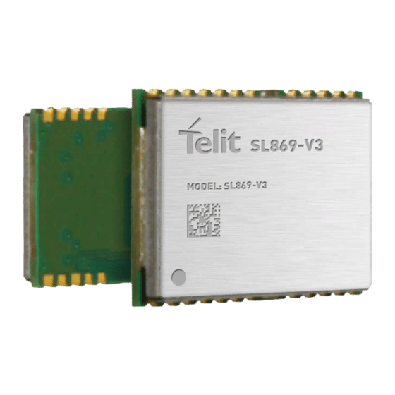
SL869-V3 Product User Guide 2.3. Module Photo Figure 2-2 SL869-V3 Module Photo 1VV0301217 Rev. 6 Page 12 of 62 2021-03-31... -
Page 13: Evaluation Kit (Evk)
SL869-V3 Product User Guide 3. EVALUATION KIT (EVK) The Evaluation Kit (EVK) contains the necessary hardware, software, and documentation to assist the customer in evaluating the module for inclusion in a design. Figure 3-1 Evaluation Kit (EVK) Contents 1VV0301217 Rev. 6... -
Page 14: Product Features
SL869-V3 Product User Guide 4. PRODUCT FEATURES 4.1. Multi-Constellation Navigation GPS and GLONASS constellations are enabled by default. The user may enable or disable GPS, GLONASS, Galileo, and BDS constellations via command. GLONASS and BeiDou cannot be enabled simultaneously. 4.2. -
Page 15: Locally Generated Agps (St-Agps)
SL869-V3 Product User Guide ephemeris or BE) every 30 seconds. This is therefore the minimum time required for a cold start Time to First Fix (TTFF). The BE data is usually refreshed every 2 hours. The minimum cold start TTFF can be reduced from 30 seconds to just a few seconds by enabling AGPS, which can provide Extended Ephemeris (EE) data by two methods - •... -
Page 16: Differential Gps (Dgps)
SL869-V3 Product User Guide 4.5. Differential GPS (DGPS) Differential corrections can be supplied to the module from an RTCM beacon receiver. RTCM SC-104 Ver. 2.3 messages 1, 9 and 31 (both GPS and GLONASS) are supported. The module will indicate Differential mode when corrections are supplied. -
Page 17: 1Pps
SL869-V3 Product User Guide 4.10. 1PPS The module provides a 1PPS output signal whenever the receiver has a valid fix (2D or 3D). The pulse is approx. 500 ms 4.11. Antenna Enable The Antenna Enable output can be used to control an external power supply to an active antenna (or external LNA). -
Page 18: Product Performance
Glonass Warm Cold BeiDou Warm Cold GPS + GLO Warm Cold GPS + BeiDou Warm Cold Test Conditions: Static scenario, -130 dBm, Full Power mode Table 5-2 SL869-V3 Time To First Fix 1VV0301217 Rev. 6 Page 18 of 62 2021-03-31... -
Page 19: Sensitivity
SL869-V3 Product User Guide 5.3. Sensitivity Constellation(s) State Minimum Signal Level (dBm) Acquisition -148 Navigation -162 Tracking -162 Acquisition -146 GLONASS Navigation -159 Tracking -161 Acquisition -147 BeiDou Navigation -154 Tracking -161 Test Conditions: Static Scenario, Full Power mode Table 5-3 SL869-V3 Sensitivity 1VV0301217 Rev. -
Page 20: Message Interface
SL869-V3 Product User Guide 6. MESSAGE INTERFACE The primary UART port (TX/RX) supports full duplex communication between the receiver and the user. Its default function is NMEA output data and input commands. The default UART configuration is: 9600 bps, 8 data bits, no parity, and 1 stop bit. -
Page 21: Proprietary Messages
SL869-V3 Product User Guide NMEA Talker IDs used are: Talker ID Constellation Galileo BeiDou GLONASS QZSS Solutions using multiple constellations Table 6-3 NMEA Talker IDs 6.1.2. Proprietary Messages The receiver can issue several proprietary NMEA output messages ($PSTM) which report additional receiver data and status information. -
Page 22: Flash Upgradability
SL869-V3 Product User Guide 7. FLASH UPGRADABILITY The firmware stored in the internal flash memory of the module may be upgraded via the main serial port (TX/RX). During normal operation, the BOOT pin should be left floating. This will ensure that the module executes code from its internal flash memory. -
Page 23: Electrical Interface
SL869-V3 Product User Guide 8. ELECTRICAL INTERFACE 8.1. SL869-V3 Pin-out Diagram Figure 8-1 SL869-V3 Pin-out Diagram 1VV0301217 Rev. 6 Page 23 of 62 2021-03-31... -
Page 24: Sl869-V3 Pin-Out Table
Main 3.3 V Supply Voltage Ground Note: All GND pins must be connected to ground Note: Pins 3, 14, and 20 must be LOW when power is applied (for normal operation) Table 8-1 SL869-V3 Pin-out Table 1VV0301217 Rev. 6 Page 24 of 62 2021-03-31... -
Page 25: Dc Characteristics
SL869-V3 Product User Guide 8.3. DC Characteristics Signal Description Units Low level output voltage, IOL 2mA High level output voltage, IOH 2mA 0.75*VDD Low level input voltage -0.3 0.45 High level input voltage, IIH 2mA 0.7*VDD Internal pull-up resistor equivalent kΩ... -
Page 26: Vbatt
SL869-V3 Product User Guide The supply voltage must be within specification within 10 milliseconds of initial application. The power-up sequence must not be interrupted during the first second or the module may fail to start up. If the module does not initialize correctly due to improper application of VCC, the module can be reset by: •... -
Page 27: Dc Power Consumption
SL869-V3 Product User Guide 8.5.4. DC Power Consumption State & Constellation Units Acquisition GPS Only GPS + Glonass GPS + BeiDou Navigation/Tracking GPS Only GPS + Glonass GPS + BeiDou Standby (Vbatt) Operating temperature: 25°C. Supply voltage: 3.3 VDC nominal Table 8-5 Power Consumption 8.6. -
Page 28: 1Pps
SL869-V3 Product User Guide 8.6.4. 1PPS 1PPS is a one pulse per second signal which is enabled after the receiver has achieved a 2D or 3D position fix. It is disabled if the position fix is lost. The pulse is approximately 50% duty cycle. -
Page 29: Uart0 (Tx/Rx): Pins 20 And
SL869-V3 Product User Guide Warning: Care must be used to prevent backdriving the RX line(s) when the module is powered down or in a low-power state. If the RX signal is used, it is important that it be either high impedance or logic low whenever VCC has been removed from the device. -
Page 30: Rf Interface
SL869-V3 Product User Guide Warning: I2C and UART cannot be used at the same time. Note/Tip: Contact Telit Technical Support for any further information regarding I2C configuration. 8.9. RF Interface 8.9.1. RF IN The RF input (RF-IN) pin accepts GNSS L1 band signals from the GPS, GLONASS, BeiDou, Galileo, and QZSS constellations at a level between -125 dBm and -165 dBm into 50 Ω... -
Page 31: Burnout Protection
SL869-V3 Product User Guide 8.9.2. Burnout Protection The receiver accepts without risk of damage a signal of +10 dBm from 0 to 2 GHz carrier frequency, except in band 1560 to 1610 MHz where the maximum level is -10 dBm. -
Page 32: Rf Front End Design
SL869-V3 Product User Guide 9. RF FRONT END DESIGN 9.1. RF Signal Requirements The receiver can achieve Cold Start acquisition with a signal level above the specified minimum at its input. This means that it can acquire and track visible satellites, download the necessary ephemeris data and compute the location within a 5-minute period. -
Page 33: Gnss Antenna Polarization
SL869-V3 Product User Guide • GNSS satellite elevation angle • Free space path loss • Extraneous path loss (such as rain) • Partial or total path blockage (such as foliage or buildings) • Multipath interference (caused by signal reflection) •... -
Page 34: Active Versus Passive Antenna
SL869-V3 Product User Guide An RHCP antenna will have 3 dB gain compared to a linearly polarized antenna (assuming the same antenna gain specified in dBic and dBi respectively). An RHCP antenna is better at rejecting multipath interference than a linearly polarized antenna because the reflected signal changes polarization to LHCP. -
Page 35: System Noise Floor
SL869-V3 Product User Guide An antenna vendor should specify a nominal antenna gain (usually at zenith, or directly overhead) and antenna pattern curves specifying gain as a function of elevation, and gain at a fixed elevation as a function of azimuth. Pay careful attention to the requirement to meet the required design, such as ground plane size and any external matching components. -
Page 36: Pcb Stack And Trace Impedance
SL869-V3 Product User Guide However, if a good quality external LNA is used, the noise figure of that LNA (typically better than 1dB) could reduce the overall system noise figure from 4 dB to approximately 2 dB. 9.6. PCB stack and Trace Impedance It is important to maintain a 50 Ω... -
Page 37: Rf Interference
SL869-V3 Product User Guide 9.8. RF Interference RF interference into the GNSS receiver tends to be the biggest problem when determining why the system performance is not meeting expectations. As mentioned earlier, the GNSS signals are at a level of -130 dBm and lower. If signals higher than this are presented to the receiver, the RF front end can be overdriven. - Page 38 SL869-V3 Product User Guide one end of the stub to appear as an RF open at the other end. The RF short is created by a high quality RF capacitor operating at self-resonance. The choice between the two would be determined by: •...
-
Page 39: Reference Designs
10. REFERENCE DESIGNS 10.1. SL869-V3 Reference Design Figure 10-1 SL869-V3 Reference Design Along with power and ground, the minimum signals required to operate the module properly are described below. The power supply must have tight voltage regulation under varying line and load conditions to prevent falsely tripping the internal voltage supervisor within the module. -
Page 40: Sl869-V3 Reference Design With Antenna Enable And Antenna Sense
SL869-V3 Product User Guide 10.2. SL869-V3 Reference Design with Antenna Enable and Antenna Sense The Antenna Sense pins provide the capability for the module to check the antenna current draw and report its status as NORMAL, SHORT, or OPEN. This status is reported at startup and whenever the status changes. -
Page 41: Mechanical Drawing
SL869-V3 Product User Guide 11. MECHANICAL DRAWING Figure 11-1 SL869-V3 Mechanical Drawing Figure 11-2 3-D Mechanical Drawing 1VV0301217 Rev. 6 Page 41 of 62 2021-03-31... -
Page 42: Pcb Footprint
SL869-V3 Product User Guide 12. PCB FOOTPRINT The module uses advanced packaging with a base metal of copper and an Electroless Nickel Immersion Gold (ENIG) finish. Figure 12-1 SL869-V3 PCB Footprint 1VV0301217 Rev. 6 Page 42 of 62 2021-03-31... -
Page 43: Product Packaging And Handling
SL869-V3 Product User Guide 13. PRODUCT PACKAGING AND HANDLING 13.1. Product Marking and Serialization The module label has a 2D Barcode identifying the module and its serial number. Contact a Telit representative for information on specific module serial numbers. Figure 13-1 Product Label... - Page 44 SL869-V3 Product User Guide All packaging is ESD protective lined. Figure 13-2 Tape and Reel Packaging Figure 13-3 Tape and Reel – Tape detail 1VV0301217 Rev. 6 Page 44 of 62 2021-03-31...
-
Page 45: Moisture Sensitivity
SL869-V3 Product User Guide Figure 13-4 Tray Packaging 13.3. Moisture Sensitivity Precautionary measures are required in handling, storing and using these devices to avoid damage from moisture absorption. If localized heating is required to rework or repair the device, precautionary methods are required to avoid exposure to solder reflow temperatures that can result in performance degradation. - Page 46 SL869-V3 Product User Guide hermetic seal provided the factory conditions are less than 30°C and less than 60% and the humidity indicator card indicates less than 10% relative humidity. If the package has been opened or the humidity indicator card indicates above 10%, then the parts must be baked prior to reflow.
- Page 47 SL869-V3 Product User Guide Figure 13-5 Moisture-Sensitive Device Label 1VV0301217 Rev. 6 Page 47 of 62 2021-03-31...
-
Page 48: Esd Sensitivity
SL869-V3 Product User Guide 13.4. ESD Sensitivity The module contains class 1 devices and is classified as Electro-Static Discharge Sensitive (ESDS). Telit recommends the two basic principles of protecting ESD devices from damage: • Handle sensitive components only in an ESD Protected Area (EPA) under protected and controlled conditions;... -
Page 49: Safety
SL869-V3 Product User Guide cleaning equipment, the drying cycle may not be sufficient to thoroughly dry the module, so additional steps may need to be taken. Exact process details will need to be determined by the type of washing equipment as well as other components on the board to which the module is attached. -
Page 50: Environmental Requirements
SL869-V3 Product User Guide 14. ENVIRONMENTAL REQUIREMENTS 14.1. Operating Environmental Limits Operating Limits Temperature -40°C to +85°C Temperature ±1°C / minute maximum Rate of Change Up to 95% non-condensing or a wet bulb temperature of +35°C, whichever is Humidity less... -
Page 51: Compliances
SL869-V3 Product User Guide 15. COMPLIANCES 15.1. ISO 9000 Accredited Manufactured in an ISO 9000: 2008 accredited facility 15.2. RoHS Compliance Manufactured in compliance with Directive 2011/65/EU art. 16 on the restriction of the use of certain hazardous substances in electrical and electronic equipment (RoHS) 15.3. -
Page 52: Red Declaration Of Conformity
SL869-V3 Product User Guide 15.6. RED Declaration of Conformity Figure 15-1 EU RED Declaration of Conformity 1VV0301217 Rev. 6 Page 52 of 62 2021-03-31... -
Page 53: Product And Safety Information
SL869-V3 Product User Guide 16. PRODUCT AND SAFETY INFORMATION 16.1. Copyrights and Other Notices SPECIFICATIONS ARE SUBJECT TO CHANGE WITHOUT NOTICE Although reasonable efforts have been made to ensure the accuracy of this document, Telit assumes no liability resulting from any inaccuracies or omissions in this document, or from the use of the information contained herein. -
Page 54: Usage And Disclosure Restrictions
SL869-V3 Product User Guide computer programs, including – but not limited to - the exclusive right to copy or reproduce in any form the copyrighted products. Accordingly, any copyrighted computer programs contained in Telit’s products described in this instruction manual shall not be copied (reverse engineered) or reproduced in any manner without the express written permission of the copyright owner, being Telit or the Third Party software supplier. -
Page 55: Trademarks
SL869-V3 Product User Guide 16.2.4. Trademarks TELIT and the Stylized T-Logo are registered in the Trademark Office. All other product or service names are property of their respective owners. 16.2.5. Third Party Rights The software may include Third Party’s software Rights. In this case the user agrees to comply with all terms and conditions imposed in respect of such separate software rights. -
Page 56: Safety Recommendations
SL869-V3 Product User Guide 16.3. Safety Recommendations Make sure the use of this product is allowed in your country and in the environment required. The use of this product may be dangerous and has to be avoided in areas where: •... -
Page 57: Glossary
SL869-V3 Product User Guide 17. GLOSSARY Assisted (or Aided) GPS AGPS provides ephemeris data to the receiver to allow faster cold start times than would be possible using only broadcast data. AGPS This extended ephemeris data could be either server-generated or locally-generated. - Page 58 SL869-V3 Product User Guide A factor used to describe the effect of satellite geometry on the accuracy of the time and position solution of a GNSS receiver. A lower value of GDOP indicates a smaller error in the solution. Related factors include PDOP, HDOP, VDOP and TDOP.
- Page 59 SL869-V3 Product User Guide A receiver, while in normal operation, loses RF signal (perhaps due to the antenna cable being disconnected or a vehicle entering Reacquisition a tunnel), and re-establishes a valid fix after the signal is restored. Contrast with Reset and Restart.
- Page 60 SL869-V3 Product User Guide Universal Asynchronous Receiver/Transmitter UART An integrated circuit (or part thereof) which provides a serial communication port for a computer or peripheral device. Wide Area Augmentation System WAAS The North American SBAS system developed by the US FAA (Federal Aviation Administration).
- Page 61 SL869-V3 Product User Guide 18. DOCUMENT HISTORY Revision Date Changes Updated paragraph 8.8.2 – I2C Port Operation 2021-03-31 Updated paragraph 14.1. – Operating Environmental Limits Added EU RED DoC 2018-08-20 Corrected minor typos and formatting. updated sensitivity values in compliance with new FW...
Need help?
Do you have a question about the SL869-V3 and is the answer not in the manual?
Questions and answers