Campbell Irgason Product Manual
Integrated co2/h2o open-path gas analyzer and 3d sonic anemometer
Hide thumbs
Also See for Irgason:
- Instruction manual (56 pages) ,
- Quick using manual (12 pages) ,
- Product manual (82 pages)

Subscribe to Our Youtube Channel
Related Manuals for Campbell Irgason


Summary of Contents for Campbell Irgason
- Page 1 Product Manual Revision: 08/2021 Copyright © 2010 – 2021 Campbell Scientific, Inc.
-
Page 2: Table Of Contents
Table of contents 1. Introduction 2. Precautions 3. Initial inspection 4. Overview 5. Specifications 5.1 Measurements 5.2 Output signals 5.3 Physical description 5.4 Power requirements during power up and operation 6. Installation 6.1 Orientation 6.2 Mounting 6.3 Wiring and connections 7. - Page 3 10.3 EC100Configure() instruction 10.3.1 ConfigCmd 11 zero-and-span control 10.3.2 ConfigCmd 18 heater voltage 10.4 Example CRBasic program 11. Theory of operation 11.1 IRGASON sonic anemometer 11.1.1 Wind speed 11.1.2 Temperature 11.2 IRGASON gas analyzer 12. References Appendix A. Filter bandwidth and time delay Appendix B.
- Page 4 Appendix C. Equations Appendix D. Safety data sheets (SDS) D.1 Molecular sieve, Type 13X D.2 Magnesium perchlorate D.3 Decarbite Appendix E. IRGASON packing information Table of Contents - iii...
-
Page 5: Introduction
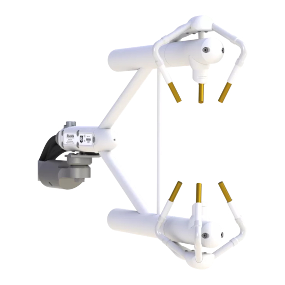
1. Introduction The IRGASON, U.S. Des. Patent No. D680455, is an in situ, open-path, mid-infrared absorption gas analyzer integrated with a three-dimensional sonic anemometer. The gas analyzer provides measurements of absolute densities of carbon dioxide and water vapor, while the sonic anemometer measures orthogonal wind components. -
Page 6: Initial Inspection
WARNING: Do not carry the IRGASON by the arms or the strut between the arms. Always hold it by the block, where the upper and lower arms connect. Handle the IRGASON carefully. The optical source may be damaged by rough handling, especially while the analyzer is powered. -
Page 7: Specifications
The IRGASON is measured and controlled by the EC100 electronics, which synchronizes gas and wind data, essential for valid flux calculations using the eddy-covariance method. The EC100 electronics also uses inputs from an included temperature thermistor probe and a barometer. - Page 8 ±0.55 mgCO ·m ·°C (±0.3 μmolCO ·mol·°C –1 –1 Gain Drift: ±0.1% of reading·µmolCO ·mol °C (maximum) –1 Sensitivity to H ±1.1 x 10⁻⁴ µmolCO ·mol mmolH O (max) IRGASON® Integrated CO O Open-Path Gas Analyzer and 3D Sonic Anemometer...
- Page 9 Basic barometer Accuracy –30 to 0 °C: ±3.7 kPa at –30 °C, falling linearly to ±1.5 kPa at 0 °C 0 to 50 °C: ±1.5 kPa Measurement rate: 10 Hz IRGASON® Integrated CO O Open-Path Gas Analyzer and 3D Sonic Anemometer...
-
Page 10: Output Signals
Optional enhanced barometer Manufacturer: Vaisala Model: PTB110 Accuracy –30 to 0 °C: ±0.15 kPa Measurement rate: 1 Hz IRGASON temperature sensor Manufacturer: BetaTherm Model: 100K6A1A Thermistor Accuracy: ±0.15 °C (–30 to 50 °C) user selectable noise rms, assumes: 25 °C 85 kPa –3... - Page 11 –3 Full scale range: – 2 to 41 g·m user selectable Synchronous Device for Measurement. A Campbell Scientific, Inc. proprietary serial interface for data logger to peripheral and sensor communication. See SDM output (p. 27) for details. IRGASON® Integrated CO...
-
Page 12: Physical Description
Cable Length: 3 m (9.8 ft) EC100 Enclosure: 24.1 x 35.6 x 14 cm (9.5 x 14.0 x 5.5 in) Weight IRGASON with cable: 2.8 kg (6.1 lbs) EC100 with enclosure: 3.2 kg (7.1 lbs) Designed EC100 ingress protection IP65... - Page 13 FIGURE 5-1. IRGASON dimensions, side view IRGASON® Integrated CO O Open-Path Gas Analyzer and 3D Sonic Anemometer...
- Page 14 FIGURE 5-2. IRGASON dimensions, front view IRGASON® Integrated CO O Open-Path Gas Analyzer and 3D Sonic Anemometer...
-
Page 15: Power Requirements During Power Up And Operation
(source) of the gas analyzer directly above the lower arm (detector). If the IRGASON is to be used in a marine environment, or in an environment where it is exposed to corrosive chemicals (for example, the sulfur-containing compounds in viticulture), attempt to mount the IRGASON in a way that reduces the exposure of the sonic transducers to saltwater or corrosive chemicals. -
Page 16: Mounting
WARNING: Do not carry the IRGASON by the arms or the strut between the arms. Always hold it by the block, where the upper and lower arms connect. 3. Bolt the IRGASON mounting bracket to the CM250 leveling mount (see FIGURE 6-1 (p. - Page 17 (it should slide into place and be able to securely hang from the bracket), and tightening the bolts (see FIGURE (p. 14)). FIGURE 6-1. Exploded view of mounting the IRGASON WARNING: Overtightening bolts will damage or deform the mounting hardware. IRGASON® Integrated CO...
- Page 18 FIGURE 6-2. EC100-enclosure mounting bracket mounted on a vertical mast (left) and a tripod leg (right) FIGURE 6-3. Exploded view of mounting the EC100 enclosure IRGASON® Integrated CO O Open-Path Gas Analyzer and 3D Sonic Anemometer...
-
Page 19: Wiring And Connections
EC100 enclosure, and sensor connections to the EC100, respectively. Refer to these figures during wiring and connecting. 1. Find the thicker black cable coming from the block of the IRGASON. This is the IRGASON gas-analyzer cable. Connect this cable to the EC100 electronics by removing the EC100 IRGASON®... - Page 20 (p. 16)). The gas analyzer cable is approximately 3 m (9.8 ft) in length. 3. Connect the IRGASON sonic cable. Similar to (a), begin by removing the black rubber cable entry plug found on the bottom left of the EC100 enclosure. Insert the cable entry plug on...
- Page 21 FIGURE 6-6. Base of EC100 enclosure NOTE: Unique calibration information is stored in the gas and sonic connectors of the IRGASON rather than in the EC100. This means that any IRGASON may be used with any EC100. FIGURE 6-7. Sensor connections to EC100 IRGASON®...
- Page 22 The IRGASON temperature probe cable is approximately 3 m (9.8 ft) in length. 5. Ground the EC100 by attaching a thick wire (for example, 12 AWG) to the grounding lug found on the base of the EC100 enclosure.
-
Page 23: Settings
12V and ground, respectively. 8. Connect the power cable to a power source. The power and ground ends may be wired to the 12V and G ports, respectively, of a Campbell Scientific data logger or to another 12 VDC source. -
Page 24: Factory Defaults
Temperature Sensor Auto-Select (IRGASON Temp Sensor) Pressure Sensor EC100 Basic or EC100 Enhanced (depending on order) Pressure Differential Enable Auto-Select (Disabled for IRGASON) Heater Control Disabled 7.2 Bandwidth The EC100 has a user-selectable low-pass filter to select the bandwidth (5, 10, 12.5, or 20 Hz). -
Page 25: Sdm Address
SDM output. Each SDM device on the SDM bus must have a unique address. The IRGASON has a factory default SDM address of 1, but it may be changed to any integer value between 0 and 14. The value 15 is reserved as an SDM-group trigger. -
Page 26: Temperature Sensor
7.10 Fixed temperature value If the Temperature Sensor setting is None, the IRGASON will use the value of this setting for the sample temperature. This mode is intended for troubleshooting only. In normal operation, Temperature Sensor is set to Auto-Select, and this setting is not used. -
Page 27: Fixed Pressure Value
This setting should remain disabled. It is used only for closed-path analyzers. 7.13 Heater control An advantage of the IRGASON’s low power consumption (5 W) is that the instrument remains at a temperature very close to ambient air temperature, which is an important feature for eddy- covariance measurements. -
Page 28: Ecmon
EC100Configure() instruction (p. 49). 7.14 ECMon Settings for the IRGASON are easily verified or changed using the Windows PC support software ECMon (Eddy Covariance Monitor), which is found at www.campbellsci.com/downloads Launch ECMon, and connect the EC100 electronics to the PC with the included EC100 USB cable. - Page 29 FIGURE 7-1. Main window of ECMon software IRGASON® Integrated CO O Open-Path Gas Analyzer and 3D Sonic Anemometer...
-
Page 30: Device Configuration Utility
7.15 Device Configuration Utility Device Configuration Utility software may also be used to change settings, although ECMon is generally preferred because of its more user-friendly interface. Device Configuration Utility may be downloaded from the Campbell Scientific website www.campbellsci.com ). Device Configuration Utility requires a USB driver to communicate with the EC100, similar to ECMon. -
Page 31: Ec100 Outputs
See the CR6 manual for more details. Each SDM device on the SDM bus must have a unique address. The IRGASON has a factory default SDM address of 1, but may be changed to any integer value between 0 and 14 (see address (p. -
Page 32: Usb Or Rs-485 Output
USB or RS-485, may be selected at a given time. RS-485 output is recommended if cable lengths exceed 100 meters. If a Campbell Scientific data logger is not being used to collect the data from the IRGASON, either unprompted mode is recommended. - Page 33 The computed signature and the transmitted signature are compared. If they match, the data were received correctly. This is very similar to a cyclic redundancy check (CRC). IRGASON® Integrated CO O Open-Path Gas Analyzer and 3D Sonic Anemometer...
-
Page 34: Analog Outputs
If signatures do not match, the data should be disregarded. Following is an example implementation of Campbell Scientific’s signature algorithm in the programming language C. To generate the signature of an output array of bytes, the “seed”... -
Page 35: Maintenance
Check the humidity indicator card in the EC100 enclosure. If the highest dot has turned pink, replace or recharge the desiccant bags. Replacement desiccant may be purchased from Campbell Scientific or obtained elsewhere. See the manual ENC10/12, ENC12/14, ENC14/16, ENC16/18, available at www.campbellsci.com... -
Page 36: Wick Maintenance
Once the water droplets evaporate or are removed, the IRGASON will again measure wind. Remove the water droplets by dabbing a cotton swab or tissue on the faces of the transducers. The user must use discretion to determine if wicks are necessary. -
Page 37: Gas Analyzer Wicks
FIGURE 9-2. Spare Sonic Wicks Kit contents 9.2.2 Gas analyzer wicks IRGASON gas analyzer windows are polished and slanted at an angle to prevent water from collecting on their surfaces. However, due to increased surface tension at the interface with the snout, water can pool at the edges and partially block the optical path and attenuate the signal. -
Page 38: Gas Analyzer Window Cleaning
1.0. 9.4 Zero and span As is the case with all optical instruments, the IRGASON gas analyzer measurements may drift slightly with exposure to natural elements. Therefore, routine maintenance requires a periodic zero-and-span procedure. The frequency with which this should be done is heavily dependent IRGASON®... - Page 39 A regimented protocol for zero and span of the instrument initially, will allow the user to assess the appropriate time interval between zero-and-span procedures. However, if the IRGASON is being used at a site with large seasonal changes in ambient conditions, the zero-and-span procedure should be done at least seasonally.
- Page 40 To check and then set the IRGASON zero and span, follow the steps below: 1. Remove power from the EC100. 2. If not already done, clean the windows and snouts with alcohol and a non-scratching tissue or cloth. CAUTION: Make sure the alcohol and any residual water completely evaporate from the analyzer before proceeding with the zero-and-span procedure.
- Page 41 4. Disconnect the IRGASON temperature sensor from the EC100 and connect the shroud temperature sensor in its place.
- Page 42 CO absorption lines since oxygen gas has a smaller line-broadening coefficient than nitrogen. FIGURE 9-5. ECMon zero-and-span window IRGASON® Integrated CO O Open-Path Gas Analyzer and 3D Sonic Anemometer...
- Page 43 NOTE: If using a Campbell Scientific Zero Air Generator instrument, a pressure regulator and flow controller is not needed as the maximum achievable flow rate is 0.2 liters per minute.
-
Page 44: Replacing Desiccant And Scrubber Bottles
Twist the scrubber-bottle covers of the upper and lower arms counter-clockwise until they detach (they should loosen by hand). Remove the IRGASON chemical bottles from inside the covers, and replace the expired bottles with new ones, inserting them with lid of the bottle... -
Page 45: Factory Recalibration
July 2017, may appear different than in the figure) 9.6 Factory recalibration When the IRGASON is manufactured, the gas analyzer is calibrated over a wide range of temperatures, pressures, and gas concentrations. All CO calibration gases used in this process... -
Page 46: Data Collection And Data Processing
After an extended period of time in the field, the IRGASON gas analyzer may need to undergo factory calibration again to ensure valid measurements. When recalibration is deemed necessary, contact Campbell Scientific. The IRGASON sonic anemometer also undergoes an initial factory calibration. Usually this calibration remains valid unless a transducer fails or damage to the instrument leads to a change in geometry. -
Page 47: Data Collection And Processing With Easyflux Dl
The EasyFlux DL is an open source CRBasic program that allows a CR6 or CR3000 data logger to collect fully corrected measurements from an IRGASON instrument. The program is compatible with other GPS and energy balance sensors which, in combination, can report corrected fluxes for , latent heat (H O), sensible heat, ground surface heat flux, and momentum. - Page 48 Therefore, the wind vector direction (WD_ sonic) is 70°. FIGURE 10-1. Compass coordinate system, compass wind direction is 200°. The sonic azimuth of the anemometer is 270° IRGASON® Integrated CO O Open-Path Gas Analyzer and 3D Sonic Anemometer...
-
Page 49: Data Logger Programming With Crbasic
FIGURE 10-2. Right-handed coordinate system, horizontal wind vector angle is 70° 10.2 Data logger programming with CRBasic The data logger of the IRGASON is programmed in the CRBasic language, which features two instructions for communication with the EC100 via SDM. The first instruction is EC100(), which reads measurement data from the EC100. -
Page 50: Ec100() Instruction
EC100 (Dest, SDMAddress, EC100Cmd) Dest is the input variable name in which to store data from the IRGASON. The length (i.e., number of data elements) of the input variable array will depend on the selected value for EC100Cmd. A value of −99999 will be loaded into Dest(1) if a signature error on SDM data occurs. - Page 51 Table 10-2 (p. 48) and Table 10- (p. 48) describe the bits in the Sonic Diagnostic Flag and the Gas Diagnostic Flag, respectively. IRGASON® Integrated CO O Open-Path Gas Analyzer and 3D Sonic Anemometer...
- Page 52 Invalid ambient temperature 0x800 2048 Amb Press Invalid ambient pressure I exceeds limits 0x1000 4096 exceeds limits 0x2000 8192 O I exceeds limits 0x4000 16384 exceeds limits 0x8000 32768 IRGASON® Integrated CO O Open-Path Gas Analyzer and 3D Sonic Anemometer...
-
Page 53: Ec100Configure() Instruction
SDM is locked, it will be held off until the instruction completes. This locking will likely result in skipped scans when reconfiguring an IRGASON. For the IRGASON to save settings, it must go through a lengthy write-read-verify process. To avoid saving the settings after each set command, the resulting code can be used to determine if any settings were modified from their original value. - Page 54 DestSource variable is the value the desired setting has in the IRGASON. When writing a setting, if the result code is 0, the value and setting were compatible, but the value was not changed because it contained the same value that was sent. A result code of 1 from the set operation means that the value was valid, different, set and acknowledged.
-
Page 55: Configcmd 11 Zero-And-Span Control
To perform zeroing of CO and H O, ConfigCmd 11 is set to 1. After the IRGASON completes the zero, it will write the value to -1. The data logger program can poll this value or simply wait for Span a period of time to allow the zeroing to complete. -
Page 56: Configcmd 18 Heater Voltage
Then the zero-and-span control setting is set to 3. After the IRGASON completes the span, the span control setting is written as -3. ConfigCmd 14 through 17 automatically store the results of the zero-and-span procedure. Each result is a coefficient used in the gas analyzer’s algorithms for calculating gas concentrations. -
Page 57: Example Crbasic Program
= C Units cell_press = kPa Units CO2_sig_strgth = arb Units H2O_sig_strgth = arb DataTable (ts_data,TRUE,-1) DataInterval (0,0,mSec,10) Sample (12,Ux,IEEE4) EndTable BeginProg Scan (100,mSec,0,0) EC100 (Ux,1,1) CallTable ts_data NextScan EndProg IRGASON® Integrated CO O Open-Path Gas Analyzer and 3D Sonic Anemometer... -
Page 58: Theory Of Operation
11. Theory of operation 11.1 IRGASON sonic anemometer The CSAT3 measures wind speeds by determining the time of flight of sound between pairs of transducers. However, unlike many other commercial anemometers, it does not use simple threshold detection to determine the ultrasonic times of flight. Instead, it uses advanced digital signal processing techniques to determine the arrival of the transmitted ultrasonic signal. -
Page 59: Temperature
Note that g is a function of specific humidity. It would be convenient if the effects of humidity could be consolidated into one term. The specific heats for moist air at constant pressure and volume are given by: Eq. 7 IRGASON® Integrated CO O Open-Path Gas Analyzer and 3D Sonic Anemometer... -
Page 60: Irgason Gas Analyzer
Eq. 10 11.2 IRGASON gas analyzer The IRGASON gas analyzer is a non-dispersive, mid-infrared absorption analyzer. Infrared radiation is generated in the upper arm of the analyzer head before propagating along a 15 cm optical path. Chemical species located within the optical beam will absorb radiation at characteristic frequencies. -
Page 61: References
= analyte concentration, and l = path length. In the IRGASON, radiation is generated by applying constant power to a tungsten lamp, which acts as a 2200 K broadband radiation source. Specific wavelengths are then selected using interference filters located on a spinning chopper wheel. For CO , light with a wavelength of 4.3 µm is selected, as it corresponds to the molecule’s asymmetric stretching vibrational band. -
Page 62: Appendix A. Filter Bandwidth And Time Delay
The EC100 measures CO O, 3-D wind components, and sonic temperature from the IRGASON at 60 Hz and then applies a user-selectable low-pass filter. The available filter bandwidths are 5, 10, 12.5, and 20 Hz. FIGURE A-1 (p. 59) shows the amplitude response of these filters. - Page 63 ±8.33 ms (plus or minus one-half of the inverse of 60 Hz). Alternatively, when sending data to a non-Campbell data acquisition system, the EC100 down-samples its USB and RS-485 outputs to a user-selectable rate of 10, 25, or 50 Hz. Although the gas and wind data from the EC100 remain synchronized, the user must consider the down-sampled output interval when synchronizing the EC100 data with other measurements in their system.
- Page 64 FIGURE A-2. Frequency response comparison of the EC100 10 Hz bandwidth and a 50 ms moving average Table A-1: Filter time delays for various bandwidths Bandwidth (Hz) Time delay (ms) 12.5 IRGASON® Integrated CO O Open-Path Gas Analyzer and 3D Sonic Anemometer...
-
Page 65: Appendix B. Sonic Anemometer Orientation
0° to get true north as shown in FIGURE B-3 (p. 62). FIGURE B-1. Magnetic declination for the contiguous United States (2015) IRGASON® Integrated CO O Open-Path Gas Analyzer and 3D Sonic Anemometer... -
Page 66: Online Magnetic Declination Calculator
URL: https://www.ngdc.noaa.gov/geomag-web/#declination. Enter the latitude, longitude, date, and the format you wish to view the data. Once entered, click “calculate” to determine the declination (FIGURE B-4 (p. 63)). IRGASON® Integrated CO O Open-Path Gas Analyzer and 3D Sonic Anemometer... - Page 67 348.53°, not 360°. Declination results are typically accurate to 30 minutes of arc, but environmental factors can cause magnetic field disturbances. IRGASON® Integrated CO O Open-Path Gas Analyzer and 3D Sonic Anemometer...
-
Page 68: Appendix C. Equations
Ambient Pressure –6 8.3143×10 kPa·m ·K ·mmol Universal Gas Constant Ambient Temperature °C Vapor Pressure Enhancement Factor Arbitrary Dew Point Temperature °C Temporary variable for dew point Arbitrary d_tmp calculation IRGASON® Integrated CO O Open-Path Gas Analyzer and 3D Sonic Anemometer... - Page 69 Mass Density from Molar Mixing Ratios Eq. 12 Eq. 13 Eq. 14 Eq. 15 Eq. 16 Dewpoint from Molar Mixing Ratio Eq. 17 Eq. 18 Eq. 19 IRGASON® Integrated CO O Open-Path Gas Analyzer and 3D Sonic Anemometer...
- Page 70 The Handbook of Micrometeorology, 29, 119-132. New York: Kluwer Academic Publishers. Eq. 6.23 Buck, A L (1981) New Equations for Computing Vapor Pressure and Enhancement Factor. Journal of Applied Meteorology 20, 1527-1532. Eqs. 2a, 3a, and 6 IRGASON® Integrated CO O Open-Path Gas Analyzer and 3D Sonic Anemometer...
-
Page 71: Appendix D. Safety Data Sheets (Sds)
Appendix D. Safety data sheets (SDS) SDS are available for chemicals used in IRGASON filters. The SDS samples below are made available for convenience. However, chemical manufacturers may change SDS at any time. Up- to-date SDS are available at www.campbellsci.com IRGASON®... -
Page 72: Molecular Sieve, Type 13X
D.1 Molecular sieve, Type 13X IRGASON® Integrated CO O Open-Path Gas Analyzer and 3D Sonic Anemometer... - Page 73 IRGASON® Integrated CO O Open-Path Gas Analyzer and 3D Sonic Anemometer...
- Page 74 IRGASON® Integrated CO O Open-Path Gas Analyzer and 3D Sonic Anemometer...
- Page 75 IRGASON® Integrated CO O Open-Path Gas Analyzer and 3D Sonic Anemometer...
-
Page 76: Magnesium Perchlorate
D.2 Magnesium perchlorate IRGASON® Integrated CO O Open-Path Gas Analyzer and 3D Sonic Anemometer... - Page 77 IRGASON® Integrated CO O Open-Path Gas Analyzer and 3D Sonic Anemometer...
- Page 78 IRGASON® Integrated CO O Open-Path Gas Analyzer and 3D Sonic Anemometer...
- Page 79 IRGASON® Integrated CO O Open-Path Gas Analyzer and 3D Sonic Anemometer...
- Page 80 IRGASON® Integrated CO O Open-Path Gas Analyzer and 3D Sonic Anemometer...
- Page 81 IRGASON® Integrated CO O Open-Path Gas Analyzer and 3D Sonic Anemometer...
- Page 82 IRGASON® Integrated CO O Open-Path Gas Analyzer and 3D Sonic Anemometer...
-
Page 83: Decarbite
D.3 Decarbite IRGASON® Integrated CO O Open-Path Gas Analyzer and 3D Sonic Anemometer... - Page 84 IRGASON® Integrated CO O Open-Path Gas Analyzer and 3D Sonic Anemometer...
- Page 85 IRGASON® Integrated CO O Open-Path Gas Analyzer and 3D Sonic Anemometer...
- Page 86 IRGASON® Integrated CO O Open-Path Gas Analyzer and 3D Sonic Anemometer...
-
Page 87: Appendix E. Irgason Packing Information
Appendix E. IRGASON packing information The IRGASON components are placed in a foam cutout that helps protect them from damage during shipment. The IRGASON should look like the following image. After unpacking, it is recommended to save the foam cutout as the IRGASON components should be placed in the foam cutout whenever the IRGASON is transported to another location. - Page 88 See Product Details on the Ordering Information pages at www.campbellsci.com . Other manufacturer's products, that are resold by Campbell Scientific, are warranted only to the limits extended by the original manufacturer. Refer to www.campbellsci.com/terms#warranty for more information.
- Page 89 To obtain a Returned Materials Authorization or Repair Reference number, contact your CAMPBELL SCIENTIFIC regional office. Please write the issued number clearly on the outside of the shipping container and ship as directed. For all returns, the customer must provide a “Statement of Product Cleanliness and Decontamination”...
- Page 90 Do not recharge, disassemble, heat above 100 °C (212 °F), solder directly to the cell, incinerate, or expose contents to water. Dispose of spent batteries properly. WHILE EVERY ATTEMPT IS MADE TO EMBODY THE HIGHEST DEGREE OF SAFETY IN ALL CAMPBELL SCIENTIFIC PRODUCTS, THE CUSTOMER ASSUMES ALL RISK FROM ANY INJURY RESULTING FROM IMPROPER INSTALLATION, USE, OR MAINTENANCE OF TRIPODS, TOWERS, OR...
- Page 91 Campbell Scientific Regional Offices Australia France Thailand Location: Garbutt, QLD Australia Location: Vincennes, France Location: Bangkok, Thailand Phone: 61.7.4401.7700 Phone: 0033.0.1.56.45.15.20 Phone: 66.2.719.3399 Email: info@campbellsci.com.au Email: info@campbellsci.fr Email: info@campbellsci.asia Website: www.campbellsci.com.au Website: www.campbellsci.fr Website: www.campbellsci.asia Brazil Germany Location: São Paulo, SP Brazil...
Need help?
Do you have a question about the Irgason and is the answer not in the manual?
Questions and answers