Table of Contents
Advertisement
Quick Links
890054-00-00
©
2020 Benshaw Inc.
Benshaw retains the right to change specifications and illustrations in text without prior notification. The contents of this document may
not be copied without the explicit permission of Benshaw.
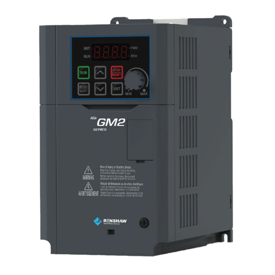
RSi GM2 Series
Variable Frequency Drive
1.0 to 15HP - 230V
1.0 to 15HP - 460V
Instruction Manual
Advertisement
Table of Contents
Troubleshooting

Related Manuals for BENSHAW RSi GM2 Series


Summary of Contents for BENSHAW RSi GM2 Series
- Page 1 1.0 to 15HP - 460V Instruction Manual 890054-00-00 © 2020 Benshaw Inc. Benshaw retains the right to change specifications and illustrations in text without prior notification. The contents of this document may not be copied without the explicit permission of Benshaw.
- Page 3 Safety Information tion Safety Information Read and follow all safety instructions in this manual precisely to avoid unsafe operating conditions, property damage, personal injury, or even death. Safety Symbols in This Manual Indicates an imminently hazardous situation which, if not avoided, will result in severe injury or even death.
- Page 4 Safety Information • Do not allow foreign objects, such as screws, metal chips, debris, water, or oil to get inside the inverter. Allowing foreign objects inside the inverter may cause the inverter to malfunction or result in a fire. • Do not operate the switch with wet hands. Otherwise it may cause an electrical shock and result in personal injury or even death.
-
Page 5: Table Of Contents
Table of Contents Table of Contents Preparing the Installation ..................1 Product Identification ....................... 1 Part Names ........................... 2 Installation Considerations ..................... 4 Selecting the Installation Site ....................5 Cable Selection ..........................7 Installing the Inverter ....................8 Mounting the Inverter ......................10 Wiring ……………………………………………………………………………………………………………...13 Post-Installation Checklist ..................... - Page 6 Table of Contents Frequency Reference Configuration .................. 51 Set the Frequency Reference from the Keypad - Direct Input ... 51 Set the Frequency Reference from the Keypad - Using [▲] and [▼] keys 51 Set the Frequency Reference using the V1 Terminal ......52 Set the Frequency Reference using V0, Built-in Potentiometer ..
- Page 7 Table of Contents Deceleration Stop ....................82 DC Braking After Stop ..................83 Free Run Stop ......................84 Power Braking ....................... 84 Frequency Limit ........................85 Frequency Limit Using Maximum Frequency and Start Frequency .. 85 Frequency Limit Using Upper and Lower Limit Frequency Values ..85 Frequency Jump ....................
- Page 8 Table of Contents Operational Noise Settings (Carrier Frequency Settings) ........133 2nd Motor Operation ......................134 Commercial Power Source Transition ................. 135 Cooling Fan Control ......................136 Input Power Frequency and Voltage Settings ............136 Parameter Save ........................137 Parameter Initialization ..................... 137 Parameter Lock ........................
- Page 9 Table of Contents Operation Mode on Option Card Trip ............173 No Motor Trip ....................174 Low Voltage Trip 2 ................... 174 Inverter pre-overheat warning ..............175 Torque Detection Protection Action ............176 RS-485 Communication Features ................ 179 Communication Standards ....................179 Communication System Configuration .................
- Page 10 Table of Contents Protection Function Group (PAR→Pr) ................. 233 2nd Motor Function Group (PAR→M2) ..............237 Troubleshooting ....................239 Trip and Warning ........................239 Faults ........................239 Warning Messages ................... 242 Troubleshooting Faults ....................... 243 Other Faults ..........................245 Maintenance......................248 Periodic Inspection Summary ..................
-
Page 11: Preparing The Installation
Preparing the Installation 890054-00-00 Preparing the Installation This chapter provides details on product identification, part names, correct installation and cable specifications. To install the inverter correctly and safely, carefully read and follow the instructions. Product Identification The GM2 Inverter is manufactured within a range of 1 HP ~ 15 HP (Normal Duty) and 0.5 HP ~ 10 HP (Heavy Duty) for both 240V or 480V input voltage ratings. -
Page 12: Part Names
Preparing the Installation 890054-00-00 Part Names See the assembly diagram below to identify names and locations of parts on the inverter. Detailed images may vary between product groups. ND: 1.0 HP ~ 7.5 HP, 240V/480V HD: 0.5 HP ~ 5.0 HP HD: 0.4 kW ~ 4.0 kW GM2 Series VFD... - Page 13 Preparing the Installation 890054-00-00 ND: 10 HP ~ 15 HP, 240V/480V HD: 7.5 HP ~ 10 HP HD: 5.5 kW ~ 7.5 kW GM2 Series VFD...
-
Page 14: Installation Considerations
Preparing the Installation 890054-00-00 Installation Considerations Inverters are composed of various precision electronic devices and the installation environment can significantly impact the lifespan and reliability of the product. The table below details the ideal installation and operating conditions for the inverter. Items Description Ambient... -
Page 15: Selecting The Installation Site
Preparing the Installation 890054-00-00 Selecting the Installation Site When selecting an installation location consider the following points: • The location must be free from vibration, and the inverter must be installed on a wall that can support the inverter’s weight. •... - Page 16 Preparing the Installation 890054-00-00 • If you are installing multiple inverters in one location, side-by-side mounting is acceptable with minimal spacing (~2.5mm) between inverters. Do not install the cover (option) shown in diagram. • If you are installing multiple inverters of different ratings, provide sufficient clearance above and below and to side walls to meet the clearance specifications of the larger inverter.
-
Page 17: Cable Selection
Preparing the Installation 890054-00-00 Cable Selection When you install power and signal cables in the terminal blocks, only use cables that meet the required specification for the safe and reliable operation of the product. Refer to the following information to assist you with cable selection. •... -
Page 18: Installing The Inverter
Installing the Inverter 890054-00-00 Installing the Inverter This chapter describes the physical and electrical installation methods, including mounting and wiring of the inverter. Refer to the flowchart and basic configuration diagram provided to understand the procedures and installation methods to be followed to install the product correctly. DIN Rail Mounting The inverters include provisions for standard DIN rail (35mm x 7.5mm) mounting. - Page 19 Installing the Inverter 890054-00-00 Basic Configuration The diagram below shows the basic system configuration. Use the diagram for reference when configuring the system by connecting the product with peripheral devices. Ensure that the product has a suitable rating for the configuration and that all the required peripherals and optional devices (brake unit, reactors, noise filters, etc.) are available.
-
Page 20: Mounting The Inverter
Installing the Inverter 890054-00-00 Mounting the Inverter Mount the inverter on a wall or inside a panel following the procedures provided below. Before installation, ensure that there is sufficient space to meet the clearance specifications, and that there are no obstacles impeding the cooling fan’s air flow. Select a wall or panel suitable to support the installation. - Page 21 Installing the Inverter 890054-00-00 Note The dimensions of the mounting holes vary based on the frame size. Refer to 11.3 External Dimensions on page 257 for detailed information about your model. GM2 Series VFD...
- Page 22 Installing the Inverter 890054-00-00 • Do not handle the inverter by lifting with the inverter’s covers or plastic surfaces. The covers are removeable and may come off if handled by the covers, causing injuries or damage to the product. Always handle the inverter by the metal frames. •...
-
Page 23: Wiring
Installing the Inverter 890054-00-00 Wiring Follow the seven steps for Cover removal, Ground Wire, Power Wire, Control Wire connections and EMC Filter connection. Complete the cable connections by connecting appropriately rated cables for ground, power and control terminal blocks. Read the following information carefully before carrying out wiring connections to the inverter. - Page 24 Installing the Inverter 890054-00-00 Step1 Remove the front cover The front cover must be removed to access the power and control terminals. Note that the disassembling procedure of front cover and control terminal cover may vary depending on the product group. Disassemble each cover in the following order: Loosen the screw that secures the front cover.
- Page 25 Installing the Inverter 890054-00-00 Step2 Ground Connection Locate the ground terminal and connect an appropriately rated ground cable to the terminals. Refer to 1.5 Cable Selection on page 7 to find the appropriate cable specification for your installation. Connect the other ends of the ground cables to the supply earth (ground) terminal. Note •...
- Page 26 Installing the Inverter 890054-00-00 Step3 Power Terminal Wiring The following illustrations show the terminal layout of the power terminals for each of the inverter ratings. Refer to the label and descriptions to understand the function and location of each terminal before making wiring connections. Ensure that the cables selected meet or exceed the specifications in 1.5 Cable Selection on page 7 before installing them.
- Page 27 Installing the Inverter 890054-00-00 HD 2.0 HP -> 3.0 HP (1.5 kW -> 2.2 kW) ND 3.0 HP -> 5.0 HP (2.2 kW -> 4.0 kW) HD 5.0 HP (4.0 kW) ND 7.5 HP (5.5 kW) HD 7.5 HP -> 10 HP (5.5 kW -> 7.5 kW) ND 10.0 HP ->...
- Page 28 Installing the Inverter 890054-00-00 Power Terminal Labels and Descriptions Terminal Labels Name Description Ground Terminal Connect earth grounding. AC power input R(L1)/S(L2)/T(L3) Mains supply AC power connections. terminal Brake resistor B1/B2 Brake resistor wiring connection. terminals Motor output 3-phase induction motor wiring U/V/W terminals connections.
- Page 29 Installing the Inverter 890054-00-00 • Power supply cables must be connected to the R, S, and T terminals and output wiring to the motor must be connected to the U, V, and W terminals. Opposite connections may damage the product. •...
- Page 30 Installing the Inverter 890054-00-00 Input Terminal Labels and Descriptions Terminal Category Name Description Labels Configurable multi-function (digital) input terminals. Factory defaults are setup as follows: • P1: Fx Multi-function Multi- P1–P5 • P2: Rx (digital) Input 1-5 function (digital) • P3: BX terminal •...
- Page 31 Installing the Inverter 890054-00-00 Terminal Category Name Description Labels Current input for 0(4) - 20mA reference Current input for frequency. frequency • Input current: 4–20 mA reference input • Maximum Input current: 20 mA Terminal • Input resistance: 249 Ω Output/Communication Terminal Labels and Descriptions Terminal Category...
- Page 32 Installing the Inverter 890054-00-00 Pre-insulated Crimp Terminal Use pre-insulated crimp terminal connectors to increase reliability of the control terminal wiring. Refer to the specifications below to determine the crimp terminals to fit various cable sizes. Cable Dimensions (inches/mm) Spec. AWG mm 0.50 0.4/12.0 0.2/6.0 0.05/1.3 0.13/3.2 0.75 0.4/12.0 0.2/6.0 0.06/1.5 0.13/3.4 1.0 0.4/12.0 0.2/6.0 0.07/1.7 0.14/3.6...
- Page 33 Installing the Inverter 890054-00-00 Step 5 PNP/NPN Mode Selection The GM2 inverter supports both PNP (Source) and NPN (Sink) modes for activating the digital inputs at the control board terminals. Select an appropriate mode to suit switching requirements using the PNP/NPN selection switch (SW1) on the control board. The following describes each mode along with connection diagrams.
- Page 34 Installing the Inverter 890054-00-00 Step 6 Disabling the EMC Filter for Power Sources with Asymmetrical Grounding Applies to 480V models only. When connecting the inverter to a power source with asymmetrical grounding (see figures below), the internal EMC filter must be disabled. The Built-in EMC filter is enabled by factory default.
- Page 35 Installing the Inverter 890054-00-00 Before using the inverter, confirm the grounding system of the power source. Disable the EMC filter if the power source has an asymmetrical grounding connection. Check the location of the EMC filter screw. To disable, remove the screw and install the plastic washer. Washer is located under the control terminal block.
-
Page 36: Post-Installation Checklist
Installing the Inverter 890054-00-00 Post-Installation Checklist After completing the installation, check the items in the following table to make sure that the inverter has been safely and correctly installed. Items Details Ref. Result Is the installation location appropriate? Does the environment meet the inverter’s operating conditions? Does the power source match the inverter’s rated Installation... - Page 37 Installing the Inverter 890054-00-00 Items Details Ref. Result If 3-wire operation is required, are the multi- function (digital) input terminals programmed p.19 prior to the connection of the control wiring? Are the control cables properly wired? p.19 Are the control terminal screws tightened to their p.19 specified torques? Is the total cable length of all control wiring less...
-
Page 38: Test Run
Installing the Inverter 890054-00-00 Test Run After the post-installation checklist has been completed, follow the instructions below to test the inverter. Turn on the power supply to the inverter. Ensure that the keypad display light is on. Verify Motor Rotation On the keypad, set the drv parameter (command source) in the Operation group to 0 (Keypad). -
Page 39: Perform Basic Operations
Perform Basic Operations 890054-00-00 Perform Basic Operations This chapter describes: The keypad layout - display and buttons (or keys) • Button (or key) operation • Parameter groups and navigation • Viewing and changing parameter settings • Specific examples for setting the most common functions •... -
Page 40: Operation Keys
Perform Basic Operations 890054-00-00 The table below shows how characters (letters and numbers) are displayed. Number Number Number Number Display Display Display Display characte characte characte characte Operation Keys The following table lists the names and functions of the keypad’s operation keys. Name Function [RUN] key... - Page 41 Perform Basic Operations 890054-00-00 Name Function * Operates as ESC key when two keys are entered at the same time. - While in the group navigation mode, use ESC to go ESC* to the initial screen (the frequency display screen). - While in the parameter change mode (SET LED lit), use ESC to go to group navigation mode without saving.
-
Page 42: Control Menu
Perform Basic Operations 890054-00-00 Control Menu The following table lists the parameter groups and a description of functions within each group. Keypad Group Description Display Configures Acc/Dec times, Start/Stop and Operation Reference Frequency sources. Configures drive Control Mode, Jog operation, Drive Motor HP setting, torque boost, and parameter Read/Write/Save/Initialize. -
Page 43: Learning To Use The Keypad
Perform Basic Operations 890054-00-00 Learning to Use the Keypad The keypad enables movement between groups and parameter codes. It also enables users to select and configure functions. At parameter level, you can set parameter values and turn on or off specific functions, or decide how the functions will be used. -
Page 44: Navigating Directly To Different Codes (Jump Codes)
Perform Basic Operations 890054-00-00 Navigating Directly to Different Codes (Jump Codes) The following examples detail navigating to code dr. 95, from the initial code in the Drive group (dr. 0). Using the arrow keys, pressing [UP] will loop backwards from dr.0 to dr.95. The table shows how to program in the parameter number and jump directly to it. -
Page 45: Setting Parameter Values
Perform Basic Operations 890054-00-00 Setting Parameter Values The example below shows how to directly enter parameter values, such as frequency references, supply voltages, and motor speeds. You can also enable or disable other features. Follow the instructions below to set or modify parameter values. Step Instruction Keypad Display... -
Page 46: Actual Application Examples
Perform Basic Operations 890054-00-00 Actual Application Examples Acceleration Time Configuration The following demonstrates how to modify the Acceleration time (ACC) parameter value (from 5.0 to 16.0) in the Operation group. Step Instruction Keypad Display Ensure that the first code of the Operation group is selected, and 0.00 code 0.00 (Reference frequency) is displayed. -
Page 47: Frequency Reference Configuration
Perform Basic Operations 890054-00-00 Frequency Reference Configuration The following demonstrates configuring a reference frequency of 30.05 Hz from the first code in the Operation group. Step Instruction Keypad Display Ensure that the first code of the Operation group is selected, and code 0.00 (Reference frequency) is 0.00 displayed. -
Page 48: Jog Frequency Configuration
Perform Basic Operations 890054-00-00 Jog Frequency Configuration The following demonstrates how to configure Jog Frequency by modifying code dr.11 (Jog Frequency) in the Drive group from 10.00 Hz to 20.00 Hz. You can configure other parameters in different groups exactly the same way. Step Instruction Keypad Display... -
Page 49: Parameter Initialization
Perform Basic Operations 890054-00-00 Parameter Initialization The following demonstrates parameter initialization using code dr.93 (Parameter Initialization) in the Drive group. Jumping to parameter dr.93 is used. Step Instruction Keypad Display Go to code 0 in the Drive group. dr.0 Press the [ENT] key. The current parameter value "9"... -
Page 50: Frequency Setting (Keypad) And Operation (Via Terminal Input)
Perform Basic Operations 890054-00-00 Frequency Setting (Keypad) and Operation (via Terminal Input) Step Instruction Keypad Display Turn on the inverter. Ensure that the first code of the Operation group is selected, and code 0.00 (Reference frequency) is 0.00 displayed, then press the [ENT] key. The first number on the right side of the display will flash. -
Page 51: Frequency Setting (Potentiometer) And Operation (Terminal Input)41
Perform Basic Operations 890054-00-00 Frequency Setting (Potentiometer) and Operation (Terminal Input) Step Instruction Keypad Display Turn on the inverter. Ensure that the first code of the Operation group is selected, and code 0.00 (Reference frequency) is 0.00 displayed. Press the [▲] key 4 times. Move to the Frq (Frequency reference source) parameter. - Page 52 Perform Basic Operations 890054-00-00 [Wiring Diagram] [Operation Pattern] Note The instructions in the table are based on the factory default parameter settings. The inverter may not work correctly if the default parameter settings were changed. In such cases, initialize all parameters to reset the values to factory default parameter settings before following the instructions in the table (refer to 5.21 Parameter Initialization on page 137).
-
Page 53: Frequency Setting With (Internal) Potentiometer And Start Command With The Keypad [Run] Key
Perform Basic Operations 890054-00-00 Frequency setting with (internal) potentiometer and start command with the keypad [RUN] key Step Instruction Keypad Display Turn on the inverter. Ensure that the first code of the Operation group is selected, and code 0.00 (Reference frequency) is 0.00 displayed. - Page 54 Perform Basic Operations 890054-00-00 [Wiring Diagram] [Operation Pattern] Note The instructions in the table are based on the factory default parameter settings. The inverter may not work correctly if the default parameter settings are changed. In such cases, initialize all parameters to reset the values to factory default parameter settings before following the instructions in the table (refer to 5.21 Parameter Initialization on page 137).
-
Page 55: Monitoring The Operation
Perform Basic Operations 890054-00-00 Monitoring the Operation Output Current Monitoring The following demonstrates how to monitor the output current in the Operation group using the keypad. Step Instruction Keypad Display Ensure that the first code of the Operation group is selected, and code 0.00 (Reference frequency) is 0.00 displayed. -
Page 56: Trip Condition Monitor
Perform Basic Operations 890054-00-00 Trip Condition Monitor The following demonstrates how to monitor fault conditions in the Operation group using the keypad. Step Instruction Keypad Display Refer to the example keypad display. An over current trip fault has occurred. Press the [ENT] key, and then the [▲] key. The operating frequency at the time of the fault (30.00 30.00 Hz) is displayed. - Page 57 Perform Basic Operations 890054-00-00 Note • If multiple faults occur at the same time, a maximum of 3 fault records can be retrieved as shown in the following example. • If a warning situation occurs while operating with the entered frequency, a warn display and the current screen will flash in 1 second intervals.
- Page 58 Perform Basic Operations 890054-00-00 GM2 Series VFD...
-
Page 59: Learning Basic Features
Learning Basic Features 890054-00-00 Learning Basic Features This chapter describes basic features of the GM2 inverter. Check the reference page in the table to see the detailed description for each of the basic features. Basic Tasks Use Example Ref. Set the keypad as the Configures the inverter to setup and modify the p.51 frequency reference source. - Page 60 Learning Basic Features 890054-00-00 Basic Tasks Use Example Ref. Disables the current acceleration or deceleration rate and Acc/Dec stop command holds the inverter output frequency (motor speed) at p.74 configuration the most recent speed. Increase and decrease the inverter output at a fixed V/F Linear V/F pattern operation ratio.
-
Page 61: Frequency Reference Configuration
Learning Basic Features 890054-00-00 Frequency Reference Configuration The GM2 inverter provides several methods to setup and modify the frequency reference. Choices include the keypad, analog inputs of voltage (V0 or V1) and current (I2), RS-485 (Modbus), or Fieldbus option cards. Group Code Name... -
Page 62: Set The Frequency Reference Using The V1 Terminal
Learning Basic Features 890054-00-00 Set the Frequency Reference using the V1 Terminal You can modify the frequency reference using the V1 input terminal at the control board. Use voltage inputs ranging from 0 to 10 V (unipolar) or from -10 to +10 V (bipolar) for both directions, where negative voltage inputs are used for reverse operations. - Page 63 Learning Basic Features 890054-00-00 0–10 V Input Voltage Setting Details Code and Description Features Configures the output frequency at the maximum analog input voltage. In.01 The frequency set with In.01 becomes the maximum frequency when Freq at 100% the value set in code In.11 (for unipolar) or In.15 (for bipolar) is 100%. In.05 Display the value of the input voltage at V1.
- Page 64 Learning Basic Features 890054-00-00 Code and Description Features Quantizing may be used when the noise level is high in the analog input signal. The inverter output frequency changes in consistant intervals (steps) based on measuring (quantizing) the height (value) of the analog input signal.
- Page 65 Learning Basic Features 890054-00-00 4.1.3.2 Setting a Frequency Reference for -10–+10 V Input Set parameter Frq in the Operations group to 2 (V1) and set parameter In.06 (V1 Polarity) to 1 (bipolar). Connect an external -10- +10V source (PLC or other) to the V1-CM terminals. [Connecting to -10 –+10 V external source] [Bipolar input voltage and output frequency] -10V - +10V Input Voltage Settings...
- Page 66 Learning Basic Features 890054-00-00 Rotational Directions for Different Voltage Inputs Input voltage Run command 0–10 V -10–0 V -10–+10 V Voltage Input Setting Details Code and Description Features These parameters are used to configure the offset and gradient level (slope) values of the analog input to the required inverter output. These parameters are displayed only when In.06 is set to 1 (bipolar).
-
Page 67: Set The Frequency Reference Using V0, Built-In Potentiometer
Learning Basic Features 890054-00-00 Set the Frequency Reference using V0, Built-in Potentiometer You can modify the frequency reference using the built-in potentiometer. Set Frq (Frequency reference source) to 4 (V0). View the frequency reference at the 0.00 (Main screen) Scaling of the V0 input is done with In.38 through In.41. in the Operations group. - Page 68 Learning Basic Features 890054-00-00 Input Current (I2) Setting Details Code and Description Features Configures the output frequency at the maximum analog input current. In.01 Freq at The frequency set with In.01 becomes the maximum frequency when 100% the value set in In.56 is set to 100%. In.50 I2 Monitor Display the value of the input current at I2.
-
Page 69: Setting The Frequency Reference Using Rs-485 Communication
Learning Basic Features 890054-00-00 Setting the Frequency Reference using RS-485 Communication Set parameter Frq (Frequency reference source) 6 (Int 485). Control the inverter with upper-level controllers (PCs or PLCs) via RS-485 communications using the (S+/S-) input terminals of the control board. Refer to 7 RS-485 Communication Features on page 179 for more details. RS-485 Communication Settings Group Code... -
Page 70: Multi-Step Frequency Configuration
Learning Basic Features 890054-00-00 Multi-step Frequency Configuration Multi-step operations (Fixed Speed Inputs) can be assigned to the Px terminals. Step 0 uses the frequency reference source set with Frq in the Operations group. Steps 1 through 7 can be configured using (3) digital input terminals. Set Px terminals to 7 (Speed-L), 8 (Speed-M) and 9 (Speed-H). - Page 71 Learning Basic Features 890054-00-00 Code and Description Features Choose (3) of the digital input terminals (P1 ~ P5) to setup as multi- step inputs. Set (3) of the correspondinig parameters (In.65~In.69) to 7 (Speed-L), 8 (Speed-M), or 9 (Speed-H). Example using terminals P3, P4 and P5 set to Speed-L, Speed-M and Speed-H respectively, the following multi-step operation will be available.
-
Page 72: Command Source (Start/Stop) Configuration
Learning Basic Features 890054-00-00 Command Source (Start/Stop) Configuration The GM2 inverter provides several methods to Start and Stop the inverter. Choices include the keypad, digital input terminals, RS-485 (Modbus), or Fieldbus option cards. Group Code Name Setting Setting Range Unit Keypad Fx/Rx-1 Command... -
Page 73: Setting The Terminal Block As A Command Input Device - Run And Rotation Direction Commands
Learning Basic Features 890054-00-00 Setting the Terminal Block as a Command Input Device - Run and Rotation Direction Commands Set parameter drv (command source) to 2 (Fx/Rx-2). This configuration (Fx/Rx-2) assigns the Fx terminal as the Start/Stop input terminal and assigns the Rx terminal as the rotational direction input terminal (Open: Fwd, Closed: Rev). -
Page 74: Setting Rs-485 Communications As A Command Input Device
Learning Basic Features 890054-00-00 Setting RS-485 Communications as a Command Input Device Set drv (command source) to 3 (Int 485). Control the inverter with upper-level controllers (PCs or PLCs) via RS-485 communications using the (S+/S-) input terminals of the control board. Refer to 7 RS-485 Communication Features on page 179 for more details. -
Page 75: Power-On Run
Learning Basic Features 890054-00-00 Power-on Run The inverter can be set to start operating (output power to the motor) as soon as the inverter powers up. See caution below. When Ad.10, Power-on Run is set to 1 (yes) and a run command remains enabled, the inverter will start immediately upon power up. -
Page 76: Reset And Restart
Learning Basic Features 890054-00-00 Reset and Restart The inverter can be set to automatically reset faults and restart operations. See caution below. When Pr.08 is set to 1 (yes) and a run command remains enabled, the inverter will reset the fault and restart. -
Page 77: Setting Acceleration And Deceleration Times
Learning Basic Features 890054-00-00 Setting Acceleration and Deceleration Times Acc/Dec Time Based on Maximum Frequency Acc/Dec times are based on maximum frequency (bA.08 set to 0 (MaxFreq)), not on inverter operating frequency. Acceleration time set at ACC refers to the time required for the inverter to reach the maximum frequency from a stopped (0 Hz) state. -
Page 78: Acc/Dec Time Based On Operating Frequency
Learning Basic Features 890054-00-00 Note that the time values may change automatically when the units are changed. If the acceleration time is set at 6000 seconds, changing bA.09 from a time scale of 1 second to 0.01 second will result in a modified acceleration time of 60.00 seconds. Acc/Dec Time Based on Operating frequency Acc/Dec times can be set based on the time required to reach the next step frequency from the existing operating frequency. -
Page 79: Multi-Step Acc/Dec Time Configuration
Learning Basic Features 890054-00-00 Multi-step Acc/Dec Time Configuration Digital input terminals can be configured for different Acc and Dec times. Up to 7 acceleration times and 7 deceleration times can be set. Choose (up to 3) digital input terminals (P1 ~ P5) and set the corresponding parameters (In.65~In.69) to 11 (XCEL-L), 12 (XCEL-M) and 49 (XCEL-H). - Page 80 Learning Basic Features 890054-00-00 Code and Description Features Choose and configure the terminals to use for multi-step Acc/Dec time inputs. Configuration Function XCEL-L Acc/Dec command-L XCEL-M Acc/Dec command-M XCEL-H Acc/Dec command-H Acc/Dec commands are recognized as binary code inputs and will control the acceleration and deceleration based on parameter values set with bA.70 ~ bA–82 and bA.71 ~ bA–83.
-
Page 81: Acc/Dec Time Switch Frequency
Learning Basic Features 890054-00-00 Acc/Dec Time Switch Frequency You can set a switch frequency (Ad.60) to switch between 2 different Accel times and 2 different Decel times. Parameters bA.70 (step accel time1) and bA.71 (step decel time1) are in effect below the switch frequency. -
Page 82: Acc/Dec Pattern Configuration
Learning Basic Features 890054-00-00 Acc/Dec Pattern Configuration A Linear Accel and Decel pattern features a linear increase (and decrease) of the output frequency at a fixed rate. An S-curve pattern provides a smoother and more gradual increase (and/or decrease) of output frequency. Acc/Dec gradient level patterns can be configured to enhance and smooth the inverter’s acceleration and deceleration curves. - Page 83 Learning Basic Features 890054-00-00 [Linear vs. S-Curve Acceleration / deceleration pattern configuration] [Acceleration / deceleration S-curve pattern configuration] The actual Acc/Dec times become greater than user defined Acc/Dec times when S-curve Acc/Dec patterns are applied. Example: The Actual Acc/Dec time during an S-curve application Actual acceleration time = ACC + (ACC x Ad.03/2) + (ACC x Ad.04/2) Settings: ACC = 10 secs., Ad.03 = 50%, Ad.04 = 50% Actual acceleration time = 10 + (10 x .5/2) + (10 x .5/2) = 15 secs.
-
Page 84: Stopping The Acc/Dec Operation
Learning Basic Features 890054-00-00 Stopping the Acc/Dec Operation Configures a digital input terminal to stop acceleration or deceleration and operate the inverter at a fixed frequency. Group Code Name Setting Setting Range Unit 65~69 Px terminal XCEL Stop 0–52 V/F Control Configure the inverter’s output voltages, gradient levels and output patterns to achieve a target output frequency with V/F control. - Page 85 Learning Basic Features 890054-00-00 Linear V/F Pattern Setting Details Code and Description Features Sets the base frequency. A base frequency is the inverter’s output dr.18 frequency when applying the motor’s rated voltage. Refer to the Base Freq motor’s nameplate to set this parameter. Sets the start frequency.
-
Page 86: Square Reduction V/F Pattern Operation
Learning Basic Features 890054-00-00 Square Reduction V/F Pattern Operation Square reduction V/F pattern is ideal for variable torque loads such as fans and pumps that do not require high torque at frequencies lower than base frequency. The inverter provides a non-linear V/F acceleration and deceleration pattern to sustain enough torque throughout the speed range. -
Page 87: User V/F Pattern Operation
Learning Basic Features 890054-00-00 User V/F Pattern Operation The inverter allows the configuration of user-defined V/F patterns to suit the characteristics of special motors/loads. Group Code Name Setting Setting Range Unit V/F pattern 2 User V/F 0–3 User Frequency 1 15.00 0–Max Frequency User Voltage 1 0–100... -
Page 88: Torque Boost
Learning Basic Features 890054-00-00 Torque Boost Manual Torque Boost Manual torque boost enables users to adjust output voltage during motor starting and low speed operation. This setting improves motor starting properties and increases low speed torque. Configure manual torque boost for loads that require high starting torque. Group Code Name Setting... -
Page 89: Auto Torque Boost
Learning Basic Features 890054-00-00 Auto Torque Boost In V/F operation, auto torque boost adjusts the output voltage when the motor cannot be started due to lack of starting torque. It provides a calculated voltage boost based on torque current. Group Code Name Setting... -
Page 90: Motor Output Voltage Adjustment
Learning Basic Features 890054-00-00 Motor Output Voltage Adjustment Output voltage settings are required when a motor’s rated voltage differs from the input voltage to the inverter. Set the voltage to the motor’s rated operating voltage. The set voltage becomes the output voltage at the inverter’s base frequency. - Page 91 Learning Basic Features 890054-00-00 Group Code Name Setting Setting Range Unit 0-Rated Current of Amount of applied Inverter/Rated Current of Motor x 100% The amount of DC braking required is based on the motor’s rated current. If the DC braking current is too high or brake time is too long, the motor may overheat or be damaged.
-
Page 92: Initial Excitation (Pre-Excite)
Learning Basic Features 890054-00-00 Initial Excitation (Pre-excite) The inverter can supply excitation current to the motor when controlled by a digital input during a stopped condition. When a digital input is set to 34 (Pre-excite) and activated, the inverter will output DC voltage to the motor. -
Page 93: Dc Braking After Stop
Learning Basic Features 890054-00-00 DC Braking After Stop DC Braking can be applied to the motor during deceleration. The inverter stops the motor by supplying DC power to the motor. Settings include a delay time, a brake time, a brake current level and a brake frequency. -
Page 94: Free Run Stop
Learning Basic Features 890054-00-00 Free Run Stop When the run command is removed, the inverter output turns off and the motor/load coasts to a stop. Group Code Name Setting Setting Range Unit Stop Mode Free-Run 0–4 Note: With high inertia loads, the load’s inertia will cause the motor to continue rotating. The inverter does not control the motor during Free-Run. -
Page 95: Frequency Limit
Learning Basic Features 890054-00-00 Frequency Limit The inverter output frequency can be limited by setting frequency limit parameters. These include start frequency, maximum frequency, upper and lower frequency limits. Frequency Limit Using Maximum Frequency and Start Frequency Group Code Name Setting Setting Range Unit... -
Page 96: Frequency Jump
Learning Basic Features 890054-00-00 Frequency Jump Use frequency jump to avoid mechanical resonance frequencies. Jump through up to three frequency bands during acceleration and deceleration. Reference frequencies cannot be set within the pre-set jump frequency band. When the reference frequency is increased it will be maintained at the lower limit of a jump frequency band. -
Page 97: Nd Operation Mode
Learning Basic Features 890054-00-00 Operation Mode Operation Mode is commonly refered to as Hand-Off-Auto switching or Local-Off-Remote switching. The inverter can be operated (Start/Stop and Reference frequency) with two types of operating modes and switch between them as required. The first Start/Stop source and Reference Frequency source are set with parameters drv and Frq in the Operations group. -
Page 98: Multi-Function (Digital) Input Terminal Control
Learning Basic Features 890054-00-00 Multi-function (digital) Input Terminal Control Filter time constants (On Delay and Off Delay) can be applied independently to the digital inputs. Longer time settings will delay the response of the input. Additionally, the digital inputs can be configured independently as a normally open input or a normally closed input. - Page 99 Learning Basic Features 890054-00-00 Multi-function (digital) Input Terminal Control Setting Details Code and Description Features Select whether or not to activate the time values set at In.85 and In.86 to selected terminals. If the terminal is not enabled, the time values are set to the default values.
-
Page 100: Fire Mode Operation
Learning Basic Features 890054-00-00 Fire Mode Operation Fire Mode operation is for use in emergency situations. When enabled, Fire Mode allows the inverter to provide continuous operation ignoring the majority of faults. Primarily used for fire pump operation, but can be applied when continuous operation is required due to emergencies. When enabled, Fire mode forces the inverter to ignore all minor faults and repeats a Reset/Restart of major faults, regardless of the Reset/Restart count limit. - Page 101 Learning Basic Features 890054-00-00 Code Description Details The majority of faults are ignored during Fire mode operation. The fault history is saved. Output relays set to trip functions are disabled. Faults that are ignored in Fire mode BX, External Trip, Low Voltage Trip, Inverter Overheat, Inverter Overload, Overload, Electrical Thermal Trip, Input/Output Open Phase, Motor Overload, Fan Trip, No Motor Trips, and other minor faults.
-
Page 102: Learning Advanced Features
Learning Advanced Features 890054-00-00 Learning Advanced Features This chapter describes the advanced features of the GM2 inverter. Check the reference page in the table to see the detailed description for each of the application features. Advanced Tasks Use Example Ref. Use the main and auxiliary frequencies with the predefined Auxiliary frequency formulas to create various operating conditions. - Page 103 Learning Advanced Features 890054-00-00 Advanced Tasks Use Example Ref. Used to switch equipment operation by connecting two Motor motors to one inverter. Configure and operate the second p.134 Operation motor when the input terminal is activated. Used to switch the power source to the motor from the Commercial power inverter output to a commercial power source, and vice p.135...
-
Page 104: Operating With Auxiliary References
Learning Advanced Features 890054-00-00 Operating with Auxiliary References Frequency references can be configured with various calculated conditions that use the main and auxiliary frequency references simultaneously. The main frequency reference (Frq) is used as the operating frequency, while the auxiliary reference is used to modify and fine-tune the main reference. - Page 105 Learning Advanced Features 890054-00-00 Code and Description Features The table below list the available calculated conditions for the main and auxiliary frequency references. Set the auxiliary reference gain with bA.03 (Aux Ref Gain) to configure the auxiliary reference and set the percentage to be reflected when calculating the main reference.
- Page 106 Learning Advanced Features 890054-00-00 The tables below provide examples of using the available calculated conditions for the main and auxiliary frequency references. Refer to the table to see how the calculations apply with each example. When the maximum frequency value is high, output frequency deviation may result due to analog input variation and deviations in the calculations.
- Page 107 Learning Advanced Features 890054-00-00 Setting* Calculating final reference frequency M[Hz]+(G[%]*A[Hz]) 30 Hz(M)+(50%(G)x24 Hz(A))=42 Hz M[Hz]*(G[%]*A[%]) 30 Hz(M)x(50%(G)x40%(A))=6 Hz M[Hz]/(G[%]*A[%]) 30 Hz(M)/(50%(G)x40%(A))=150 Hz M[Hz]+{M[Hz]*(G[%]*A[%])} 30 Hz(M)+{30[Hz]x(50%(G)x40%(A))}=36 Hz M[Hz]+G[%]*2*(A[%]-50[%])[Hz] 30 Hz(M)+50%(G)x2x(40%(A)–50%)x60 Hz=24 Hz M[HZ]*{G[%]*2*(A[%]-50[%]) 30 Hz(M)x{50%(G)x2x(40%(A)–50%)} = -3 Hz(Reverse) M[HZ]/{G[%]*2*(A[%]-50[%])} 30 Hz(M)/{50%(G)x2x(60%–40%)} = -300 Hz(Reverse) M[HZ]+M[HZ]*G[%]*2*(A[%]-50[%]) 30 Hz(M)+30 Hz(M)x50%(G)x2x (40%(A)–50%)=27 Hz * M: Main frequency reference/ G: Auxiliary reference gain (%)/ A: Auxiliary frequency...
-
Page 108: Jog Operation
Learning Advanced Features 890054-00-00 Jog Operation The jog operation allows for a temporary control of the inverter. There are two was to apply a jog and start command using the multi-function (digital) input terminals. Jog-1 using a digital input terminal set to JOG along with a start command (Fx or Rx). •... -
Page 109: Jog Operation 2-Fwd/Rev Jog By Multi-Function (Digital) Terminal
Learning Advanced Features 890054-00-00 Jog Operation 2-Fwd/Rev Jog by Multi-function (digital) Terminal A terminal that is set for a forward or reverse jog also starts the inverter. The table below lists parameter settings for a forward (or reverse) jog operation. A separate Run (Fx) command is not required. -
Page 110: Up-Down Operation
Learning Advanced Features 890054-00-00 Up-down Operation The inverter can control the speed of the motor using digital inputs set to the Up and Down functions. The Up/Down operation can be applied to systems that use upper-lower limit switches. Three digital inputs are required. One set to U/D Enable, and the other two for Up (increase speed) and Down (decrease speed) operation. - Page 111 Learning Advanced Features 890054-00-00 Up-down Operation Setting Details Code and Description Features Select three terminals for Up/Down operation and set them to 17 (Up), 18 (Down) and 27 (U/D Enable), respectively. When the U/D Enable input and the Up input are activated, the inverter will accelerate.
-
Page 112: 3-Wire Operation
Learning Advanced Features 890054-00-00 3-Wire Operation 3-wire operation is used to latch the run command input signal (FWD or REV) when using a momentary input. This configuration is commonly used to operate the inverter with a set of momentary push buttons. Group Code Name... -
Page 113: Safe Operation Mode
Learning Advanced Features 890054-00-00 Safe Operation mode This safety feature is used as a Run Enable/Disable input. When a digital input is set to 13 (Run Enable), the inverter will only operate when the input is closed (Enabled). The input must be closed to recognize other digital input functions. - Page 114 Learning Advanced Features 890054-00-00 Q-Stop Function When Ad.70 (Run En Mode) is set to 1 (DI Dependent) and Ad.71 is set to 2 (Q-Stop), if the Run Enable input is opened during operation, the inverter will decelerate to a stop based on the time set in Ad.72, Q-Stop Time.
-
Page 115: Dwell Operation
Learning Advanced Features 890054-00-00 Dwell Operation The dwell operation is used to maintain torque (speed) at programmed frequencies during the acceleration and deceleration process. This function is used in the application and release of the mechanical brakes on lift-type loads (elevators). Inverter dwell operation is based on the Acc/Dec dwell frequency (Ad.20, Ad.22) and the dwell time (Ad.21, Ad.23) set by the user. - Page 116 Learning Advanced Features 890054-00-00 Note Dwell operation does not work when: • Dwell operation time is set to 0 sec or dwell frequency is set to 0 Hz. • Re-acceleration is attempted from stop or during deceleration. Only the first acceleration dwell operation is valid through the complete process.
-
Page 117: Slip Compensation Operation
Learning Advanced Features 890054-00-00 Slip Compensation Operation Slip refers to the variation between the set frequency (speed) and actual motor rotation speed. During operation a set frequency, the slip will vary as the load changes. As the load increases, slip will increase. -
Page 118: Pid Control
Learning Advanced Features 890054-00-00 PID Control Pid control is one of the most common automatic control methods. It uses a combination of proportional, integral, and differential (PID) control that provides effective control for automated systems. The functions of PID control can be applied to the inverter operation for control of the following: Code Function Control speed by using feedback of the existing speed... - Page 119 Learning Advanced Features 890054-00-00 Group Code Name Setting Setting Range Unit PID controller 0–Max 0.00 motion frequency Frequency PID controller 0.0–100.0 motion level PID controller 0–9999 motion delay time PID sleep mode 60.0 0–999.9 delay time 0–Max PID sleep mode frequency 0.00 Frequency PID wake-up level...
- Page 120 Learning Advanced Features 890054-00-00 Code and Description Features Selects the reference source for PID control. The reference and feedback (AP.21) cannot be the same source. If V1 is set as the feedback source, V1 cannot be the reference source. To set V1 as a reference source (AP.20), change the feedback source (AP.21).
- Page 121 Learning Advanced Features 890054-00-00 Code and Description Features AP.43 PID Unit Gain, Adjusts the size to fit the unit. AP.44 PID Unit Scale The PID controller’s gain can be changed using the multi-function (digital) terminal. When a digital input terminal (In.65~69) is set to 24 AP.45 PID P2-Gain (P Gain2), and when activated, the gain set in AP.22 and AP.23 will be switched to the gain set in AP.45.
- Page 122 Learning Advanced Features 890054-00-00 [PID control block diagram] GM2 Series VFD...
-
Page 123: Pre-Pid Operation
Learning Advanced Features 890054-00-00 Pre-PID Operation Pre-PID is a function that allows the inverter to run at a set frequency (AP.34) for a set amount of time (AP.36) prior to normal PI Control operation. There is also a Pre-PID exit value (AP.35) that must be set. -
Page 124: Pid Switching (Pid Openloop)
Learning Advanced Features 890054-00-00 PID Operation Sleep Mode Setting Details Code and Features Description AP.37 PID Sleep DT, If an operating frequency lower than the value set in AP.38 is maintained for AP.38 PID Sleep the time set at AP.37, the operation stops and the inverter will enter sleep Freq mode. -
Page 125: Auto-Tuning
Learning Advanced Features 890054-00-00 Auto-tuning The motor parameters can be measured automatically and can be used for auto torque boost or sensorless vector control. Example - Auto-Tuning Based on 0.75kW, 200V, 60Hz, 4 Pole Motor Group Code Name Setting Setting Range Unit Motor capacity 0.75 kW... - Page 126 Learning Advanced Features 890054-00-00 Auto-Tuning Default Settings Motor No-load Rated Slip Stator Leakage Rated Capacity Current Frequency Resistance Inductance Current (A) (Rpm) () (mH) (kW) 14.0 40.4 6.42 38.8 0.75 2.951 25.20 1.156 12.07 200 V 0.809 6.44 13.8 0.485 4.02 20.0 0.283...
- Page 127 Learning Advanced Features 890054-00-00 Code Description As the motor is not rotating while the parameters are measured, the measurements are not affected when the load is connected to the motor spindle. However, when measuring parameters, do not rotate the motor spindle on the load side.
-
Page 128: Sensorless Vector Control For Induction Motors
Learning Advanced Features 890054-00-00 Sensorless Vector Control for Induction Motors Sensorless vector control provides a more accurate estimation of the motor rotation speed compared to V/F control. When auto tuning is completed, the inverter calculates motor speed and does not require the rotating speed feedback from the motor. Sensorless vector control can also generate greater torque at a lower level of current. -
Page 129: Sensorless Vector Control Operation Setting For Induction Motors119
Learning Advanced Features 890054-00-00 For high-performance operation, the parameters of the motor connected to the inverter output must be measured. Use auto tuning (bA.20 Auto Tuning) to measure the parameters before you run sensorless vector operation. To run high-performance sensorless vector control, the inverter and the motor must have the same capacity. If the motor capacity is smaller than the inverter capacity by more than two levels, control may be inaccurate. - Page 130 Learning Advanced Features 890054-00-00 Sensorless Vector Control Operation Setting Details for Induction Motors Code and Description Features Sets pre-excitation time. Pre-excitation is used at the start of the Cn.09 PreExTime operation to perform excitation up to the motor’s rated flux. Allows for the reduction of the pre-excitation time.
- Page 131 Learning Advanced Features 890054-00-00 Code and Description Features Select a source for torque limit setting. Either keypad, analog inputs (V1, V0 or I2) or communications. When setting torque limit, adjust the torque amount by limiting the speed controller output. Set the retrograde and regenerative limits for forward and reverse operation.
-
Page 132: Sensorless Vector Control Operation Guide For Induction Motors
Learning Advanced Features 890054-00-00 Sensorless Vector Control Operation Guide for Induction Motors Relevant Problem Troubleshooting Function Code If the number of motor If there is a severe drop in the motor rotation Cn.22 Out Trq. rotations drops due to to 36 RPM or more, increase the Cn.22 Out Trq. Comp. - Page 133 Learning Advanced Features 890054-00-00 Relevant Problem Troubleshooting Function Code If low speed (3 Hz or Cn.30 Spd. Sometimes control is not possible under a low less) out-of-phase Response speed due to high load inertia. In this case, occurs because the Adjustment Gain increase the Cn.30 value by 1 unit at a time.
-
Page 134: Kinetic Energy Buffering - Keb
Learning Advanced Features 890054-00-00 Kinetic Energy Buffering - KEB When the input power is disconnected, the inverter’s DC link voltage decreases, and a low voltage trip occurs blocking the output. Kinetic energy buffering operation can be used to decelerate the motor safely under these conditions. - Page 135 Learning Advanced Features 890054-00-00 Code and Description Features When the input power is disconnected, it charges the DC link with regenerated energy. When the input power is restored, the inverter changes to normal operation from the KEB-1 energy buffering KEB-1 operation.
- Page 136 Learning Advanced Features 890054-00-00 Code and Description Features The controller P Gain is for maintaining the voltage of the DC link section during the kinetic energy buffering operation. Change the Cn.80 KEB P Gain setting value when a low voltage trip occurs right after a power failure. The controller I Gain is for maintaining the voltage of the DC link section during the kinetic energy buffering operation.
-
Page 137: Energy Saving Operation
Learning Advanced Features 890054-00-00 Energy Saving Operation Manual Energy Saving Operation When the inverter output current is lower than the current which is set at bA.13 (Motor Rated Current), the output voltage is reduced by the percentage set in Ad.51 (Energy Save). The voltage before the energy saving operation starts will become the base value of the percentage. -
Page 138: Speed Search Operation
Learning Advanced Features 890054-00-00 Speed Search Operation Speed Search is used to start the inverter while the motor/load are already spinning (idling). Speed Search synchronizes the inverter output (voltage and frequency) to that of the spinning motor. This is accomplished by ramping the output voltage up, then ramping the output frequency down.. Speed Search estimates the motor rotation speed based on the inverter output current, therefore it may not match the exact speed. - Page 139 Learning Advanced Features 890054-00-00 Speed Search Operation Setting Details Code and Description Features Configuration Function The speed search is carried out as it controls the inverter output current below the Cn.72 (SS Sup-Current) setting. Use when the direction of the idling motor and the direction of the start command are the same.
- Page 140 Learning Advanced Features 890054-00-00 Code and Description Features • Speed search for general acceleration: If bit 1 is set to 1 (enabled), speed search is enabled for normal accerlating starts with rotating motor/load. • Initialization after a fault: If Bit 2 is set to 1 (enabled) and Pr.08 (RST Restart) is set to 1 (Yes), after a fault reset, speed search accelerates the motor to the operating frequency used before the fault.
-
Page 141: Auto Restart Settings
Learning Advanced Features 890054-00-00 Code and Description Features During Flying Start-1 (Cn.70 set to 0), the amount of current is controlled. The Cn.72 SS Sup- percentage is based on the motor’s rated current. If Cn.70 (SS mode) is set to 1 Current (Flying Start-2), this code is not visible. - Page 142 Learning Advanced Features 890054-00-00 Auto Restart Setting Details Code and Description Features Operates when Pr.08 (RST Restart) is set to 1 (Yes). The number of auto restart attempts is set at Pr.09 (Restart Number). If a fault occurs during operation, the inverter automatically resets the fault and restarts after the set time programmed at Pr.10 (Retry Delay).
-
Page 143: Operational Noise Settings (Carrier Frequency Settings)
Learning Advanced Features 890054-00-00 Operational Noise Settings (Carrier Frequency Settings) Group Code Name Setting Range Unit 1.0HP~5.0HP 2.0~15.0 (0.75W~4.0kW) Carrier Frequency 7.5HP~15HP 1.0~15.0 (5.5kW~11kW) Operational Noise Setting Details Code and Description Features Power transistors (IGBT) at the output of the inverter generate and supply a high frequency switching voltage to the motor. -
Page 144: 2Nd Motor Operation
Learning Advanced Features 890054-00-00 2nd Motor Operation 2nd motor operation is used when a single inverter switches its output between two motors. Parameters for the 2 motor are set in the M2 parameter group. 2nd motor operation is enabled when a digital input terminal defined as “2nd motor” function is activated. -
Page 145: Commercial Power Source Transition
Learning Advanced Features 890054-00-00 Commercial Power Source Transition Power Source Transition is used to switch the power source to the motor from the inverter output to the main supply power source (commercial power source), and vice versa. Setting Group Code Name Setting Unit... -
Page 146: Cooling Fan Control
Learning Advanced Features 890054-00-00 Cooling Fan Control This function controls the operation of the inverter’s heat-sink cooling fan. It is used in situations with frequent starting and stopping, or noise free environment is required. The correct use of cooling fan control can extend the life of the cooling fan. Setting Group Code Name... -
Page 147: Parameter Save
Learning Advanced Features 890054-00-00 Parameter Save Changes to parameter settings in the compatible common area are not saved in the inverter memory. If power is cycled, changes will be lost. Set dr.92 to 1 (Parameter Save) to save the changed parameters into the inverter memory. The parameters cannot be saved if the inverter is operating. -
Page 148: Parameter Lock
Learning Advanced Features 890054-00-00 Parameter Lock Use parameter lock to prevent unauthorized changes to parameter settings. To enable parameter lock, register a user password first in dr.94. To lock and unlock parameter changes, enter the password in dr.95. Setting Group Code Name Setting... -
Page 149: Changed Parameter Display
Learning Advanced Features 890054-00-00 Changed Parameter Display This feature displays all the parameters that are different from the factory defaults. Use this feature to track changed parameters. Setting Group Code Name Setting Unit Range Changed parameter View All display Changed Parameter Display Setting Details Code and Description Features... -
Page 150: Brake Control
Learning Advanced Features 890054-00-00 Relay1 or Relay2 Brake Control This feature controls the On/Off operation of the load’s electro-mechanical braking system. Setting Group Code Name Setting Unit Range Control mode Brake release current 50.0 0.0–180% Brake release delay time 1.00 0.0–10.0 Brake release Forward 0–Max... -
Page 151: Multi-Function (Digital) Relay On/Off Control
Learning Advanced Features 890054-00-00 Multi-function (digital) relay On/Off Control This feature operates an output relay (Relay1 or Relay2) based on the analog input level. Set the On level (Ad.67) to activate the relay and the Off level (Ad.68) to de-activate the relay. -
Page 152: Press Regeneration Prevention
Learning Advanced Features 890054-00-00 Press Regeneration Prevention Press regeneration prevention is used during press operations to prevent braking during the regeneration process. When motor regeneration occurs during a press operation, the motor operating speed automatically increases to avoid the regeneration zone. Group Code Name Setting... -
Page 153: Analog Output
Learning Advanced Features 890054-00-00 Note Press regeneration prevention only operates during constant motor speed operation and does not operate during accelerations or decelerations. When regeneration prevention is activated, output frequency may change within the range set at Ad.76 (CompFreq Limit). Analog output The analog output terminal (AO) provides an output of 0–10 VDC. - Page 154 Learning Advanced Features 890054-00-00 DC Link AO output voltage based on inverter DC link Volt voltage. Outputs 10 V when the DC link voltage is 410 Vdc for 240 V models, and 820 Vdc for 480V models. Torque AO output voltage based on the generated torque.
- Page 155 Learning Advanced Features 890054-00-00 OU.02 AO1 The Gain and Bias settings provide scaling adjustment of the analog output Gain, voltage. The graphs below illustrate adjustments of OU.02 (AO1 Gain) and OU.03 AO1 OU.03 (AO1 Bias) percentages and the affect on the analog output voltage Bias (AO1).
-
Page 156: Digital Output
Learning Advanced Features 890054-00-00 Digital Output Multi-function (digital) relay Settings Group Code Name Setting Setting Range Unit Fault output 010* 000-111 item Multi-function (digital) relay1 Trip 0 - 44 item Multi-function (digital) relay2 0 - 44 item Multi-function (digital) output 00** 00-11 monitor... - Page 157 Learning Advanced Features 890054-00-00 Code and Description Features Set Relay output function. Function Description None No output signal. FDT-1 Relay changes state when the output frequency reaches the reference frequency within frequency bandwidth / 2. Conditions are: Absolute value (Ref frequency–output frequency) <= frequency bandwidth/2 (OU.58 / 2).
- Page 158 Learning Advanced Features 890054-00-00 Code and Description Features FDT-3 Relay changes state when the output frequency is within the frequency bandwidth (OU.58) centered around the detection frequency (OU.57). Conditions are: Absolute value (output frequency– operating frequency) < frequency bandwidth/2 Example: Detection frequency (OU.57) is 30 Hz. Frequency bandwidth (OU.58) is 10 Hz.
- Page 159 Learning Advanced Features 890054-00-00 Code and Description Features 11 Low Voltage Relay changes state when the inverter trips on Low Voltage. 12 Over Heat Relay changes state when the inverter trips on Overheat. 13 Lost Relay changes state when the inverter trips on Lost Command Command.
- Page 160 Learning Advanced Features 890054-00-00 Code and Description Features Relay changes state based on the analog input signal 34 On/Off levels set with Ad.66~Ad.68. Refer to 5.26 Control Control Multi-function (digital) relay On/Off page 141 for more details. Used for external electro-mechanical brake control. Relay 35 BR Control operates based on Ad.41~Ad.47 settings.
-
Page 161: Trip Output To Multi-Function (Digital) Relay
Learning Advanced Features 890054-00-00 Trip Output to Multi-function (digital) relay With Relay1 or Relay2 set to 29 (Trip), OU.30 (Fault Output) can further define relay activation during low voltage faults, all faults and auto restart functions. Additionally, On and Off time delays can also be applied specifically to a relay when set to 29 (Trip). -
Page 162: Multi-Function (Digital) Relay Terminal Delay Time Settings
Learning Advanced Features 890054-00-00 Multi-function (digital) relay Terminal Delay Time Settings Set On/Off delay times to adjust the relay operation time. The delay times set in OU.50 and OU.51 will be applied to both Relay 1 and Relay 2 except when the relay function is set to (29) Trip. -
Page 163: Base Block
Learning Advanced Features 890054-00-00 Base Block This feature is used to remove the output of the inverter while operating but maintaining the operating status of a run relay. When a digital input set to 33 (Base Block) is activated during operation, the output is blocked and the motor will run freely. The output being blocked by the base block feature does not have effect on the relay and will be recognized as being in operation even if there is no inverter output. -
Page 164: Learning Protection Features
Learning Protection Features 890054-00-00 Learning Protection Features Protection features provided by the GM2 series inverter are categorized into two types: Motor Protection (Overload, Underload, Over Heat (ETH), Stall Prevention, etc.) and Inverter Protection (Open Phase, Inverter Overload, Fan Fault, External Trip, etc.). Motor Protection Electronic Thermal Motor Overheating Prevention (ETH) ETH is a thermal protective function that uses the output current of the inverter to predict a rise in... - Page 165 Learning Protection Features 890054-00-00 Code and Description Features Select motor cooling type (fan configuration) attached to the motor. Configuration Function The cooling fan is connected to the motor shaft Self-cool and the cooling effect varies with speed. Most universal induction motors have this design. Inverter Duty Motors - Rated for higher Forced- temperatures or have a separately powered fan...
-
Page 166: Overload Trip And Early Warning
Learning Protection Features 890054-00-00 Overload Trip and Early Warning The inverter provides motor overload protection and will trip on an Overload Fault (OLt) fault based on amount of current (% motor amps) and time. The inverter responds to an overload fault based on the setting of parameter Pr.20 (OL Trip Select). - Page 167 Learning Protection Features 890054-00-00 Code and Description Features When the current supplied to the motor is greater than the Pr.21 OL Trip value set in the overload trip level (OL Trip Level) and Level, continues for the overload trip time (OL Trip Time), the Pr.22 OL Trip inverter output is either blocked or decelerates according Time...
-
Page 168: Stall Prevention And Flux Braking
Learning Protection Features 890054-00-00 Stall Prevention and Flux Braking The stall prevention function is a protective function that prevents motor stall caused by overloads. When high currents are sensed during acceleration and/or constant speed, the output frequency is decreased automatically. During deceleration, when the DC Link voltage increases, the deceleration time is extended. - Page 169 Learning Protection Features 890054-00-00 Stall Prevention Function and Flux Braking Setting Details Code and Description Features When the top LED segment is on, the corresponding bit is set. When the bottom LED segment is on, the corresponding bit is off. Items Bit On Status Bit Off Status...
- Page 170 Learning Protection Features 890054-00-00 Code and Description Features acceleration. If current level stays above the stall level, the motor decelerates to the start frequency (dr.19). Similar to stall protection function during acceleration, the output frequency Stall protection automatically decelerates when the current while operating level exceeds the preset stall level.
- Page 171 Learning Protection Features 890054-00-00 Code and Description Features Additional stall protection levels can be configured for different frequencies, based on the load type. As shown in the graph below, the stall level can be set above the base frequency. The lower and upper limits are set using numbers that correspond in ascending order.
-
Page 172: Inverter And Sequence Protection
Learning Protection Features 890054-00-00 Inverter and Sequence Protection Input/Output open-phase protection Open-phase monitoring and protection can be set to either or both the input and output of the inverter. The protection is used to prevent overcurrent levels at the inverter input and/or output due to an open-phase. -
Page 173: External Trip Signal
Learning Protection Features 890054-00-00 External Trip Signal Set one of the multi-function (digital) input terminals In.65 ~ In.69 to 4 (External Trip). When activated, the inverter trips (Ext) and blocks the output. The five input terminals can be set independently to activate when closed or opened (set as NO or NC). Setting Group Code Name... -
Page 174: Inverter Overload Protection
Learning Protection Features 890054-00-00 Inverter Overload Protection In addition to motor overload settings, the inverters have built in inverter overload protection. When the inverter input current exceeds the rated current, a protective function is activated to prevent damages to the inverter. This inverter overload protection is based on inverse proportional characteristics. - Page 175 Learning Protection Features 890054-00-00 Reference frequency Loss Setting Details Code and Description Features The inverter responds to the Speed Reference Loss based on the setting of Pr.12 (Lost Command Mode). Configuration Function The speed refernce becomes the operating None frequency without any protection function. The inverter blocks output.
- Page 176 Learning Protection Features 890054-00-00 Example: Set Pr.15 (Al Lost Level) to 1 (Below x 1), Pr.12 (Lost Cmd Mode) to 2 (Dec), and Pr.13 (Lost Cmd Time) to 5 sec. Then it operates as follows: Note If speed reference is lost while using communication options or the integrated RS-485 communication, the protection function operates regardless of Pr.12 setting.
-
Page 177: Dynamic Braking (Db) Configuration
Learning Protection Features 890054-00-00 Dynamic Braking (DB) Configuration The braking transistor (IGBT) and monitoring/control circuit is integrated inside the inverter. A brake resistor is connected externally to the inverter. See Section 11.5 for Brake Resistor Specifications. The standard for braking torque is 150% at a working rate, Pr.66 of 5% (%ED or duty cycle). - Page 178 Learning Protection Features 890054-00-00 Code and Description Features An example of braking resistor set up is as follows: [Example 1] [Example 2] T_acc: • Acceleration time to set frequency T_steady: • Constant speed operation time at set frequency T_dec: • Deceleration time to a frequency lower than constant speed operation or the stop time from constant speed operation •...
-
Page 179: Under Load Fault And Warning
Learning Protection Features 890054-00-00 Under Load Fault and Warning The inverter can be set to monitor and trip if needed, when low motor current conditions exist during operation. This will protect against pump cavitation, deadhead and dry running operating conditions. Set Pr.27, Under load fault selection to Free-Run or Decelerate to enable the protection. Eith Current detection levels are set with Pr.29 and Pr.30. -
Page 180: Fan Fault Detection
Learning Protection Features 890054-00-00 Code and Description Features • Based on Pr.04 Setting to Normal Duty The under load trip levels (% of motor amps) are based on a variable torque (quadratic) curve with the low level setting (Pr.29) when operating at 2 x slip frequency (bA.12) and the upper level setting (Pr.30) when operating at base frequency (dr.18). -
Page 181: Lifetime Diagnosis Of Components
Learning Protection Features 890054-00-00 Fan Fault Detection Setting Details Code and Description Features Set the cooling fan fault mode. Configuration Function Pr.79 FAN The inverter output is blocked and the fan trip Trip Trip Mode (Fan) is displayed. The inverter continues operation and the fan Warning warning (FanW) is displayed. -
Page 182: Low Voltage Fault
Learning Protection Features 890054-00-00 Low Voltage Fault When the internal DC link voltage drops due to a power loss, the inverter turns off the output and a low voltage fault (Lut) occurs after the delay time set in Pr.81 (Low voltage fault delay time). -
Page 183: Trip Status Reset
Learning Protection Features 890054-00-00 Trip Status Reset After a fault, the inverter can be reset using the Keypad (Stop/Reset) button or a digital input. Group Code Name Setting Setting Range Unit Px terminal setting 65~69 options Trip Status Reset Setting Details Code and Description Features... -
Page 184: No Motor Trip
Learning Protection Features 890054-00-00 No Motor Trip The inverter can detect a low motor current condition and will trip on a “no motor trip” fault (nmt) if the inverter output current is below the Pr.32 detection level for the Pr.33 detection time. The inverter responds to a no motor trip condition when Pr.31 (No Motor detection) is set to (1) Free- Run. -
Page 185: Inverter Pre-Overheat Warning
Learning Protection Features 890054-00-00 Inverter pre-overheat warning The inverter provides overheat protection and will trip on an “Over Heat” fault (OHt) when the heat Eith sink temperature exceeds 90°C. er Relay1 or Relay2 (OU.31 or OU.33) can be set to 12 (Over Heat) to provide an output signal. -
Page 186: Torque Detection Protection Action
Learning Protection Features 890054-00-00 Torque Detection Protection Action The inverter monitors and detects over and under torque conditions. This feature is activated when either Relay1 and/or Relay2 (OU.31 and/or OU.33) are set to 43 (Torque Detect 1) and/or 44 (Torque Detect 2). The torque levels and time delays are set in parameters OU.68, 69 or OU.71, 72. The inverter responds to the over/under torque condition based on the setting of OU.67 and OU.70. - Page 187 Learning Protection Features 890054-00-00 Under Torque Detection Action Output Current of Motor Motor Current hysteresis(10%) hysteresis(10%) Torque detection level OUT-68 or OUT-71 Multi-function output setting Torque detection delay Torque detection delay OUT-69 or OUT-72 OUT-69 or OUT-72 43: Trq Dect1 (42: Prt Trq Dect1 time time...
- Page 188 Learning Protection Features 890054-00-00 GM2 Series VFD...
-
Page 189: Rs-485 Communication Features
RS-485 Communication Features 890054-00-00 RS-485 Communication Features This section explains how to control the inverter with a PLC or a computer over a long distance using the RS-485 communication features. To use the RS-485 communication features, connect the communication cables and set the communication parameters in the inverter. Refer to the communication protocols and parameters to configure and use the RS-485 communication features. - Page 190 RS-485 Communication Features 890054-00-00 Connect the communication lines by referring to the illustration below. Use 2 Pair STP (Shielded Twisted Pair) cables (using only no.1 pin S+, no.8 pin S-). The no.1 and no.8 pins are twisted types and an RJ45 STP plug. Use an RJ45 coupler for connection between products and cable extension (Y type LAN coupler where STP can be mounted).
-
Page 191: Communication System Configuration
RS-485 Communication Features 890054-00-00 Communication System Configuration In an RS-485 communication system, the PLC or computer is the master device and the inverter is the slave device. When using a computer as the master, the RS-232 converter must be integrated with the computer, so that it can communicate with the inverter through the RS-232/RS-485 converter. -
Page 192: Setting Communication Parameters
RS-485 Communication Features 890054-00-00 Setting Communication Parameters Before proceeding with setting communication configurations, make sure that the communication lines are connected properly. Turn on the inverter and set the communication parameters. Group Code Name Setting Setting Range Unit Built-in communication inverter 1–250 ModBus Built-in communication protocol 0... -
Page 193: Setting Start Command And Frequency
RS-485 Communication Features 890054-00-00 Code and Features Description Set the response time for the slave (inverter) to react to the request from the master. Response time is used in a system where the slave device response is too fast for the master device to process. Set this code to an appropriate value for smooth master-slave communication. -
Page 194: Command Loss Protective Operation
RS-485 Communication Features 890054-00-00 Command Loss Protective Operation Configure the command loss decision standards and protective operations run when a communication problem lasts for a specified period of time. Command Loss Protective Operation Setting Details Code and Description Features Select the operation to (1) Free-Run when a communication error has occurred and has exceeded the time set at Pr.13. -
Page 195: Saving Parameters Defined By Communication
RS-485 Communication Features 890054-00-00 Saving Parameters Defined by Communication If you turn off the inverter after setting the common area parameters or keypad parameters via communication, the changes are lost and the values revert to the previous setting. Set address 0h03E0 to 0 and then set it again to 1 via communication saves the existing parameter settings. -
Page 196: Communication Protocol
RS-485 Communication Features 890054-00-00 Note When registering control parameters, register the operation speed (0h0005, 0h0380, 0h0381) and operation command (0h0006, 0h0382) parameters at the end of a parameter control frame. The operation speed and operation command must be registered to the highest number of the parameter control-h (Para Control-h). - Page 197 RS-485 Communication Features 890054-00-00 Function Code #06: Preset Single Register Query Field Name Response Field Name Station ID Station ID Function (0x06) Function (0x06) Starting Address Hi Register Address Hi Register Address Lo Register Address Lo Preset Data Hi Preset Data Hi Preset Data Lo Preset Data Lo CRC Lo...
- Page 198 RS-485 Communication Features 890054-00-00 Example of Modbus-RTU Communication in Use When the muti-step acceleration time1 (Communication address 0x1246) is changed to 5.0 sec and the Multi-step deceleration time1 (Communication address 0x1247) is changed to 10.0 sec. Frame Transmission from Master to Slave (Request) Station Starting # of...
-
Page 199: Windrive
RS-485 Communication Features 890054-00-00 WinDRIVE WinDRIVE is a Benshaw PC software program. It is used for changing and saving parameters, monitoring inverter status plus other features. WinDRIVE supports the Modbus-RTU protocol. Reading/Writing Parameters In WinDRIVE, you can read/write individual parameters, groups, and all parameters. In the case of the frequently used parameters, you can add to favorites to manage them separately. - Page 200 RS-485 Communication Features 890054-00-00 Detailed Information On the WinDRIVE Detailed Information screen , you can see the drive information and the monitoring parameters. One output meter and seven optional meters are provided. On the output meter, you can monitor the output frequency/speed. On the optional meters, the user can select the items that can be monitored, such as the output voltage, output current, or analog input.
- Page 201 RS-485 Communication Features 890054-00-00 Trends Feature On the Trends screen of WinDRIVE, you can monitor the parameters in the graph form. Monitoring graphs provide 8 channels. Trends provide monitoring, recording, and trigger observation features. For more details, see WinDRIVE user's manual. GM2 Series VFD...
-
Page 202: Compatible Common Area Parameter
RS-485 Communication Features 890054-00-00 Compatible Common Area Parameter The following are common area parameters compatible with GM2, SG, and GX inverters. Comm. Parameter Scale Unit Assigned Content by Bit Address 0h0000 Inverter model 16: GM2 0: 0.75kW, 1: 1.5kW, 2: 2.2kW, 4: 5.5kW, 5: 7.5kW, 0h0001 Inverter capacity... - Page 203 RS-485 Communication Features 890054-00-00 Comm. Parameter Scale Unit Assigned Content by Bit Address Reverse start command Forward start command Brake release signal Jog mode Drive stopped. DC Braking Speed reached Decelerating Accelerating Fault - operates according to OU.30 setting Operating in reverse direction Operating in forward direction...
- Page 204 RS-485 Communication Features 890054-00-00 Comm. Parameter Scale Unit Assigned Content by Bit Address Reserved Reserved Relay 2 Relay 1 0h0012 0.01 V1 voltage input 0h0013 0.01 Volume voltage input 0h0014 0.01 I2 current input Displays existing motor rotation 0h0015 Motor rotation speed speed 0h0016 Reserved...
-
Page 205: Gm2 Expansion Common Area Parameter
RS-485 Communication Features 890054-00-00 GM2 Expansion Common Area Parameter Monitoring Area Parameter (Read Only) Comm. Parameter Scale Unit Assigned Content by Bit Address 16: GM2 0h0300 Inverter model 0.4kW : 1900h, 0.75kW: 3200h 1.5kW: 4015h, 2.2kW: 4022h 4.0kW: 4040h 0h0301 Inverter capacity 5.5kW: 4055h, 7.5kW: 4075h 11kW: 40B0h, 15kW: 40F0h... - Page 206 RS-485 Communication Features 890054-00-00 Comm. Parameter Scale Unit Assigned Content by Bit Address Frequency command source 0: Keypad speed 1: Keypad torque 2–4: Up/Down operation speed 5: V1, 7: V0, 8: I2 9: - 10: Built-in 485 11: Communication option 12: - 13: Jog, 14: PID 25–39: Multi-step speed frequency...
- Page 207 RS-485 Communication Features 890054-00-00 Comm. Parameter Scale Unit Assigned Content by Bit Address Virtual DI 5 (CM.74) Virtual DI 4 (CM.73) Virtual DI 3 (CM.72) Virtual DI 2 (CM.71) Virtual DI 1 (CM.70) 0h0323 Display the selected motor 0: 1st motor/1: 2nd motor 0h0324 Analog input V1 (I/O board) 0.01...
- Page 208 RS-485 Communication Features 890054-00-00 Comm. Parameter Scale Unit Assigned Content by Bit Address Reserved Reserved Reserved Reserved Reserved 0h0332 Level type trip information Reserved Keypad Lost Command Lost Command Reserved Reserved Reserved QueueFull H/W Diagnosis Trip 0h0333 Reserved information Watchdog-2 error Watchdog-1 error EEPROM error ADC error...
-
Page 209: Control Area Parameter (Read/ Write)
RS-485 Communication Features 890054-00-00 Comm. Parameter Scale Unit Assigned Content by Bit Address 0h0346 Reserved –0h0348 0h0349 Reserved 0h034A Option 1 0: None, 9: CANopen 0h034B Reserved 0h034C Reserved Control Area Parameter (Read/ Write) Comm. Parameter Scale Unit Assigned Content by Bit Address 0h0380 Frequency command... -
Page 210: Memory Control Area Parameter (Read And Write)
RS-485 Communication Features 890054-00-00 Comm. Parameter Scale Unit Assigned Content by Bit Address Relay 2 (0.4–7.5 kW, OU.33: None) Relay 1 (0.4–7.5 kW, OU.31: None) 0h0387 Reserved Reserved 0h0388 PID reference PID reference command 0h0389 PID feedback value PID feedback value 0h038A Motor rated current 0h038B... - Page 211 RS-485 Communication Features 890054-00-00 Changeable Comm. Parameter Scale Unit During Function Address Operation Read: 0: Unlock, 1: Lock Write: 0–9999 Lock parameter mode 0h03E8 Read: 0: Unlock, 1: Lock Reserved Reserved 0h03E9 Initializing power 0: No, 1: Yes 0h03EA consumption Initialize inverter operation accumulative 0: No, 1: Yes...
-
Page 212: Table Of Functions
Table of Functions 890054-00-00 Table of Functions The following tables list the parameter groups and all the parameters within each group. Program parameters according to your operating requirements. The following messages may be displayed during programming of parameters when the [ENT] key is pressed. - Page 213 890054-00-00 Table of Functions Comm. Setting Initial Code Name Display Ref. Property* Address Range Value Multi-step 0.00– 0h1D07 speed Maximum p.60 frequency 3 frequency (Hz) 0h1D08 Output current p.45 Motor 0h1D09 revolutions per minute Inverter DC 0h1D0A p.45 voltage Inverter 0h1D0B p.45 output voltage...
-
Page 214: Drive Group (Par→Dr)
Table of Functions 890054-00-00 Drive Group (PAR→dr) Comm. Initial Code Name Setting Range Ref. Property* Address Value dr.00 Jump Code 1–99 p.34 p.74 dr.09 0h1109 Control mode Slip Compen 0: V/F p.107 IM Sensorless p.118 0.00, Start frequency– dr.11 0h110B Maximum frequency p.98 Frequency... - Page 215 890054-00-00 Table of Functions Comm. Initial Code Name Setting Range Ref. Property* Address Value Auto torque boost 0h111C 0.0–300.0[%] p.79 dr.28 regeneration gain Operating frequency Acceleration time Deceleration time Command Source Frequency reference source Multi-step speed frequency 1 Multi-step speed frequency 2 Multi-step speed frequency 3...
- Page 216 Table of Functions 890054-00-00 Comm. Initial Code Name Setting Range Ref. Property* Address Value RemoteDownload None Parameter dr.92 0:None p.137 save Parameter Save All Grp dr Grp bA Grp Ad Grp Cn Grp Parameter dr.93 0h115D In Grp 0: No p.137 initialization OU Grp...
-
Page 217: Basic Function Group (Par→Ba)
890054-00-00 Table of Functions Basic Function Group (PAR→bA) Comm. Initial Code Name Setting Range Ref. Property* Address Value bA.00 Jump Code 1–99 p.34 None Auxiliary bA.01 0h1201 reference 0: None p.94 source M+(G*A) Mx (G*A) M/(G*A) M+[M*(G*A)] Auxiliary M+G*2 (A– command 50%) bA.02... - Page 218 Table of Functions 890054-00-00 Comm. Initial Code Name Setting Range Ref. Property* Address Value p.107 Number of bA.11 0h120B 2–48 p.115 motor poles p.118 p.107 Rated slip bA.12 0h120C 0–3000 (Rpm) p.115 speed Dependent p.118 on motor p.107 Motor rated setting bA.13 0h120D...
- Page 219 890054-00-00 Table of Functions Comm. Initial Code Name Setting Range Ref. Property* Address Value User Voltage bA.44 0h122E 0–100 (%) p.77 User 0.00–Maximum Maximum bA.47 0h122F p.77 Frequency 4 frequency (Hz) frequency User Voltage bA.48 0h1230 0–100 (%) p.77 Multi-step 0.00–Maximum bA.53 0h1235...
- Page 220 Table of Functions 890054-00-00 Comm. Initial Code Name Setting Range Ref. Property* Address Value Multi-step bA.81 0h1251 deceleration 0.0–600.0 (s) p.69 time 6 Multi-step bA.82 0h1252 acceleration 0.0–600.0 (s) p.69 time 7 Multi-step bA.83 0h1253 deceleration 0.0–600.0 (s) p.69 time 7 [1] Displayed if bA.01 is not set to 0 (None).
-
Page 221: Advanced Function Group (Par→Ad)
890054-00-00 Table of Functions Advanced Function Group (PAR→Ad) Comm. Initial Code Name Setting Range Ref. Property* Address Value Ad.00 Jump Code 1–99 p.34 Linear Acceleration Ad.01 0h1301 0: Linear p.72 pattern S-curve Linear Deceleration Ad.02 0h1302 0: Linear p.72 pattern S-curve S-curve acceleration... - Page 222 Table of Functions 890054-00-00 Comm. Initial Code Name Setting Range Ref. Property* Address Value 0-Rated Current of DC braking Inverter/Rated Ad.16 0h1310 p.83 rate Current of Motor x 100 (%) DC braking Start frequency– Ad.17 0h1311 p.83 frequency 60 Hz Dwell Start frequency–...
- Page 223 890054-00-00 Table of Functions Comm. Initial Code Name Setting Range Ref. Property* Address Value Brake release Ad.41 0h1329 0.0–180.0 (%) p.140 current Brake release Ad.42 0h132A 0.00–10.00 (s) p.140 delay time Brake release 0.00–Maximum Ad.44 0h132C Forward p.140 frequency (Hz) frequency Brake release 0.00–Maximum...
- Page 224 Table of Functions 890054-00-00 Comm. Initial Code Name Setting Range Ref. Property* Address Value selection Dependent Free-Run Safe Q-Stop 0: Free- Ad.71 0h1347 operation stop p.103 Q-Stop options Resume Safe operation Ad.72 0h1348 0.0–600.0 (s) p.103 deceleration time Selection of Ad.74 0h134A regeneration...
- Page 225 890054-00-00 Table of Functions Comm. Initial Code Name Setting Range Ref. Property* Address Value [7] Displayed if either OU.31 or OU.33 is set to 35 (BR Control). [8] Displayed if Ad.50 is not set to 0 (None). [9] Displayed when Ad.70 is set to 1 (DI Dependent). [10] Displayed when the Ad.74 code is set to 1 (Yes).
-
Page 226: Control Function Group (Par→Cn)
Table of Functions 890054-00-00 Control Function Group (PAR→Cn) Comm. Initial Code Name Setting Range Ref. Property* Address Value Cn.00 Jump Code 1–99 p.34 V/F: 1.0–15.0 Heavy Duty p.133 2.0–15.0 Carrier Cn.04 0h1404 frequency V/F: 1.0–5.0 Normal Duty p.133 2.0–5.0 Switching 0: Normal Cn.05 0h1405... - Page 227 890054-00-00 Table of Functions Comm. Initial Code Name Setting Range Ref. Property* Address Value source Keypad-2 Int 485 FieldBus Positive Cn.54 0h1436 direction 0.0–200.0 (%) p.118 +torque limit Positive direction Cn.55 0h1437 0.0–200.0 (%) p.118 regeneration (-) torque limit Reverse direction Cn.56 0h1438...
- Page 228 Table of Functions 890054-00-00 Comm. Initial Code Name Setting Range Ref. Property* Address Value Output block Cn.75 0h144B time before 0.0–60.0 (s) p.128 speed search Energy Cn.77 0h144D buffering KEB-1 0: No p.124 selection KEB-2 Energy Cn.78 0h144E buffering start 110.0–200.0 (%) p.124 level...
-
Page 229: Input Terminal Block Function Group (Par→In)
890054-00-00 Table of Functions Input Terminal Block Function Group (PAR→In) Comm. Initial Code Name Setting Range Ref. Property* Address Value In.00 Jump Code 1–99 p.34 Frequency p.52 Start frequency– Maximum p.55 In.01 0h1501 Maximum p.57 maximum frequency frequency(Hz) p.57 analog input Torque at In.02 0h1502... - Page 230 Table of Functions 890054-00-00 Comm. Initial Code Name Setting Range Ref. Property* Address Value Time p.57 constant of In.37 0h1525 0–10000 (ms) V0 input filter p.57 V0 Minimum In.38 0h1526 0.00–5.00 (V) input voltage p.57 V0 output at In.39 0h1527 Minimum 0.00–100.00 (%) voltage (%)
- Page 231 890054-00-00 Table of Functions Comm. Initial Code Name Setting Range Ref. Property* Address Value function p.172 setting P4 terminal p.98 In.68 0h1544 function 3: RST Speed-L p.60 setting P5 terminal Speed-M p.60 In.69 0h1545 function 7: Sp-L Speed-H p.60 setting XCEL-L p.69 XCEL-M...
- Page 232 Table of Functions 890054-00-00 Comm. Initial Code Name Setting Range Ref. Property* Address Value Multi- function (digital) In.86 0h1556 0–10000 (ms) p.88 input terminal Off filter P5 – P1 Multi- function A contact (digital) (NO) In.87 0h1557 0 0000 p.88 input B contact terminal...
-
Page 233: Output Terminal Block Function Group (Par→Ou)
890054-00-00 Table of Functions Output Terminal Block Function Group (PAR→OU) Comm. Code Name Setting Range Initial Value Ref. Property* Address OU.00 Jump Code 1–99 p.34 Frequency Output Current Output Voltage DCLink Voltage Torque Output Power Idse Analog OU.01 0h1601 output 1 Iqse p.143 Frequency... - Page 234 Table of Functions 890054-00-00 Comm. Code Name Setting Range Initial Value Ref. Property* Address Over Voltage Low Voltage Over Heat Lost Command Stop Steady Inverter Line Comm Line Speed Search Regeneration Ready Zero Speed Timer Out Trip DB Warn%ED On/Off Control BR Control Reserved FAN Exchange...
- Page 235 890054-00-00 Table of Functions Comm. Code Name Setting Range Initial Value Ref. Property* Address Regeneration Ready Zero Speed Timer Out Trip DB Warn%ED On/Off Control BR Control Reserved FAN Exchange Fire Mode KEB Operating Pre Overheat Minor fault Torque Detect1 Torque Detect2 Multi- function...
- Page 236 Table of Functions 890054-00-00 Comm. Code Name Setting Range Initial Value Ref. Property* Address detection 1 OT CmdSpd operation Warn setting OT Warning OT CmdSpdTrip OT Trip UT CmdSpd Warn UT Warning UT CmdSpdTrip UT Trip Torque OU.68 0h1644 detection 1 0.0~200.0 p.176 level...
-
Page 237: Communication Function Group (Par→Cm)
890054-00-00 Table of Functions Communication Function Group (PAR→CM) Comm. Code Name Setting Range Initial Value Ref. Property* Address CM.00 Jump Code 1–99 p.34 Built-in comms. CM.01 0h1701 1–250 p.182 inverter ID ModBus RTU Built-in comms. 0: ModBus CM.02 0h1702 p.182 protocol LS INV 485 1200 bps... - Page 238 Table of Functions 890054-00-00 Comm. Code Name Setting Range Initial Value Ref. Property* Address Output CM.35 0h1723 communication 0000–FFFF Hex p.185 address 5 Output CM.36 0h1724 communication 0000–FFFF Hex p.185 address 6 Output CM.37 0h1725 communication 0000–FFFF Hex p.185 address 7 Output CM.38 0h1726...
- Page 239 890054-00-00 Table of Functions Comm. Code Name Setting Range Initial Value Ref. Property* Address Communication CM.73 0h1749 multi-function 0: None p.184 (digital) input 4 Communication CM.74 0h174A multi-function External Trip 0: None p.184 (digital) input 5 Communication CM.75 0h174B multi-function 0: None p.184 (digital) input 6...
- Page 240 Table of Functions 890054-00-00 Comm. Code Name Setting Range Initial Value Ref. Property* Address Rev Data CM.91 0h175B 0–65535 frame count Err Data frame CM.92 0h175C 0–65535 count NAK Data CM.93 0h175D 0–65535 frame count Communication CM.94 0: No data upload [1] 115200 bps [2] Displayed only when a communication option card is installed.
-
Page 241: Application Function Group (Par→Ap)
890054-00-00 Table of Functions Application Function Group (PAR→AP) Comm. Initial Code Name Setting Range Ref. Property* Address Value AP.00 Jump Code 1–99 p.34 None Application AP.01 0h1801 function 0:None p.108 selection Proc PID PID output AP.16 0h1810 p.108 monitor PID reference AP.17 0h1811 p.108... - Page 242 Table of Functions 890054-00-00 Comm. Initial Code Name Setting Range Ref. Property* Address Value PID output AP.32 0h1820 0.1–1000.0 (%) p.108 scale PID output AP.33 0h181F 0: No p.108 inverse Pre-PID 0.00–Maximum AP.34 0h1822 p.108 Frequency frequency (Hz) Pre-PID Exit AP.35 0h1823 0.0–100.0 (%)
-
Page 243: Protection Function Group (Par→Pr)
890054-00-00 Table of Functions Protection Function Group (PAR→Pr) Comm. Initial Code Name Setting Range Ref. Property* Address Value Pr.00 Jump Code 1–99 p.34 Normal Duty Load level 0:Normal p.156 Pr.04 0h1B04 setting Duty p.169 Heavy Duty 00–11 Input/output Output open Pr.05 0h1B05 open-phase... - Page 244 Table of Functions 890054-00-00 Comm. Initial Code Name Setting Range Ref. Property* Address Value Overload Pr.19 0h1B13 0.0–30.0 (s) p.156 warning time None Motion at 1: Free- Pr.20 0h1B14 overload Free-Run p.156 fault Overload Pr.21 0h1B15 30–200 (%) p.156 fault level Overload Pr.22 0h1B16...
- Page 245 890054-00-00 Table of Functions Comm. Initial Code Name Setting Range Ref. Property* Address Value prevention Accelerating motion and At constant flux braking speed Decelerating 1000 FluxBraking Stall Start frequency–Stall Pr.51 0h1B33 p.158 frequency 1 frequency2 (Hz) Pr.52 0h1B34 Stall level 1 30–250 (%) p.158 Stall...
- Page 246 Table of Functions 890054-00-00 Comm. Initial Code Name Setting Range Ref. Property* Address Value Warning Pr.90 0h1B5A p.239 Message Fault history Pr.91 0h1B5B p.239 Fault history Pr.92 0h1B5C p.239 Fault history Pr.93 0h1B5D p.239 Fault history Pr.94 0h1B5E p.239 Fault history Pr.95 0h1B5F p.239...
-
Page 247: 2Nd Motor Function Group (Par→M2)
890054-00-00 Table of Functions 2nd Motor Function Group (PAR→M2) The 2nd Motor function group will be displayed if any one of In.65–69 is set to 26 (2nd MOTOR). Comm. Code Name Setting Range Initial Value Ref. Property* Address M2.00 Jump Code 1–99 p.34 Acceleration... - Page 248 Table of Functions 890054-00-00 Comm. Code Name Setting Range Initial Value Ref. Property* Address User V/F Forward M2.26 0h1C1 A 0.0–15.0 (%) p.134 Torque boost Reverse M2.27 0h1C1B 0.0–15.0 (%) p.134 torque boost Stall M2.28 0h1C1C prevention 30–150 (%) p.134 level Electronic M2.29...
-
Page 249: Troubleshooting
This chapter explains how to troubleshoot problems when the inverter protective functions are activated (faults and warnings). If the inverter does not work normally after following the suggested troubleshooting steps, please contact the Benshaw customer service center. Trip and Warning When the inverter detects a fault, it stops operating (trips) and displays a fault message at parameter nOn in the Operations Group and/or sends out a warning signal. - Page 250 Troubleshooting 890054-00-00 Keypad Name Type Description Display Out Phase Inverter output has one or more phases in an open circuit Latch Open condition. Operates when bit 1 of Pr.05 is set to 1. Inverter input has one or more phases in an open circuit In Phase Open Latch condition.
- Page 251 890054-00-00 Troubleshooting Keypad Name Type Description Display Fan Trip Latch Error is detected in the cooling fan with Pr.79 set to 0. The pre-PID functions set with AP.34 ~ AP.36 remain out Pre-PID Fail Latch of range (% and time) based on the PID feedback signal. It is treated as a load fault.
-
Page 252: Warning Messages
Troubleshooting 890054-00-00 Warning Messages Keypad Name Description Display Motor overload warning. Operates based on Pr.17 ~ Pr.19 settings. Over Load Related parameter OU.31 or OU.33 set to 5 (Over Load). Motor underload warning. Operates based on Pr.25 ~ Pr.30 settings..The under load level (% current) is based on the motor Under Load rated current. -
Page 253: Troubleshooting Faults
890054-00-00 Troubleshooting Troubleshooting Faults When a fault or warning occurs, refer to the following table for possible causes and remedies. Items Cause Remedy The load is greater than the Replace the motor and/or inverter with larger motor’s rated capacity. models. Pr.21 value for the overload trip Increase the value for the overload trip level. - Page 254 Output wiring is short-circuited. Check the output wiring. Check IGBT for short circuits. If shorted, do not There is a short in the output operate the inverter. Contact the Benshaw technial transistors (IGBT's). support center. A ground fault has occurred in Check the output wiring.
-
Page 255: Other Faults
890054-00-00 Troubleshooting Other Faults When a fault other than those identified as faults or warnings occurs, refer to the following table for possible causes and remedies. Items Cause Remedy Stop the inverter to change to program The inverter is in operation (run mode). mode. - Page 256 Troubleshooting 890054-00-00 Items Cause Remedy The ambient temperature of the motor is Lower the ambient temperature of the too high. motor. Use a motor that can withstand phase- to-phase voltages greater than the maximum voltage. The phase-to-phase voltage of the motor Only use motors suitable for applications is insufficient.
- Page 257 890054-00-00 Troubleshooting Items Cause Remedy Connect the inverter to a ground terminal. Check that the ground resistance is less than 100Ω for 240 V inverters and less than 10Ω for 480 V inverters. When the inverter is An earth leakage breaker will interrupt operating, the earth Check the capacity of the earth leakage the supply if current flows to ground...
-
Page 258: Maintenance
• Storage and Disposal • The Benshaw model GM2 series VFD’s are an industrial electronic product with advanced semiconductor components. A reasonable life expectancy of 8 to 10 years can be expected however, there are factors that may affect their continued long term operation. Environmental issues (temperature and humidity) and mechanical issues (vibration and connections) are the most common reasons for premature failure of drives. -
Page 259: Periodic Inspection Items
Maintenance 890054-00-00 Periodic Inspection Items Customer Period Inspection Inspection Inspection Criterion Item Method Check/Initial /Date Temperature: Measure/ -10°C~+40°C Is the ambient Ambient Monitor temperature and Temperature/ (Thermometer, humidity within the Humidity: Humidity Hygrometer, design range? Under 90% Recorder) non- condensing Any signs of physical damage to the enclosure of the VFD? - Page 260 Maintenance 890054-00-00 Periodic Inspection Items (con’t) Period Customer Inspection Inspection Inspection Criterion Item Method Check/Initial /Date Disconnect the VFD three phase input IGBT Module and measure Refer to "How the resistance to Check between R, S, Check the resistance Power T and P, N.
- Page 261 Maintenance 890054-00-00 Periodic Inspection Items (con’t) Customer Period Inspection Inspection Inspection Criterion Item Method Check/Initial /Date Measure the voltage Is there any voltage Tol. +/-2% between the imbalance between 230V (5V) output phases of the output? 460V (10V). terminals U, V and W.
-
Page 262: Storage
Maintenance 890054-00-00 Storage If you are not using the product for an extended period, adhere to the following guidelines: Store the product in the same environmental conditions as specified for operation (Refer to • Technical Specifications). When storing the product for a period longer than 3 months, store it between 14°F (-10 ˚C) •... -
Page 263: Technical Specification
Technical Specification 890054-00-00 Technical Specification Input and Output Specification 240 V, 1 HP ~15 HP (0.75 kW –11 kW) RSI-XXX-GM2.2C Normal 0.75 Duty, 120% Amps 240V, 11.4 15.2 3φ Heavy Input 0.75 Duty, 150% Amps 12.2 0.75 Normal 240V, Duty Amps 16.3 1φ... - Page 264 Technical Specification 890054-00-00 480 V, 1 HP ~ 15 HP (0.75 kW ~ 11 kW) RSI-XXX-GM2.4C Normal Duty, 0.75 120% Amps 480V, 12.2 17.5 3φ Heavy Input Duty, 0.75 150% Amps 12.2 0.75 1~1.5 Normal 480V, Duty Amps 12.6 1φ Heavy Input Duty...
-
Page 265: Product Specification Details
Technical Specification 890054-00-00 Product Specification Details Items Description Control method V/F control, Sensorless Vector, Slip Compensation Digital command: 0.01 Hz Frequency settings resolution Analog command: 0.06 Hz (60 Hz standard) Frequency 1% of maximum output frequency Control accuracy V/F pattern Linear, Square Reduction, User V/F Normal Duty: 120%, 1minute Overload capacity... - Page 266 Technical Specification 890054-00-00 Items Description • • acc/dec/stop Exit PID Operation Programmable Output Relays Multi- AC 250 V, 1 A function Relay 1 (A1-C1-B1) DC 30V, 1A relays Output Relay 2 (A2-C2) Analog 0–12 VDC: Programmable Analog Output output • •...
-
Page 267: External Dimensions
Technical Specification 890054-00-00 External dimensions 1.0 HP ~ 2.0 HP, 240V/480V 0.75–kW ~ 1.5 kW Ø Model RSI-001-GM2-2C RSI-002-GM2-2C 3.39 3.00 6.06 6.06 6.46 5.18 0.18 0.18 (86.2) (76.2) (154) (154) (164) (131.5) (4.5) (4.5) RSI-001-GM2-4C RSI-002-GM2-4C Units: inches (mm) GM2 Series VFD... - Page 268 Technical Specification 890054-00-00 3.0 HP ~ 5.0 HP, 240V/480V 2.2 kW ~ 4.0 kW Model Ø RSI-003-GM2-2C RSI-005-GM2-2C 3.98 3.54 6.57 6.57 6.97 5.93 0.22 0.18 0.18 (101 (90) (167) (167) (177) 150.5) (5.5) (4.5) (4.5) RSI-003-GM2-4C RSI-005-GM2-4C Units: inches (mm) GM2 Series VFD...
- Page 269 Technical Specification 890054-00-00 7.5 HP, 240V/480V 5.5 kW Model Ø RSI-007-GM2-2C 5.31 4.92 5.93 0.18 0.18 (135) (125) (183) (183) (193) (150.5) (4.5) (4.5) RSI-007-GM2-4C Units: inches (mm) GM2 Series VFD...
- Page 270 Technical Specification 890054-00-00 10.0 HP ~ 15.0 HP, 240V/480V 7.5 kW ~ 11.0 kW Model Ø Top: Top: Ø -1: RSI-010-GM2-2C 6.38 0.35 RSI-015-GM2-2C (162) (4.5) 7.09 8.66 9.04 9.45 0.22 5.67 0.18 (180) (220) (229.5) (240) (5.5) (144) (4.5) Bottom: Bottom: Ø...
-
Page 271: Terminal Screw Specification
Technical Specification 890054-00-00 Terminal Screw Specification Input/output Terminal Screw Specification Capacity Torque R/S/T, U/V/W Normal Duty Heavy Duty Screw Size (lbf-in) 0.75 0.75 10.5 3-phase 240V R/S/T : 12.1 U/V/W : 13 0.75 0.75 M3.5 3-phase 480V R/S/T : 12.1 U/V/W : 13 Control Circuit Terminal Screw Specification Screw... -
Page 272: Braking Resistor Specification
Technical Specification 890054-00-00 Braking Resistor Specification Inverter Capacity Normal Duty Heavy Duty Rated Resistance Capacity (Ω) 0.75 0.75 3-phase 240V 1,200 0.75 1,200 0.75 3-phase 480V 1,000 1,200 The standard for braking torque is 150% at a working rate of 5% (%ED or duty cycle). -
Page 273: Continuous Current Derating
NOTE: The output is always three phase. Below is a summary of operating conditions that occur in the inverter when powered with a single-phase power source compared to a three-phase source. For more detail, see Benshaw Application Note - Sizing inverters for use with a Single-Phase Power Source. - Page 274 Technical Specification 890054-00-00 Derating based on Carrier Frequency The continuous rated current of the inverter is limited based on the carrier frequency setting. Parameter Cn.04 allows for adjustment of the carrier frequency. The default setting is 2 kHz or 3 kHz depending on Load type (Normal or Heavy).
- Page 275 Technical Specification 890054-00-00 Derating based on Input Voltage The continuous rated current of the inverter can be limited when higher than normal input voltages are applied. Parameter bA.19, Input Voltage settings are 240V and 480V maximum. For input voltages higher than the 240V and 480V ratings, up to a maximum of +10%, refer to the following table for current derating percentages.
-
Page 276: Heat Emission
Technical Specification 890054-00-00 Heat Emission The following table provides data on the heat generated by the inverters. Heat emissions are based on operation at room temperature and the carrier frequency set at default. Inverter Capacity Internal External Total Normal Duty Heavy Duty Losses Losses... -
Page 277: Remote Keypad Option
Technical Specification 890054-00-00 Remote Keypad Option The remote keypad kit includes the keypad and choice of cable lengths of 1 m, 2 m, 3 m, or 5 m. Units: mm GM2 Series VFD... - Page 278 Technical Specification 890054-00-00 Installation Remove the RJ45 terminal cover on the inverter I/O cover. Connect the remote keypad cable to the I/O RJ45 connector. Connect the other end of the cable to the remote keypad. Enable When the remote keypad is connected and power applied to the inverter, the inverter keypad buttons and potentiometer are disabled.
- Page 279 Technical Specification 890054-00-00 GM2 Series VFD...
- Page 280 UL Mark 890054-00-00 UL mark The UL mark applies to products in the United States and Canada. This mark indicates that UL has tested and evaluated the products and determined that the products satisfy the UL standards for product safety. If a product received UL certification, this means that all components inside the product had been certified for UL standards as well.
- Page 281 890054-00-00 Manual Revision History Revision History Date Edition Changes Initial 8/30/2020 Software Ver. 21.10 Release GM2 Series VFD...
- Page 282 BENSHAW 615 Alpha Drive Pittsburgh, PA 15238 Phone: (412) 968-0100 Fax: (412) 968-5415 BENSHAW Canada 550 Bright Street Listowel, Ontario N4W 3W3 Phone: (519) 291-5112 Fax: (519) 291-2595...
Need help?
Do you have a question about the RSi GM2 Series and is the answer not in the manual?
Questions and answers