Table of Contents
Advertisement
890046-00-01
©
2012 Benshaw Inc.
Benshaw retains the right to change specifications and illustrations in text without prior notification. The contents of this document may
not be copied without the explicit permission of Benshaw.
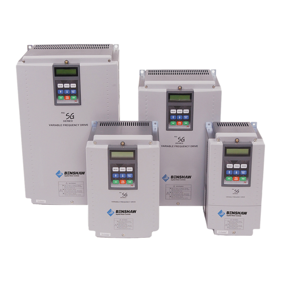
RSi SG Series
Sensorless Vector
Variable Frequency Drive
7.5 to 40HP - 230V
7.5 to 700HP - 460V
7.5 to 150HP - 600V
Instruction Manual
Advertisement
Table of Contents
Troubleshooting

Subscribe to Our Youtube Channel
Related Manuals for BENSHAW RSi SG Series


Summary of Contents for BENSHAW RSi SG Series
- Page 1 7.5 to 150HP - 600V Instruction Manual 890046-00-01 © 2012 Benshaw Inc. Benshaw retains the right to change specifications and illustrations in text without prior notification. The contents of this document may not be copied without the explicit permission of Benshaw.
- Page 2 TRADEMARK NOTICE Benshaw and are registered trademarks of Benshaw Incorporated. Modbus is a registered trademark of Schneider Electric. UL is a trademark of Underwriters Laboratories, Incorporated.
- Page 3 SAFETY INSTRUCTIONS To prevent injury and property damage, follow these instructions during the installation and operation of the drive. Incorrect operation due to ignoring these instructions may cause harm or damage. The following symbols are used throughout the manual to highlight important information.
- Page 4 WARNING Do not remove the cover while power is applied or the unit is in operation. Do not operate the drive with the front cover removed. Electric shock can occur due to the exposed terminals and bus bars. ...
- Page 5 - Incorrect terminal wiring could result in drive and/or equipment damage. - Reversing the polarity (+/-) of the Px and N terminals could damage the drive. - Only authorized personnel familiar with Benshaw drives should perform wiring and inspections. (3) Trial run - Check all parameters during operation.
- Page 6 (4) Operation precautions - When the Auto restart function is selected the drive will restart after a fault has occurred. - The Stop key on the keypad is always active regardless of drive control (start/stop) methods set in parameters DRV-03 and DRV-91. - If Restart after Fault Reset (AFN-21) is set to “yes”, and a fault reset is made with the run command and/or reference signal present, a sudden start will occur.
-
Page 7: Table Of Contents
Table of Contents CHAPTER 1. BASIC INFORMATION 1.1 SING ANUAL 1.2 ENERAL NFORMATION 1.3 ONTACTING ENSHAW URTISS RIGHT ONTROL 1.4 NSPECTION 1.4.1 Drive Model Number 1.4.2 Installation 1.4.3 Wiring 1.5 ECOMMENDED NSTALLATION CHAPTER 2. DRIVE RATINGS AND SPECIFICATION 2.1 230V (7.5~40 HP) ATINGS 2.2 ... - Page 8 Table of Contents (continued) CHAPTER 5. PARAMETER LIST 5-1 5.1 DRV (D 5-1 RIVE ROUP ARAMETER 5.2 FUN (F 5-3 UNCTION ROUP ARAMETER 5.3 AFN (A 5-6 DVANCED UNCTION ROUP ARAMETER 5.4 I/O (I 5-10 NPUT UTPUT ROUP ARAMETER 5.5 APP (A 5-16 ...
- Page 9 Table of Contents (continued) CHAPTER 9. RS485/MODBUS-RTU COMMUNICATION 9-1 9.1 9-1 NTRODUCTION 9.1.1 Features 9-1 9.1.2 Connection Guide for Modbus-RTU Communication with PC, PLC and RS232/485 9-1 9.1.3 Before Installation 9-1 9.2 9-2 PECIFICATION 9.2.1 Performance Specification 9-2 9.2.2 Hardware Specification 9-2 ...
-
Page 11: Chapter 1. Basic Information
NOTE: Information about products and services is available by contacting Benshaw. Refer to section 1.3, Contacting Benshaw. Start-Up Services Benshaw technical field support personnel are available to do startup and conduct on-site training on the drive operations and troubleshooting. On-Site Training Services Benshaw technical field support personnel are available to conduct on-site training on the operations and troubleshooting. -
Page 12: Contacting Benshaw/Curtiss Wright Flow Control Co
Visit the Curtiss Wright / Benshaw website: http://www.benshaw.cwfc.com Technical support for the SG Series drive is available at no charge by contacting Benshaw’s customer service department at one of the above telephone numbers. A service technician is available Monday through Friday from 8:00 a.m. -
Page 13: Inspection
Remove the drive from its packing and inspect its exterior for shipping damage. If damage is apparent notify the Shipping agent and your Benshaw sales representative. Remove the cover and inspect the drive for any apparent damage or foreign objects. Ensure that all mounting hardware and terminal connection hardware is properly seated, securely fastened, and undamaged. -
Page 14: Recommended Installation
Chapter 1 – Basic Information 1.5 Recommended Installation ❶ Use a grounded power source with a voltage within the AC Source permissible range of drive input voltage rating. Ungrounded ❶ Supply power sources will cause nuisance tripping and/or damage to the drive. -
Page 15: Chapter 2. Drive Ratings And Specification
Chapter 2. Drive Ratings and Specification 2.1 Ratings 230V (7.5~40 HP) RSi___SG-2B Std. Duty VT [HP] Motor Rating [kW] 18.5 Std. Duty CT [HP] Motor Rating [kW] 18.5 Heavy Duty [HP] CT Motor [kW] 18.5 Rating Output Frequency 0.01 ~ 120 Hz Rating Voltage 200 ~ 240 V Input Voltage 3... -
Page 16: Ratings 460V (50~125Hp)
Chapter 2 – Drive Ratings and Specification 2.3 Ratings 460V (50~125HP) RSi___SG-4B Std. Duty [HP] VT Motor [kW] Rating Std. Duty [HP] CT Motor [kW] Rating Heavy Duty [HP] CT Motor [kW] Rating Output Frequency 0.01 ~ 120 Hz Rating Voltage 380 ~ 480 V Input Voltage 3... -
Page 17: Ratings 575V (7.5~40Hp)
Chapter 2 – Drive Ratings and Specification 2.5 Ratings 575V (7.5~40HP) RSi___SG-6B Std. Duty [HP] VT Motor [kW] 18.5 Rating Std. Duty [HP] CT Motor [kW] 18.5 Rating 15.5 24.7 Heavy Duty [HP] CT Motor [kW] 18.5 Rating 19.8 31.5 Output Frequency 0.01 ~ 120 Hz Rating Voltage... -
Page 18: Ratings 575V (150 ~ 400 Hp)
Chapter 2 – Drive Ratings and Specification 2.7 Ratings 575V (150 ~ 400 HP) RSi___SG-6 Std. Duty VT [HP] Motor Rating [kW] Std. Duty CT [HP] Motor Rating [kW] Heavy Duty CT [HP] Motor Rating [kW] Output Frequency 0.01 ~ 120 Hz rating Voltage 525 ~ 600 V Voltage 3... -
Page 19: General Specification
Chapter 2 – Drive Ratings and Specification 2.8 General Specification Cooling method Forced air cooling 100KA, Suitable for use on a circuit capable of delivering not more than 100,000 Short Circuit Rating A(rms) Symmetrical amperes when protected by a breaker or fuse with an interrupt rating of not less than 100,000 A(rms). - Page 20 Chapter 2 – Drive Ratings and Specification General Specification (continued) Over Voltage, Low Voltage, Over Current, Ground Fault, Inverter Overheat, Motor Overheat, Output Phase Open, Overload Protection, External Fault 1, 2, Inverter Trips Communication Error, Loss of Speed Command, Hardware Fault, Option Fault Inverter Alarms Stall Prevention, Overload Alarm, Over Heat, Thermal Sensor Fault Below 8.3 msec: Continuous operation...
-
Page 21: Dimensions
Chapter 2 – Drive Ratings and Specification 2.9 Dimensions 1) 7.5 HP, 230V 7.5 HP, 460V 5.91 [150.01] 0.39 5.12 6.16 [10.01] [130.00] [156.49] 0.30 0.71 DIA. [7.49] MTG. HOLES (2 PLACES) 11.18 REMOVABLE SG 11.18 [284.00] LCD KEYPAD [284.00] 10.59 10.59 VARIABLE FREQUENCY DRIVE [269.01] [269.01] WARNING... - Page 22 Chapter 2 – Drive Ratings and Specification 2) 10 HP ~ 15 HP, 230V 10 HP ~ 15 HP, 460V 7.87 [200.00] 7.09 0.39 7.17 [180.01] [10.01] [181.99] 0.30 0.71 DIA. [7.49] MTG. HOLES (2 PLACES) 11.18 REMOVABLE SG 11.18 [284.00] LCD KEYPAD [284.00] 10.59 10.59 VARIABLE FREQUENCY DRIVE [269.01] [269.01] WARNING WARNING...
- Page 23 Chapter 2 – Drive Ratings and Specification 3) 7.5 HP ~ 15 HP, 600V 7.87 [200.00] 0.39 7.09 7.19 [10.01] [180.01] [182.50] 0.33 0.71 DIA. [8.48] MTG. HOLES (2 PLACES) REMOVABLE SG 13.98 13.98 LCD KEYPAD [354.99] [354.99] VARIABLE FREQUENCY DRIVE 13.39 13.39 [340.00] [340.00] WARNING Risk of Injury or Electric Shock Risk of Electric Shock...
- Page 24 Chapter 2 – Drive Ratings and Specification 4) 20 HP ~ 25 HP, 230V 20 HP ~ 25 HP, 460V 20 HP ~ 25 HP, 600V 9.84 [250.01] 9.06 0.39 7.91 0.71 DIA. [230.00] [10.01] [200.86] 0.30 MTG. HOLES [7.49] REMOVABLE SG (2 PLACES) LCD KEYPAD 15.16 17.89 [384.99] [454.28] 14.57 17.89 VARIABLE FREQUENCY DRIVE VARIABLE FREQUENCY DRIVE [370.00] 15.16...
- Page 25 Chapter 2 – Drive Ratings and Specification 5) 30 HP ~ 40 HP, 230V 30 HP ~ 40 HP, 460V 30 HP ~ 40 HP, 600V 11.97 [304.01] 11.18 0.39 9.22 0.71 DIA. [284.00] [10.01] [234.19] 0.30 MTG. HOLES [7.49] REMOVABLE SG (2 PLACES) LCD KEYPAD 18.11 18.11 [459.99] [459.99] VARIABLE FREQUENCY DRIVE 17.52 23.59 [445.01] 17.52 [599.21]...
- Page 26 Chapter 2 – Drive Ratings and Specification 6) 50 HP ~ 60 HP, 460V 11.81 [299.97] 0.35 DIA. 7.48 2.17 10.46 MTG. HOLES [189.99] [54.99] [265.68] 0.37 (2 PLACES) [9.40] REMOVABLE SG LCD KEYPAD 21.02 21.02 [533.91] [533.91] 20.28 VARIABLE FREQUENCY DRIVE 20.28 [515.11] [515.11] 25.28 WARNING...
- Page 27 Chapter 2 – Drive Ratings and Specification 7) 75 HP, 460V 11.81 [299.97] 0.35 DIA. 7.48 11.52 MTG. HOLES [189.99] [292.61] (2 PLACES) REMOVABLE SG LCD KEYPAD 21.02 21.02 [533.91] [533.91] 20.28 VARIABLE FREQUENCY DRIVE 20.28 [515.11] 25.28 [515.11] 25.28 WARNING WARNING [642.01] [642.01] 5.12...
- Page 28 Chapter 2 – Drive Ratings and Specification 8) 50 HP ~ 75 HP, 600V 11.81 [299.97] 0.35 DIA. 7.48 2.17 11.52 MTG. HOLES [189.99] [54.99] [292.61] 0.37 (2 PLACES) [9.40] REMOVABLE SG LCD KEYPAD 21.02 [533.91] 21.02 [533.91] 20.28 25.28 25.28 [515.11] [642.01] [642.01] VARIABLE FREQUENCY DRIVE 20.28 [515.11] WARNING...
- Page 29 Chapter 2 – Drive Ratings and Specification 9) 100 HP ~ 125 HP, 460V 100 HP ~ 125 HP, 600V 14.57 [370.00] O.86 DIA. KNOCKOUT HOLES (5 PLACES) 14.57 2.56 9.45 [370.00] [65.00] [239.98] 2.99 DIA. KNOCKOUT HOLES (3 PLACES) 7.23 [183.59] 13.29 12.03 13.29 [337.57] [337.57] [305.46] 8.80 6.15 [223.52] [156.26]...
- Page 30 Chapter 2 – Drive Ratings and Specification 10) 150 HP ~ 200 HP, 460V 150 HP, 600V 20.08 20.08 [510.03] [510.03] 16.64 16.64 [422.61] [422.61] TOP VIEW BOTTOM VIEW 20.08 [510.03] 2.55 15.00 16.64 [64.77] [381.08] [422.63] 0.43 DIA. MTG. HOLES (2 PLACES) REMOVABLE SG LCD KEYPAD 30.85 30.85 [783.59]...
- Page 31 Chapter 2 – Drive Ratings and Specification 11) 250 HP, 460V 200 HP ~ 250 HP, 600V 20.08 20.08 [510.03] [510.03] 16.64 16.64 [422.61] [422.61] TOP VIEW BOTTOM VIEW 20.08 [510.03] 2.55 15.00 16.64 [64.77] [381.08] [422.63] 0.43 DIA. MTG. HOLES (2 PLACES) REMOVABLE SG LCD KEYPAD 33.90 33.90 [861.01]...
- Page 32 Chapter 2 – Drive Ratings and Specification 12) 350 HP ~ 400 HP, 460V 350 HP ~ 400 HP, 600V 27.17 27.17 [690.12] [690.12] 17.70 17.70 [449.61] [449.61] TOP VIEW BOTTOM VIEW 27.17 [690.12] 2.15 11.43 11.43 17.70 [54.64] [290.42] [290.42] [449.61] 0.43 DIA. MTG. HOLES (2 PLACES) REMOVABLE SG LCD KEYPAD 42.44 42.44...
- Page 33 Chapter 2 – Drive Ratings and Specification 13) 500 HP, 460V 30.39 30.39 [771.91] [771.91] 17.40 17.40 [441.99] [441.99] TOP VIEW BOTTOM VIEW 30.39 [771.91] 9.85 9.85 17.40 [250.09] [250.09] [442.01] 0.43 DIA. MTG. HOLES (2 PLACES) REMOVABLE SG LCD KEYPAD 44.90 44.90 [1140.36] [1140.46]...
- Page 34 Chapter 2 – Drive Ratings and Specification 14) 600 HP ~ 700 HP, 460V 36.30 36.30 [922.02] [922.02] 19.49 19.49 [495.00] [495.00] TOP VIEW BOTTOM VIEW 36.30 [922.02] 6.73 11.42 11.42 19.49 [171.04] [289.97] [289.97] [495.00] 0.51 DIA. MTG. HOLES (3 PLACES) REMOVABLE SG LCD KEYPAD 51.25 51.28 [1301.83]...
- Page 35 Notes :...
-
Page 37: Chapter 3. Installation
Chapter 3. Installation 3.1 Installation Precautions 1) Handle the drive with care to prevent damage to the plastic components. Do not hold the drive by the front cover. 2) Do not mount the drive in a location where excessive vibration (5.9 m/sec or less) is present such as installing the drive on a press or other moving equipment. - Page 38 Chapter 3 - Installation 6) Do not mount the drive in direct sunlight or near other heat sources. 7) The drive shall be mounted in a Pollution Class 2 environment. If the drive is going to be installed in an environment with a high probability of dust, metallic particles, mists, corrosive gases, or other contaminates, the drive must be located inside the appropriate electrical enclosure of the proper NEMA or IP rating.
-
Page 39: Wiring
Chapter 3 - Installation 3.2 Wiring 3.2.1 Basic Wiring 1) For 7.5~40 HP (5.5~30kW) Dynamic Main Power Circuit Braking Unit DB Unit(Optional) (Optional) DB Resistor DC Bus Choke (Optional ) (Optional) N B1 B2 DC Bus Choke DB Resistor P1(+) P2(+) N(-) MCCB(Option) ... - Page 40 Chapter 3 - Installation 2) For 50~125HP (37~90KW) and 500~700HP (315~450kW) Main Power Circuit Dynamic Braking Unit DB Unit(Optional) (Optional) DB Resistor DC Bus Choke (Optional ) (Optional) N B1 B2 DC Bus Choke DB Resistor P1(+) P2(+) N(-) MCCB(Option) ...
- Page 41 Chapter 3 - Installation 3) For 150~400HP (110~280kW) Main Power Circuit Dynamic Braking Unit DB Unit(Optional) (Optional) DB Resistor (Optional) P N B1 B2 DB Resistor P2(+) N(-) DC Reactor(Built-in R(L1) MOTOR S(L2) AC Input T(L3) 50/60 Hz Control Circuit Analog Power Source (+12V) Programmable Digital Input 1(Speed L) Frequency reference (0~12V,V1S : -12~12V)
- Page 42 Chapter 3 - Installation 4) Power Terminals: Screw Terminals 7.5 ~ 40 HP (230V/460V/575V) R(L1) S(L2) T(L3) P1(+) P2(+) N(-) Jumper Bus Bar Terminals 50 ~ 125 HP (460V/575V) / 500 ~ 700 HP (460V) R(L1) S(L2) T(L3) P1(+) P2(+) N(-) Jumper Bus Bar Terminals...
- Page 43 Chapter 3 - Installation 5) Control circuit terminal 7.5 ~ 40 HP (230V/460V/575V) C+ CM C- M6 24 M7 M8 A0 B0 5G 5G S0 S1 3A 3C 3B A1 C1 A2 C2 A3 C3 A4 C4 M1CMM2 M3 24 M4 M5 V+ V1 5G V- I NT 50 ~ 700 HP (460V), 50 ~ 150 HP (575V) C+ CM C- M6 24 M7 M8...
- Page 44 Chapter 3 - Installation Type Symbol Name Description Multi-Function Defines Multi-Function Inputs. M1, M2, M3 Input 1, 2, 3 (Factory setting: Multi-Step Frequency 1, 2, 3) Forward Run FX [M7] Forward Run When Closed and Stopped When Open. Command Reverse Run RX [M8] Reverse Run When Closed and Stopped When Open.
-
Page 45: Wiring Input And Output Power Terminals
Chapter 3 - Installation 3.2.2 Wiring Input and Output Power Terminals General Power Wiring Precautions 1) The internal circuits of the drive will be damaged if the incoming power is connected and applied to the output terminals (U, V, W). If a drive bypass contactor is used, extreme care must be taken so that input voltage is never applied to the output terminals. - Page 46 A filter may be required to be added to the output of the drive depending on the lead lengths from the drive to the motor. Contact Benshaw for assistance with selecting the appropriate filter. See the table below. PWM Carrier Frequency...
-
Page 47: Interference Suppression Measures
Chapter 3 - Installation If an output filter is used it is recommended that the output filter is wired as follows: U,V,W Motor Drive Within 16.4ft Per Table - Wiring distance from drive output to filter input should not exceed 5 meters (16.4 feet). - Wiring distance from filter to motor should not exceed the distance in the preceding table. - Page 48 Chapter 3 - Installation - Use a shielded motor cable that is grounded over a large surface area at both ends. The shield on this cable should be uninterrupted. If a shielded motor cable cannot be used, the unshielded motor lines should be laid in a metal conduit or duct which is uninterrupted and grounded at both ends.
-
Page 49: Terminal Layout
Chapter 3 - Installation 3.2.4 Terminal Layout Screw Terminals 7.5 ~ 40 HP (230V/460V/575V) R(L1) S(L2) T(L3) P1(+) P2(+) N(-) Jumper Bus Bar Terminals 50 ~ 125 HP (460V/575V) / 500 ~ 700 HP (460V) R(L1) S(L2) T(L3) P1(+) P2(+) N(-) Jumper Bus Bar Terminals 150 ~ 400 HP (460V/575V) -
Page 50: Wire Sizing And Terminal Lugs
Chapter 3 - Installation 3.2.5 Wire Sizing and Terminal Lugs The input power and motor cables must be of the appropriate type and dimensioned according to applicable national and local (NEC, etc.) regulations to carry the rated current of the drive. It is recommended that the cables be at least the size listed below in the following table. -
Page 51: Control Circuit Wiring
Chapter 3 - Installation 3.2.6 Control Circuit Wiring (1) Wiring Precautions CM and 5G terminals are isolated from each other. Digital Input Terminals are rated 24 VDC. Do not apply 120 Vac directly to control circuit input terminals. Use shielded wires or twisted wires for all control circuit wiring, and separate these wires from the main power circuits and other high voltage circuits (such as 120V relay circuits). - Page 52 Chapter 3 - Installation (3) Control circuit operation RSI-SG provides NPN/PNP modes for activating the input terminals on the control board. Each connection method is described below. Method 1: NPN mode, Mx – CM NPN mode: when J1 switch is set to NPN mode (downward), use Mx to CM for connection of an external contact (switch, relay or transistor).
- Page 53 Chapter 3 - Installation Method 2: PNP mode, 24V – Mx PNP mode (Internal P/S used): when J1 switch is set to PNP mode (upward), use 24V to Mx for connection of an external contact (switch, relay or transistor). With contact closed, the control board input terminal is activated (turned ON) using the internal 24V power supply.
-
Page 54: Rs-485/Modbus-Rtu Circuit Wiring
Chapter 3 - Installation Method 3: External 24V – Mx PNP mode (External P/S used): when J1 switch is set to PNP mode (upward), use an external 24V to Mx for connection of a contact (switch, relay or transistor). With contact closed, the control board input terminal is activated (turned ON). -
Page 55: Keypad Wiring
Chapter 3 - Installation 3.2.8 Keypad Wiring The keypad connects to the control board at the keypad connector (CN2). Keypad Connector (CN2) 3-19... - Page 56 Notes :...
-
Page 57: Chapter 4. Operation
Chapter 4. Operation 4.1 Keypad Programming 4.1.1 LCD Keypad The RSi SG drive LCD keypad can display up to 32 alphanumeric characters. Drive status can be checked directly from the display and parameter values can be adjusted. The following is an illustration of the keypad. The Program Button is used to go into 32 character, background... -
Page 58: Detailed Description
Chapter 4 - Operation 4.1.2 Detailed Description 3) Frequency Setting Source 2) Run/Stop Source LCD Keypad Display 1) Parameter group 4) Output Current ► D R V T / K 0 . 0 S T P 0 . 0 0 5) Parameter Number 7) Drive Output Frequency During Run, Command Frequency During Stop 6) Operating Status... -
Page 59: Parameter Setting And Adjustment
Chapter 4 - Operation 4.1.3 Parameter Setting and Adjustment 1) Press [MODE] key until the desired parameter group is displayed. 2) Press [▲] or [▼] keys to move to the desired parameter number. If you know the desired parameter number, you can program the parameter number within each parameter group in “Jump code”, except DRV group. 3) Press [PROG] key to go into the programming mode, the cursor starts blinking. -
Page 60: Parameter Groups
Chapter 4 - Operation 4.1.4 Parameter Groups The SG series drive has 5 parameter groups separated according to their applications as indicated in the following table. Parameter Description LCD Keypad Group Command Frequency, Accel/Decel Time etc. Drive Group Basic function Parameters Max. - Page 61 Chapter 4 - Operation Parameter Navigation: Pressing the [SHIFT] key at any time moves directly to the main screen of the DRV group. Pressing the [MODE] key moves forward through the groups. Pressing the [ENTER] key moves reverse through the groups. Drive Group FUN Group AFN Group...
-
Page 62: Easy Start Operation
Chapter 4 - Operation 4.1.5 Easy Start Operation Easy Start Operation is activated by pressing STOP key on the Keypad for 2~3 seconds and the drive begins operation via Keypad (FWD/REV RUN/STOP). Drive mode is preset to V/F and reference frequency to JOG (default 10 Hz.). -
Page 63: Quickstart 2: Two Wire Start And Control Via Speed Potentiometer
Chapter 4 - Operation 4.1.7 Quickstart 2: Two Wire Start and Control via Speed Potentiometer Description: The following example shows how to configure the drive to operate from a speed potentiometer and a remote two wire start command. If a three-wire start/stop circuit is required refer to I/O 20 – 29. One of the inputs can be configured to 3-wire. [Wiring] INPUT M8(RX) -
Page 64: Quickstart 3: Two Wire Start And Control Via 4-20Ma Analog Input
Chapter 4 - Operation 4.1.8 Quickstart 3: Two Wire Start and Control via 4‐20mA Analog Input Description: The following example shows how to configure the drive to operate from a 4-20mA analog input and a remote two wire start command. If a three-wire start/stop circuit is required refer to I/O 20 – 29. One of the inputs can be configured to 3-wire. [Wiring] INPUT M8(RX) - Page 65 Notes :...
- Page 67 Chapter 5. Parameter List 5.1 DRV (Drive Group) Parameter List [DRV Group] Adj. LCD Keypad Factory During PARAM Description Display Setting Range Default Page DRV-00 0 - (FUN-30) DRV>K/K 0.0 A Main Display (Notes 1 & 2) 0.50Hz. 7.5~125HP Acc. time 0 - 6000 secs. DRV-01 Acceleration Time 150~700HP 0 - 6000 secs.
- Page 68 Chapter 5 – Parameter List Adj. LCD Keypad Factory During PARAM Description Display Setting Range Default Page Ia= 0A Ib= 0A DRV-24 Output Current View Only Ic= 0A It = 0A Minimum Last Spd DRV-26 Keypad Reference Mode Preset Spd 1 Disable KeyRefMode Stop...
-
Page 69: Fun (Function Group) Parameter List
Chapter 5 – Parameter List 5.2 FUN (Function Group) Parameter List [FUN GROUP] Adj. LCD Keypad Factory During PARAM Description Display Setting Range Default Page Jump Code – Program, a specific parameter FUN-00 Jump Code 0 - 74 #, hit enter to jump to that parameter. None FUN-01 Run Prevention... - Page 70 Chapter 5 – Parameter List Adj. LCD Keypad Factory During PARAM Description Display Setting Range Default Page FUN-44 User V/F – Voltage 2 User volt 2 0 - 100 % FUN-45 User V/F – Frequency 3 User Freq 3 0 - FUN-30 45.00 FUN-46 User V/F –...
- Page 71 Chapter 5 – Parameter List Adj. LCD Keypad Factory During PARAM Description Display Setting Range Default Page The gray-highlighted parameters are hidden parameters and will appear when the related functions are set. Note 7: FUN-04and FUN-05 only displayed when FUN-03 is set to “S-Curve”. Note 8: FUN-11 and FUN-12 only displayed when FUN-10 is set to “yes”.
-
Page 72: Afn (Advanced Function Group) Parameter List
Chapter 5 – Parameter List 5.3 AFN (Advanced Function Group) Parameter List [AFN GROUP] Adj. LCD Keypad Factory During PARAM Description Display Setting Range Default Page Jump Code – Program specific parameter #, hit AFN-00 Jump code 1 - 95 6-25 enter to jump to that parameter. - Page 73 Chapter 5 – Parameter List Adj. LCD Keypad Factory During PARAM Description Display Setting Range Default Page Depending 7.5HP ~ 700HP AFN-40 Rated Motor Selection Motor select on the 6-29 inverter capacity * A motor rating same as inverter capacity is automatically set. If different, set the correct value. AFN-41 Number of Motor Poles Pole number...
- Page 74 0 - 12 6-36 PowerOn disp Voltage AFN-81 User Display Selection User disp Voltage 6-36 Watt AFN-82 Software Version iP5A Benshaw Ver 1.0 Ver X.XX View Only 6-36 AFN-83 Last Trip Time LastTripTime X:XX:XX:XX:XX:X View Only AFN-84 Power On Time On-time...
- Page 75 Chapter 5 – Parameter List Adj. LCD Keypad Factory During PARAM Description Display Setting Range Default Page The gray-highlighted parameters are hidden parameters and will appear when the related functions are set. Note 19: AFN-08 is only displayed when AFN-07 is set to ≥1 sec. Note 20: AFN-11 through AFN-16 are only displayed when AFN-10 is set to ‘Yes’.
-
Page 76: I/O (Input/Output Group) Parameter List
Chapter 5 – Parameter List 5.4 I/O (Input/Output Group) Parameter List [I/O GROUP] Adj. LCD Keypad Factory During PARAM Description Display Setting Range Default Page Jump Code – Program a specific parameter #, hit I/O-00 Jump code 1 - 98 6-39 enter to jump to that parameter I/O-01 Filtering Time Constant for... - Page 77 Chapter 5 – Parameter List Adj. LCD Keypad Factory During PARAM Description Display Setting Range Default Page None Operating selection at Loss Free Run I/O-18 Lost command None of Freq. Reference Stop 6-42 Protection Waiting Time after Loss of I/O-19 Time out 0.1 - 120 sec Freq.
- Page 78 Chapter 5 – Parameter List Adj. LCD Keypad Factory During PARAM Description Display Setting Range Default Page Multi-function Input I/O-21 M2 define Same as I/O-20 Speed-M Terminal ‘M2’ Define Multi-function Input I/O-22 Same as I/O-20 Speed-H M3 define Terminal ‘M3’ Define Multi-function Input I/O-23 M4 define...
- Page 79 Chapter 5 – Parameter List Adj. LCD Keypad Factory During PARAM Description Display Setting Range Default Page I/O-57 Deceleration Time 4 Dec time-4 0 - 6000 sec I/O-58 Acceleration Time 5 Acc time-5 0 - 6000 sec I/O-59 Deceleration Time 5 Dec time-5 0 - 6000 sec I/O-60...
- Page 80 Chapter 5 – Parameter List COMM line SpeedSearch Ready I/O-76 Multi-Function Auxiliary 6-51 Contact Output A1-C1 (con’t) OH Warn (con’t) FAN Signal RMT Status Multi-Function Auxiliary I/O-77 Same as I/O-76 NONE Aux mode2 Contact Output A2-C2 Multi-Function Auxiliary 6-51 I/O-78 Same as I/O-76 NONE Aux mode3...
- Page 81 Chapter 5 – Parameter List Adj. LCD Keypad Factory During PARAM Description Display Setting Range Default Page I/O-90 Inverter Number Inv No. 1 - 250 1200 bps 2400 bps 4800 bps 6-57 I/O-91 Baud Rate Selection 9600 Baud rate 9600 bps 19200 bps 38400 bps None...
-
Page 82: App (Application Group) Parameter List
Chapter 5 – Parameter List 5.5 APP (Application Group) Parameter List [APP GROUP] Adj. LCD Keypad Factory During PARAM Description Display Setting Range Default Page Jump Code – Program a specific parameter #, hit APP-00 Jump code 1 1 ~ 97 6-61 enter to jump to that parameter APP-01 Application Mode... - Page 83 Chapter 5 – Parameter List Adj. LCD Keypad Factory During PARAM Description Display Setting Range Default Page APP-21 2nd Deceleration Time 2nd Dec time 0 6000 sec APP-22 2nd Base Frequency 2nd BaseFreq 30 - FUN-30 Hz 6-68 Linear APP-23 2nd V/F Pattern 2nd V/F Square...
- Page 84 Chapter 5 – Parameter List Adj. LCD Keypad Factory During PARAM Description Display Setting Range Default Page Delay Time before APP-59 Aux stop DT 0.0 - 999.9 sec 6-71 Stopping Aux Motor Accel time when the APP-60 Pid AccTime 0 - 600.0 sec 6-71 number of pump decreases Decel time when the...
- Page 85 Chapter 5 – Parameter List Adj. LCD Keypad Factory During PARAM Description Display Setting Range Default Page Ext PID Feedback Signal APP-83 Ext Fbk Sel 6-77 Selection Pulse APP-85 P Gain for ExtPID ExtPID Pgain 0 - 999.9 % 1.00 6-77 APP-86 I Time for ExtPID...
-
Page 86: Ext (4-20Ma Output Option Card) Parameter List
Chapter 5 – Parameter List 5.6 EXT (4‐20mA Output Option Card) Parameter List [EXT GROUP] Adj. LCD Keypad Factory During PARAM Description Display Setting Range Default Page Jump Code – Jump directly to any parameter by EXT-00 1 - 45 Jump code programming the desired parameter # EXT-01 View Type of Option Board... - Page 87 Notes...
-
Page 89: Chapter 6. Parameter Descriptions
Chapter 6. Parameter Descriptions 6.1 Drive Group [DRV] frequency in FUN-30 to 0Hz when a stop command is DRV-00: Command Frequency / Output Current given. DRV► T/K 0.0A When FUN-73 is set to “Delta Frequency”, the STP 0.00 Hz acceleration and deceleration time is the time taken to reach a target frequency (instead of the maximum Factory Default: 0.00 Hz... - Page 90 Chapter 6 - Parameter Description [DRV] DRV-04: Frequency Mode Description Setting Range Set APP-80 [Ext PI Mode] to DRV► Freq mode “Yes.” Apply Ext. PID feedback Keypad-1 value “4~20mA” control terminal “I”. Set one of the I/O- Factory Default: Keypad-1 20~27 to [Ext PID Run].
- Page 91 Chapter 6 - Parameter Description [DRV] DRV► ETH select DRV► ETH cont Yes --- 100 % Factory Default: Factory Default: 100 % This parameter activates the ETH function when set to ‘Yes’. ETH level is set as the percentage of DRV-05 This is the current at which the motor can run [Motor rated current].
- Page 92 Chapter 6 - Parameter Description [DRV] DRV-12: User Display Selection The speed factor for operation below 20Hz is: DRV► User disp Speed_Factor = (1.5 %/Hz * drive frequency (Hz) + 65%) / 100% 0.0 V Factory Default: 0.0 V Output Current Forced-Cool This parameter displays the value of the parameter 100%...
- Page 93 Chapter 6 - Parameter Description [DRV] DRV-15: Target/Output Frequency Display Note: Certain Hardware faults such as: WDOG error, EEP error, Input Phase Open, Fan Lock, Blown Fuse, NTC Open and ADC Offset cannot be DRV►TAR 0.00Hz 15 OUT 0.00Hz reset until the fault condition is corrected. The drive will not reset when a H/W fault occurs.
- Page 94 Chapter 6 - Parameter Description [DRV] DRV-17: Hz/Rpm Display DRV-20: EXT-PID Parameter (To monitor ExtPID controller’s reference/ feedback/ output value) DRV► Hz/Rpm Disp Displays ExtPID controller’s reference/ feedback/ 0 Hz output value. When APP-80 [Ext. PID operation selection] is set to Factory Default: 0 Hz “YES,”...
- Page 95 Chapter 6 - Parameter Description [DRV] DRV-24: Output Current DRV-27: Current, Phase U DRV-28: Current, Phase V DRV-29: Current, Phase W This parameter displays the individual phase output DRV-30: Current, Ground currents and the average of all phases as It (total). DRV►...
- Page 96 NOTES:...
-
Page 97: Function Group [Fun]
Chapter 6 - Parameter Description [FUN] 6.2 Function Group [FUN] Description FUN-00: Jump to Desired Parameter Setting Range The shape of the ramp is a straight line. Linear FUN► Jump code (Factory default) The shape of the ramp is curved at the beginning and the end. - Page 98 Chapter 6 - Parameter Description [FUN] FUN-10~12: Pre-heat Output Frequency FUN►Pre-HeatMode Factory Default: Time This function allows the drive to apply low levels of DC current to the motor to prevent moisture from Acc. Pattern Dec. Pattern Accel/Decel Pattern: ‘U-curve’ entering and condensation from occurring inside the motor when stopped.
- Page 99 Chapter 6 - Parameter Description [FUN] FUN-21: Starting DC Magnetizing Time FUN►PreHeatLevel FUN-22: Starting DC Magnetizing Value FUN► DcSt time Factory Default: 0.0 sec FUN-11 [Pre-heat value] is set in percent of motor Factory Default: 0.0 sec rated current. Adjustment range is 1% to 50%. FUN►...
- Page 100 Chapter 6 - Parameter Description [FUN] FUN-23: Stop Mode FUN► Stop mode Output Frequency Decel Factory Default: Decel This parameter sets the stopping method of the drive. Time Output Voltage Description Setting Range The drive stops using the Decel deceleration pattern. The drive stops with DC injection Time braking.
- Page 101 Chapter 6 - Parameter Description [FUN] FUN-24: DC Injection Braking Delay Time The drive will decelerate to the frequency set in FUN- FUN-25: DC Injection Braking Frequency 25. Upon reaching that frequency, the drive will wait FUN-26: DC Injection Braking Time the amount of time set in FUN-24.
- Page 102 Chapter 6 - Parameter Description [FUN] control to a safe stop. See parameters AFN-46 (Load FUN► Base freq Inertia), AFN-52 (Decel Rate) and AFN-53 (Decel 60.00 Hz Percentage) to fine tune the operation of this function. Factory Default: 60.00 Hz Note: This function can only be applied to applications that have a high enough inertia to provide enough stored energy to complete the...
- Page 103 Chapter 6 - Parameter Description [FUN] FUN-33: Frequency Limit Selection FUN-40: Volts/Hz Pattern FUN-34: Low Limit Frequency FUN► V/F pattern FUN-35: High Limit Frequency Linear FUN► Freq limit Factory Default: Linear This is the pattern of voltage/frequency ratio. Select the Factory Default: proper V/F pattern according to the load.
- Page 104 Chapter 6 - Parameter Description [FUN] FUN-41 ~ FUN-48: User V/F Frequency and Voltage FUN-49: AC Input Voltage Adjustment FUN► VAC 460.0V FUN► User freq 1 100.0 % 15.00 Hz Factory Default: 100.0 % Factory Default: 15.00 Hz 230V models display VAC 230.0V (default) FUN►...
- Page 105 Chapter 6 - Parameter Description [FUN] FUN-51 Description Setting Range 110% 110 % None Disabled (Factory setting) Energy save ON by decreasing 100% 100 % Manual the output with the value set in FUN-52. 85 % Auto Energy save ON automatically. Param Name Default...
- Page 106 Chapter 6 - Parameter Description [FUN] FUN-56: Motor temperature FUN-64: Overload Warning Level FUN-65: Overload Warning Time FUN► Motor Temp FUN► OL level 110 % Factory Default: Factory Default: 110 % The Motor temperature (in Celsius) detected by an externally connected thermal sensor is displayed in FUN►...
- Page 107 Chapter 6 - Parameter Description [FUN] FUN-66: Overload Trip Selection FUN-69: Input/Output Phase Loss Protection FUN-67: Overload Trip Level (Bit Set) FUN-68: Overload Trip Delay Time FUN► Trip select FUN► OLT select --- No --- Factory Default: Factory Default: This function will cause the drive to trip upon a phase loss or opening.
- Page 108 Chapter 6 - Parameter Description [FUN] FUN-70: Stall Prevention Mode Note: The actual Acceleration time may extend due FUN-71: Stall Prevention Level to stall prevention during Acceleration. FUN► Stall prev. Note: The drive starts deceleration when a Stop command is applied even while a motor stall state is present.
- Page 109 Chapter 6 - Parameter Description [FUN] FUN-72: Accel/Decel Change Frequency FUN-73: Reference Frequency for Accel/Decel FUN►Acc/Dec ch F FUN►Acc/Dec freq 0.00 Hz Factory Default: Factory Default: 0.00 Hz This parameter determines the reference for the Accel / This function is used to change Accel/Decel ramps at a Decel times.
- Page 110 Chapter 6 - Parameter Description [FUN] FUN-74: Accel/Decel Time Scale FUN-75: Up/Down Save Mode FUN►UpDnSaveMode FUN► Time scale 0.1 sec Factory Default: 0.1 sec FUN-76: Up/Down Save Frequency This parameter is used to change the number of FUN►UpDnSaveFreq significant digits displayed for the Accel and Decel 0.00 Hz parameters.
- Page 111 Chapter 6 - Parameter Description [FUN] FUN-81: Analog Stall Source FUN-82: Current Limit Level FUN► AnaStall Src None FUN►Max Ana Perc 100% When FUN-70 (Stall Mode) is set to “yes” user can select a remote variable source (I, V1, Pulse) to limit current instead of a fixed level (FUN-71).
- Page 112 NOTES: 6-24...
-
Page 113: Advanced Function Group [Afn]
Chapter 6 - Parameter Description [AFN] 6.3 Advanced Function Group [AFN] AFN► Erase trips AFN-00: Jump to Desired Parameter No --- AFN► Jump code Factory Default: This function erases all fault histories of AFN-01 to Factory Default: AFN-05 from memory. However, AFN-83 [Last Trip Time] cannot be reset. Jumping directly to any parameter can be accomplished by programming the desired parameter number. - Page 114 Chapter 6 - Parameter Description [AFN] AFN-10 ~ AFN-16: Frequency Jump Output Frequency Freq. Max AFN► Jump freq AFN-16 --- No --- AFN-15 AFN-14 Factory Default: AFN-13 AFN-12 AFN► jump Lo 1 AFN-11 10.00 Hz Reference Frequency Factory Default: 10.00 Hz Frequency Jump AFN►...
- Page 115 Chapter 6 - Parameter Description [AFN] AFN-20: Power ON Start Selection Note: When setting ‘Power ON Start’ to ‘Yes’, make sure to use appropriate warning notices and AFN►Power-on run safety interlocks to minimize the potential for injury or equipment damage. Factory Default: AFN-21: Restart After a Fault Reset If AFN-20 is set to ‘No’, upon loss of power, the user...
- Page 116 Chapter 6 - Parameter Description [AFN] AFN-22: Restart after Instantaneous Power Failure Input Power Input Power loss AFN-23: Speed Search AFN► IPF Mode Time Motor Speed Factory Default: AFN► estimated SS Time Output Frequency Factory Default: estimated SS This function is used to permit automatic restarting into a spinning motor after an Instantaneous Power Failure.
- Page 117 Chapter 6 - Parameter Description [AFN] AFN-40: Motor Capacity Selection Output Frequency AFN-41: Number of Motor Poles AFN-42: Rated Motor Slip AFN-44: No Load Motor Current AFN-45: Motor Efficiency t: AFN-26 AFN-46: Load Inertia Time If the user does not set these values, the drive will use factory default values.
- Page 118 Chapter 6 - Parameter Description [AFN] AFN► Rated-Slip AFN►Inertia rate 2.34 Hz Factory Default: 2.34 Hz Factory Default: Automatically set according to the motor capacity (AFN-40) This parameter is used by many drive functions such as This is used in ‘Slip Compensation’ control, AFN-60. Sensorless Vector control [AFN-60], Speed Search If you set this value incorrectly, the motor may stall [AFN-22], and Safety Stop [FUN-28].
- Page 119 Chapter 6 - Parameter Description [AFN] AFN-48: Carrier Frequency AFN – 49 Description Setting Range Operation via standard Space AFN►Carrier freq Vector PWM pattern. PWM X.X kHz frequency may be automatically Normal Factory Default: Model Dependent adjusted at low speed for optimal performance.
- Page 120 Chapter 6 - Parameter Description [AFN] AFN-60: Control Mode Selection Param Description Display AFN►Control mode AFN-40 Motor select Select motor capacity AFN-42 Rated-Slip Motor rated slip (Hz) Motor rated current Factory Default: DRV-05 Rated-Curr (rms) Selects the control mode of the drive. Motor no load current AFN-44 Noload-Curr...
- Page 121 Chapter 6 - Parameter Description [AFN] ▣ The drive should only use one set of motor Additional Tuning for Sensorless Vector Control parameters. The drive should not be set to use the ▣ Adjust the AFN–44 [No Load Motor Current second set of motor parameters.
- Page 122 Chapter 6 - Parameter Description [AFN] AFN-64: Pre-excitation Time AFN-65: P Gain for Sensorless Control AFN-66: I Gain for Sensorless Control AFN► PreExTime 1.0 sec AFN► SL P-gain 3000 Factory Default: 1.0 sec Factory Default: 3000 When the start command (FWD or REV) is issued, the SL P-gain is the proportional gain of the speed loop drive will pre-excite the motor automatically for the controller during Sensorless Vector control.
- Page 123 Chapter 6 - Parameter Description [AFN] AFN-67: Manual/Auto Boost Selection This can result in high currents, motor overheating, AFN-68: Torque Boost in Forward Direction and over current trips. AFN-69: Torque Boost in Reverse Direction Auto Torque Boost AFN►Torque boost Manual When AFN-67 [Manual/Auto torque boost select] is set to “Auto”, the drive will increase the torque boost automatically to match the required load.
- Page 124 Chapter 6 - Parameter Description [AFN] AFN-80: Power On Display AFN-82: Software Version AFN►PowerOn disp AFN► S/W Version Ver 1.0 Factory Default: Factory Default: Ver. 1.0 This parameter selects which parameter will be This parameter displays the software version. This will displayed first on the keypad when the power is turned vary depending on software version installed in the drive.
- Page 125 Chapter 6 - Parameter Description [AFN] AFN-87: Output Power Display Adjustment Note: When AFN-91, 92 is used, motor parameters such as DRV-05, AFN-40~46 and AFN-62~63 will be AFN► Power set initialized. 100% Factory Default: 100% 1) Set AFN-91 to “Yes” and press Enter key to read the parameters.
- Page 126 Chapter 6 - Parameter Description [AFN] AFN-93: Parameter Initialize AFN-94: Parameter Lock AFN► Para. init AFN► Para. lock Factory Default: Setting Range: 0 - 9999 This is used to initialize parameters back to the factory This function is used to lock the parameters from being default values.
-
Page 127: Input/Output Group [I/O]
Chapter 6 - Parameter Description [I/O] 6.4 Input/Output Group [I/O] I/O► V1 volt x1 0.00 V I/O-00: Jump to Desired Parameter Factory Default: 0.00 V I/O► Jump code This is the minimum voltage of the V1 input at which the drive will output minimum frequency (I/O-03). Factory Default: I/O►... - Page 128 Chapter 6 - Parameter Description [I/O] I/O-06 ~ I/O-10: Analog Current Input (I) Signal I/O► I curr x2 Adjustment 20.00 mA These parameters are used to adjust the scaling of the Factory Default: 20.00 mA "I" analog input signal. The scaling and slope of the This is the maximum current of the ‘I’...
- Page 129 Chapter 6 - Parameter Description [I/O] I/O-11~16: Frequency command setting via pulse Pulse Specification (A0/B0) Term Setting Range I/O► P pulse set High: +3~+5V Max A0/B0 7.5 ~ 40 Low: +2V Max Max Input Freq.: 100KHz Factory Default: High: +12+15V Max A0/B0 50 ~ 700 Low: +2.5V Max...
- Page 130 Chapter 6 - Parameter Description [I/O] The following table describes the settings in I/O-17. Note: When setting P Pulse Input Min/Max Freq. via motor encoder, set the value for encoder pulse Description per the following example: Setting Range None Disabled. To give 60Hz (1800 rpm) command from 1000 Pulse The drive determines that the encoder:...
- Page 131 Chapter 6 - Parameter Description [I/O] I/O-20~27: Multi-function Input Terminal ‘M1, M2, The following table shows the various functions that M3’, ‘M4’, ‘M5’, ‘M6’, ‘M7’, ‘M8’ Define can be programmed (I/O-20 ~ I/O-27) for terminals M1 through M8. I/O► M1 define Speed-L Description Setting Range...
- Page 132 Chapter 6 - Parameter Description [I/O] I/O-28: Terminal Input Status I/O-30: Jog Frequency I/O► In status I/O► Jog freq 00000000000 10.00 Hz Factory Default: 00000000000 Factory Default: 10.00 Hz This parameter displays the input status of control This parameter sets the jog frequency. terminals M1-M8.
- Page 133 Chapter 6 - Parameter Description [I/O] DRV-04 Data DRV-00 Speed 0 Freq source Step Speed Spd- Spd- Spd- Spd- Keypad-1 Digital Freq Ref Keypad Frequency Parametr Keypad-2 Digital Freq Ref Keypad Analog Freq Ref. Terminal DRV-00 S. Freq-0 (Note 1) (Spd-0) Analog Freq Ref.
- Page 134 Chapter 6 - Parameter Description [I/O] I/O-50~63: 1 Accel/Decel Time Output Frequency Ref. I/O► Acc time-1 Freq. 20.0 sec Factory Default: 20.0 sec Time I/O► Dec time-1 Time Time Time Time Time Time Time Time 20.0 sec Time Factory Default: 20.0 sec Time ...
- Page 135 Chapter 6 - Parameter Description [I/O] Speed Output Freq. [EXCHANGE] Exchange is used to switch the motor from the drive output to line (commercial) power or from line to drive output. To bypass the motor to commercial line, set the ‘Exchange’...
- Page 136 Chapter 6 - Parameter Description [I/O] [Up, Down] [Ext Trip] The speed of the drive can be controlled using two This is a normally open contact input. When a terminal multi-function input terminals. Externally connected set to ‘Ext Trip’ is ON, the drive cuts off its output and momentary switches can increase (Up) or decrease displays an external fault.
- Page 137 Chapter 6 - Parameter Description [I/O] [Analog hold] [Reset] When there is an analog input signal for frequency This function is used as a fault reset terminal when ON. reference and ‘Analog hold’ terminal is ON, drive fixes It requires a momentary contact closure for fault reset. its output frequency regardless of the frequency reference.
- Page 138 Chapter 6 - Parameter Description [I/O] I/O-70~73: S0, S1 terminal select [DC link vtg] The S0/S1 terminal provides an analog output I/O► S0 mode corresponding to the dc link voltage. The output value Frequency is determined by the following formula: Factory Default: Frequency S0/S1 Output Voltage = (DC link voltage/Max.
- Page 139 Chapter 6 - Parameter Description [I/O] I/O-74: FDT (Frequency Detection) Level Description I/O-75: FDT Bandwidth Setting Range Over voltage detection I/O► FDT freq Low voltage detection 30.00 Hz Inverter overheat detection Lost Command Lost command detection Factory Default: 30.00 Hz Inverter running detection Stop Inverter stop detection...
- Page 140 Chapter 6 - Parameter Description [I/O] [FDT-2] [FDT-4] AX-CX is CLOSED when the reference frequency is in AX-CX is CLOSED when the output frequency I/O-75 [FDT Bandwidth] centered on I/O-74 [FDT reaches the FDT frequency. The output is OPENED Frequency], and the output frequency reaches I/O-75 when the output frequency goes below the FDT centered on I/O-74.
- Page 141 Chapter 6 - Parameter Description [I/O] [OL] [Stall] AX-CX is CLOSED when the output current has AX-CX is CLOSED when the drive is in the stall reached the FUN-64 [Overload Warning Level] for the prevention mode. FUN-65 [Overload Warning Time]. Output Current Output Current FUN-71...
- Page 142 Chapter 6 - Parameter Description [I/O] [LV] Speed Search Output Frequency AX-CX is CLOSED when the DC link voltage is below the Low-voltage level. LV Level 200V DC DC Link Voltage 400V DC 500V DC Time FX-CM Time Mx terminal Time ‘Exchange’...
- Page 143 Chapter 6 - Parameter Description [I/O] I/O-80: Fault Output Relay (3A, 3B, 3C) I/O-81: Terminal Output Status I/O► Relay mode I/O► Out status 00000000 Factory Default: Factory Default: 00000000 This parameter determines how the fault relay will This parameter displays the condition of each of the operate during a fault condition and during low voltage outputs.
- Page 144 Chapter 6 - Parameter Description [I/O] I/O-84: Cooling Fan Control Selection I/O-86: User Unit selection (PI Mode only) I/O-87: Units Maximum Value I/O►Fan Con. Sel I/O► Unit Sel Percent Factory Default: PowerOn_Fan Factory Default: Percent (PSI in PI Mode) This parameter determines the operating condition of When PID operation is selected in APP-02, APP-80, or the drives cooling fans.
- Page 145 Chapter 6 - Parameter Description [I/O] Likewise if “V1” is chosen as feedback (APP-06), I/O► COM Lost Cmd parameter APP-32, “meter V max” is the maximum None value of the feedback voltage (default is 10V) Factory Default: None corresponding to the maximum PSI value, I/O-87. Scaling of feedback signal “V1”.
- Page 146 Chapter 6 - Parameter Description [I/O] I/O-95: Normal Open/ Normal Closed select I/O-97: Overheat Trip Selection I/O► OH Trip Sel I/O► In No/NC Set 00000000 Factory Default: 00000000 Factory Default: I/O-98: Motor Trip Temperature The digital inputs, M1, M2, M3, M4, M5, M6, M7, and M8 can be programmed as a NO or a NC contact.
- Page 147 Chapter 6 - Parameter Description [I/O] Specification of External PTC/NTC Thermistor Resistance based Measurable Sensor Resistance by temperature on 25 C Temp range R(T)=[1+A*(Measured temp-25)+B *( Measured temp –25) ][K ] (±5%) 0~125[C] K] A=7.635X10 , B=1.371 X10 2.545 (±5%) See the table below for NTC resistance by temperature. 0~150[C] K] Note : Measurable temp range varies by thermal sensors.
- Page 148 NOTES: 6-60...
-
Page 149: Application Group [App]
Chapter 6 - Parameter Description [APP] 6.5 Application group [APP] APP-02: PID Operation Selection APP-00: Jump to Desired Parameter APP► Proc PI mode APP► Jump code Factory Default: This function can be used for process control. It can Factory Default: control flow, pressure, temperature or other process Jumping directly to any parameter can be variables. - Page 150 Chapter 6 - Parameter Description [APP] [PI control] This control is stable in many systems. If ⑥ Select the maximum value of the feedback signal “D control” is added, it becomes the 3 order system. in APP-31 (default 20 mA for “I”), APP-32 (default In some systems this may lead to system instability.
- Page 151 Chapter 6 - Parameter Description [APP] 6-63...
- Page 152 Chapter 6 - Parameter Description [APP] In general, the PID output becomes the drive’s “Target Freq”. In this case, PID is controlling the whole system and the PID output becomes the target freq of the system and the drive is operating according to Accel/Decel Time. PID control sampling time is 10msec.
- Page 153 Chapter 6 – Parameter Description [APP] DRV-04 Keypad PID Wiring Example DRV-00 Set Point (program) APP-06 I (4-20mA) Feedback Keypad as Set point I/O-26 FX (M7 Fwd Run/Stop) Feed Back as I (4-20mA) I/O-27 RX (M8 as Rev Run/Stop) I/O-20 Open Loop (M1 to disable PI Control) R(L1) Power Supply...
- Page 154 Chapter 6 - Parameter Description [APP] APP-03: PID F Gain APP-06: PID Feedback Signal Selection APP-04: PID Aux. Reference Mode Selection APP-07: P Gain for PID Control APP-05: PID Aux. Reference Selection APP-08: I Time for PID Control APP-09: D Time for PID Control APP►...
- Page 155 Chapter 6 – Parameter Description [APP] APP-10: High Limit Frequency for PID Control APP-15: PID Output Inversion APP-11: Low Limit Frequency for PID Control APP► PID Out Inv. APP► PID limit-H 60.00 Hz Factory Default: Factory Default: 60.00 Hz Parameter APP–15 [Output inversion] sets the PID This is the upper limit frequency at which the output controller’s output polarity.
- Page 156 Chapter 6 - Parameter Description [APP] APP-20 ~ APP-29: 2 Functions APP-31: Meter I Max Value APP-32: Meter V1 Max Value APP►2 Acc time APP-33: Meter P Max Value 5.0 sec APP► meter I max Factory Default: 5.0 sec 20.00 mA APP►2 Dec time APP►...
- Page 157 Chapter 6 – Parameter Description [APP] APP-40~APP-72: MMC Operation Control Sleep function is initiated when demand is low. The drive stops the motor when the motor runs below the Sleep Frequency after the Sleep Delay Time has Multiple Motor Control expired.
- Page 158 Chapter 6 - Parameter Description [APP] Multiple Motor Control Parameters APP► Start freq3 49.99 Hz APP► Aux Mot Run Factory Default: 49.99 Hz Factory Default: APP► Start freq4 49.99 Hz This parameter is a display only parameter and Factory Default: displays how many auxiliary motors are being run by 49.99 Hz MMC control.
- Page 159 Chapter 6 – Parameter Description [APP] APP-58: Delay Time before Starting Aux. Motor APP-62: PID Bypass Selection APP-59: Delay Time before Stopping Aux. Motor APP-60, 61: Accel/Decel time when the number of APP► Regul Bypass pumps is increasing/decreasing Factory Default: APP►...
- Page 160 Chapter 6 - Parameter Description [APP] Steps to use MMC operation B. To easily and effectively use Process PID operation, Pre PID APP-74, 75, 76, 77. A. Set MMC in APP-01 B. Set Process PI to Yes in APP-02 C. To divide the load to the motor equally C.
- Page 161 Chapter 6 – Parameter Description [APP] AUX_EXCH Mode: Auto Change Function is Actual Value applied only to aux. motors. Starting of Auxiliary motors is automatically rotated by the drive in AUX_EXCH Mode to prevent a specific motor from operating more than the other motors. On/Off Wakeup level (APP-65) Time...
- Page 162 Chapter 6 - Parameter Description [APP] Auto Change is accomplished when the following conditions are satisfied: 3 Phase Input The time set in APP-67 is over. R S T The drive output speed (Hz.) is less than the APP-68 K1.1 K2.2 setting.
- Page 163 Chapter 6 – Parameter Description [APP] APP-69: Interlock Selection Aux motor starting condition and output (Pressure, air volume.) adjustment APP► Inter-lock Drive turns Aux motors ON automatically when it is impossible for a main motor to control increased Factory Default: load, causing shortage in flow rate or pressure.
- Page 164 Chapter 6 - Parameter Description [APP] APP-71: Pressure Difference for Aux Motor Start Aux motor stopping condition and output (Pressure, APP-72: Pressure Difference for Aux Motor Stop air volume) adjustment Drive turns off the Aux motors when flow rate or APP►Aux Stt Diff pressure is too high due to decreased load.
- Page 165 Chapter 6 – Parameter Description [APP] APP-80~97: External PID operation APP-76 [Pre PID delay time] Set the time period for Pre PID operation. After this APP► Ext PI Mode time expires, normal PID control begins. APP-77 [Pipe Broken] Factory Default: When enabled (set to “yes”) if the condition of APP- 75 (Pre PID Exit Level) is not met and the delay time Program APP-80 to “yes”...
- Page 166 Chapter 6 - Parameter Description [APP] External PID Parameters APP-80 ~ APP-97 Param Display Default Range 0 (No) APP-80 Ext PI mode 0 (No) 1 (Yes) 0 (I) APP-81 1 (V1) Ext Ref Sel 3 (Key-Pad) 2 (Pulse) 3 (Key-Pad) APP-82 Ext Ref Perc 50.00 [%]...
- Page 167 Chapter 6 - Parameter Description [APP] 6-79...
- Page 168 Chapter 6 - Parameter Description [APP] [ Ext. PID internal block diagram] Multi-function Input Terminal Setting I/O-20~27 (M1~M8) I Term Clear P Gain2 Deviation Target Freq. Ext PID P Gain Scale APP-92 APP-85 Ext PID P Gain APP-86 Ext PID I Gain APP-87 Ext PID D Gain Ext PID P2 Gain...
- Page 169 Chapter 6 – Parameter Description [APP] APP-02 , APP-80 (Dual PID operation) ExtPID can be used in the following three cases; 1) controlling another system independently like an external PID controller 2) using both PID controller in APP-02 and External PID controller 3) using ExtPID output as a drive target frequency.
- Page 170 Chapter 6 - Parameter Description [APP] Case 2: Dual PID block diagram Ext. PI mode APP-93 APP-82 APP-80 Ext. PID F Gain: Ext. PID High LImit Multi- function Input Ext. Ref Perc Feed Foward Freq. Terminal Setting Ext. PID Ref Setting (M1~ M8) APP-88 I/O-20~27...
- Page 171 Chapter 6 – Parameter Description [APP] Case 3: Dual PID block diagram Ext. PI mode APP-93 APP-82 APP- Multi-function Input Ext. PID Ext. PID F Gain: Ext. Ref Perc Terminal Setting High LImit Freq. Feed Foward (M1~M8) Ext. PID Ref Setting Analog Meter Output APP-88 I/O-20~27...
-
Page 173: Chapter 7. Trouble Shooting & Maintenance
Chapter 7. Trouble Shooting & Maintenance 7.1 Fault Display When a fault occurs, the drive turns off its output and displays the fault status in parameter DRV-13. When the fault is reset, it gets stored in the fault history. The last five (5) faults are saved in the fault history (parameters AFN-01 through AFN-05) along with the drive’s speed, status, amps, DC Bus voltage and temperature at the time of the fault. - Page 174 Chapter 7 – Trouble Shooting & Maintenance Protective Description Keypad Display Function The drive turns off its output when the one or more of the output phases Output Phase (U, V, W) is detected open. Open is defined as less than half of AFN- Output Phase Open Open 44, No Load Current.
-
Page 175: Fault Remedy
Chapter 7 – Trouble Shooting & Maintenance 7.2 Fault Remedy Protective Cause Remedy Function 1) Acceleration/Deceleration time is too short compared to the 1) Increase Accel or Decel time. inertial of the load. 2) Increase drive capacity. 2) Load is larger than the drive rating. 3) Operate only after motor has 3) Drive turned output on when the motor is still rotating. - Page 176 E-Stop. Wdog error (CPU fault) Drive internal failure. Contact EEP error (memory fault) Benshaw Customer Service for more H/W Fault ADC Offset (current feedback circuit fault) information. No Motor Connection or Under Current Level setting...
- Page 177 Chapter 7 – Trouble Shooting & Maintenance Protective Cause Remedy Function 125 HP and below, thermistor is internal to IGBT block. Repair is required. NTC Open Internal thermistor has failed open or is disconnected. 150 HP and above, thermistor is heat sink mounted.
-
Page 178: Troubleshooting
Chapter 7 – Trouble Shooting & Maintenance 7.3 Troubleshooting Condition Item to Check 1) Main circuit inspection: - Is the input (line) voltage normal? (Is the LED in the drive lit?) - Is the motor connected correctly? 2) Input signal inspection: - Check the operating signal input to the drive. -
Page 179: How To Check Power Components
Chapter 7 – Trouble Shooting & Maintenance 7.4 How to Check Power Components WARNING Turn the power off and wait until the Main DC Bus Electrolytic Capacitors are discharged to a safe level. The voltage between terminal P1-N (or P2-N) should be less than 30VDC. ... - Page 180 Chapter 7 – Trouble Shooting & Maintenance 1) Diode module and IGBT module check (7.5~ 40HP) DCP+ Charge resistor D2 D3 Electrolytic capacitors D4 D5 D6 Test polarity Check Test polarity Check Module Number value value DCP+ Closed Open DCP+ Open Closed Diode...
- Page 181 Chapter 7 – Trouble Shooting & Maintenance 2) Power Component Check – 50 HP ~ 125 HP Test polarity Test polarity Module Reading Module Reading across DC Bus Fuse Fuse 1 across fuse Closed Fuse 1 indicator Closed Fuse Indicator SCR's P2 (+) Open...
- Page 182 Chapter 7 – Trouble Shooting & Maintenance 3) Power Component Check – 150 HP ~ 250 HP Test polarity Test polarity Module Reading Module Reading Fuse 1 across fuse Closed Fuse 1 across indicator Closed DC Bus Fuse Fuses Indicators across indicator Fuse 2 across fuse...
- Page 183 Chapter 7 – Trouble Shooting & Maintenance 4) Power Component Check – 350 HP ~ 400 HP Test polarity Test polarity Module Reading Module Reading across fuse Fuse 1 Closed Fuse 1 across indicator Closed DC Bus Fuse Fuses Indicators across fuse across indicator Fuse 2...
- Page 184 Chapter 7 – Trouble Shooting & Maintenance 5) Power Component Check – 500 HP ~ 700 HP Test polarity Test polarity Module Reading Module Reading R across fuse Fuse 1 Closed Fuse 1 across indicator Closed Line Fuse Fuses Indicators S across fuse across indicator Fuse 2...
-
Page 185: Maintenance
Chapter 7 – Trouble Shooting & Maintenance 7.5 Maintenance The Benshaw series of drive’s (Models SG, S4 and GX) are an industrial electronic product with advanced semiconductor components. A reasonable life expectancy of 8 to 10 years can be expected. However, there are factors that may affect their continued long term operation. -
Page 186: Periodic Inspection
Chapter 7 – Trouble Shooting & Maintenance 7.5.3 Periodic Inspection Period Customer Inspection Item Inspection Inspection Method Criterion Check/ Initial /Date Temperature: -10~+40C Is the ambient Measure/Monitor Ambient temperature and humidity (Thermometer, Hygrometer, Humidity: Temperature/Humidity adequate? Recorder) Under 90% non- condensing Any signs of physical damage to the enclosure of the drive? -
Page 187: Parts Replacement
7.5.4 Parts Replacement Part name Period Comments Cooling fans 2-3 years Exchange for a new fan after consulting Benshaw customer service center. Electrolytic 5 years Perform periodic inspections every year. capacitors Exchange after testing and consulting Benshaw customer service center. The Recommended capacitance level to... - Page 188 Notes :...
-
Page 189: Chapter 8. Options
Ethernet network. Dynamic Brake Unit See Section 8.1.6 Contact A Brake Unit and a Resistor enables drive to decelerate rapidly and Benshaw for Sizing of Brake Dynamic Brake handle regenerative loads. Units and Brake Resistors resistors Included with drives up to 125... -
Page 190: Lcd Keypad
Chapter 8 – Options 8.1.1 LCD Keypad For Replacement or Remote Mounting - Part # LCD-100000-00 LCD Keypad (Weight: 140 g) 8.1.2 Remote Keypad Cable Part # Description VFD-2M-RE-Cable-SG 2m (6.6ft) Remote cable VFD-3M-RE-Cable-SG 3m (9.9ft) Remote cable VFD-5M-RE-Cable-SG 5m (16.5ft) Remote cable 8.1.3 4 – 20 mA Output Option Card Part # VFD-RSI-SG-4-20-MA, Manual # 890027-11-xx. -
Page 191: Profibus Communications Option Card
In cases where a short stopping time is desired or a high inertia or regenerative load requires dynamic braking capability, an optional Dynamic Braking (DB) unit can be added to the SG drive. Contact Benshaw for more information regarding this option. Dynamic Brake Resistors are NOT included with the DB Unit. - Page 192 Chapter 8 – Options 2) DB Unit Terminal layout Terminals Description Ground terminal Connect to DB Resistor’s B2 Connect to DB Resistor’s B1 Connect to drive terminal N Connect to drive terminal P1 Over Heat Common Over Heat Trip output terminal (Open Collector output: 20mA, 27V DC) 3) Wiring for DB unit and DB resistor (for 7.5~40HP drives, 50HP~125HP similar) DB Resistor...
-
Page 193: Dynamic Braking Unit
Chapter 8 – Options 4) Dynamic Brake Unit Dimensions ynamic raking WIRING (P2) -
Page 194: Dynamic Braking Resistor(S)
RIGHT) 8.1.10 Dynamic Braking Resistor(s) The RSI-SG drive does not contain a built-in dynamic braking transistor or resistor. Benshaw offers a wide selection of resistor options depending on drive size, enclosure requirements, and desired braking duty cycle. Contact Benshaw for more information regarding the sizing and selection of dynamic braking resistors. - Page 195 Chapter 8 – Options Figure A. Conduit Boxes for 20 HP ~ 40 HP 7.51 3.09 [190.78] [78.49] 3.71 [94.18] 3.71 3.31 2.72 [94.18] 7.91 [84.00] [69.19] [200.79] CONDUIT BOX FOR 3.21 [81.61] PART NUMBER VOLTS FRONT SIDE VFD-RSI-020-SG-2B 2.56 [65.02] VFD-RSI-025-SG-2B TYP.
- Page 196 Chapter 8 – Options Figure B. Conduit Boxes for 50 HP ~ 75 HP 11.81 5.98 [300.00] [151.99] 0.63 [15.98] 5.12 5.12 [130.00] [130.00] FRONT SIDE 7.09 [179.98] 1.77 (5) .866" [22] [45.01] DIAMETER TYP. KNOCKOUTS 2.36 4.59 [59.99] [116.48] 6.24 4.70 [158.57]...
- Page 197 Chapter 8 – Options Figure C. Conduit Boxes for 100 HP ~ 125 HP 14.57 7.23 [369.98] [183.59] 13.91 6.97 [353.31] [176.99] 0.63 7.09 7.09 [15.98] [180.01] [180.01] FRONT SIDE 9.45 [239.98] 2.36 (5) O.86" [22] [59.99] DIAMETER TYP. KNOCKOUTS 2.56 5.31 [65.00]...
- Page 198 Notes :...
-
Page 199: Chapter 9. Rs485/Modbus-Rtu Communication
Chapter 9. RS485/MODBUS‐RTU Communication 9.1 Introduction The SG drive can be controlled and monitored by the sequence program of the PLC or other master module. Drives or other slave devices may be connected in a multi-drop fashion on the Modbus-RTU network and may be monitored or controlled by a single PLC or PC. -
Page 200: Specification
Chapter 9 – RS485/Modbus RTU Communications 9.2 Specification 9.2.1 Performance Specification Item Specification Transmission form Bus method, Multi-drop Link System Applicable inverter SG series Connectable drives Max 31 Transmission distance Max. 1,200m (Within 700m Recommended) Recommended wire 0.75mm (12AWG), Shield Type Twisted-Pair Wire 9.2.2 Hardware Specification Item Specification... -
Page 201: Communication Parameters
Chapter 9 – RS485/Modbus RTU Communications 9.2.5 Communication Parameters Parameter Display Name Set value Unit Default DRV_03 Drive mode Drive mode Int. 485 Fx/Rx-1 DRV_04 Freq mode Freq mode Int. 485 KeyPad-1 KeyPad DRV_91 Drive mode2 Drive mode 2 Fx/Rx-1 Fx/Rx-1 Fx/Rx-2 KeyPad-1 KeyPad-2... -
Page 202: Communication Protocol (Modbus-Rtu)
Chapter 9 – RS485/Modbus RTU Communications 9.4 Communication Protocol (Modbus‐RTU) Use Modbus-RTU protocol (Open protocol). Computer or other hosts can be Master and Slave. The drive responds to Read/Write command from Master. Supported function code Function code Description 0x03 Read Hold Register 0x04 Read Input Register 0x06... -
Page 203: Parameter Code List
Chapter 9 – RS485/Modbus RTU Communications 9.5 Parameter Code List <Common area>: Area accessible regardless of drive model (Note 1) Address Read/ Parameter Name Unit Data Value (Hex) (HEX) Write 0x0000 Drive model 4: RSi-SG-XXX 4: 5.5 5: 7.5 6: 11 7: 15 8: 18.5 9: 22 A: 30 B: 37 C: 45 D: 55 E: 75 F: 90 10: 110 11: 132 0x0001 Drive capacity... - Page 204 Chapter 9 – RS485/Modbus RTU Communications Address Read/ Parameter Name Unit Data Value (Hex) (HEX) Write BIT 0:OCT1 (Over Current-1) BIT 1: OV (Over Voltage) BIT 2: EXT-A (Ext Trip) BIT 3: BX (E-Stop) BIT 4: LV (Low Voltage) BIT 5: Not Used BIT 6: GF (Ground Fault) BIT 7: IOHT (Inverter Overheat) 0x000F...
-
Page 205: Common Area Address 0X0006
Chapter 9 – RS485/Modbus RTU Communications 9.5.1 Common area address 0x0006 Detail description on Common area address 0x0006 (Note 1) Value Name Description 0x01 Stop Issue a Stop command (0->1) 0x02 Forward run Issue a Forward run command via communication (0->1) 0x04 Reverse run Issue a Reverse run command via communication (0->1) 0x08 Fault reset... -
Page 206: Sg Operating Status In Address E, Common Area
Chapter 9 – RS485/Modbus RTU Communications 9.5.2 SG operating status in Address E, Common area Output frequency Forward Run command Reverse Run command Accelerating Decelerating Speed arrival Stopping Stop Forward running Reverse running < Address usage area by groups > 9100 - 91FF 9200 – 92FF 9300 – 93FF 9400 - 94FF 9500 - 95FF 9600 - 96FF... -
Page 207: Troubleshooting
Chapter 9 – RS485/Modbus RTU Communications 9.6 Troubleshooting Refer to the below chart when Modbus-RTU communication error occurs. Status LEDs (TXD, RXD) are not blinking. Apply the power to the Is RS232- 485 converter. converter power supply ON? (see converter manual.) is the wiring of Check for the... - Page 208 Chapter 9 – RS485/Modbus RTU Communications Set the inverter Is BPS setting and PC bps the between inverter same in I/O 91. and PC matching? Is User program's Make correction to data format the User program correct? to fit for protocol Is there an Are Status LEDs error on the...
-
Page 209: Appendix A- Ul Marking
APPENDIX A- UL Marking 1. Short Circuit Rating Suitable for use on a circuit capable of delivering not more than 100,000 A(rms) Symmetrical amperes when protected by a breaker or fuse with an interrupt rating of not less than 100,000 A(rms). Maximum Voltage 240V for 240V rated drives, 480V for 480V rated drives, 600V for 600V rated drives. - Page 210 Appendix A – UL Marking Input Model Number External Input Fuse External Breaker Voltage RSi-xxx-SG Current [A] Voltage [V] Current [A] Voltage [V] 050SG- 060SG- 075SG- 100SG- 125SG- 150SG- 460V 200SG- Class 250SG- 350SG- 400SG- 500SG- 1000 600SG- 1200 700SG- 1000 1200 007SG-6B...
-
Page 211: Appendix B- Related Parameters
APPENDIX B- Related Parameters Related parameters DRV-01 [Acceleration Time], DRV-02 [Deceleration Time], Accel/Decel time, Pattern Adjustment FUN-02 [Acceleration Pattern], FUN-03 [Deceleration Pattern] Reverse Rotation Prevention FUN-01 [Forward/Reverse Prevention] Accel/Decel at Continuous Rating Range FUN-02 [Acceleration Pattern], FUN-03 [Deceleration Pattern] FUN-20 [Starting Mode], FUN-21~22 [DC Injection Braking at Starting] Braking Operation Adjustment FUN-23 [Stop Mode], FUN-24~27 [DC Injection Braking], FUN-30 [Max. -
Page 213: Appendix C - Declaration Of Conformity
The products referenced above are used to control the speed of AC motors. For application information, consult the following documentation from Benshaw: Publication number 890046-00-xx. The use in residential and commercial premises (Class B) requires an optional RFI/EMI filter. Via internal mechanisms and Quality Control, it is verified that these products conform to the requirements of the Directive and applicable standards. - Page 214 Appendix C – Declaration of Conformity TECHNICAL STANDARDS APPLIED The standards applied in order to comply with the essential requirements of the Directives 73/23/CEE "Electrical material intended to be used with certain limits of voltage" and 89/336/CEE "Electromagnetic Compatibility" are the following ones: •...
- Page 215 RFI FILTERS THE USE OF EMI/RFI FILTERS HELPS TO ENSURE TROUBLE FREE OPERATION ALONGSIDE SENSITIVE DEVICES AND COMPLIANCE TO CONDUCTED EMISSION AND IMMUNITY STANDARS EN 50081 -> EN61000-6-3:02 and EN61000-6-1:02. CONTACT BENSHAW, INC. FOR MORE INFORMATION. NOTE IN THE CASE WHERE A LEAKAGE CURRENT PROTECTIVE DEVICE IS USED ON THE INCOMING POWER SUPPLY, IT MAY TRIP AT POWER-ON OR POWER-OFF DUE TO THE ADDITION OF THE POWER LINE FILTER.
- Page 216 Revision History Revision Date Changes ECO# June 13, 2011 First Release (Software Ver. 1.0) E3130 October 22, 2012 Added 600V, 200 HP ~ 400 HP Ratings E3735 General updates...
- Page 218 BENSHAW 615 Alpha Drive Pittsburgh, PA 15238 Phone: (412) 968-0100 Fax: (412) 968-5415 BENSHAW Canada 550 Bright Street Listowel, Ontario N4W 3W3 Phone: (519) 291-5112 Fax: (519) 291-2595...
Need help?
Do you have a question about the RSi SG Series and is the answer not in the manual?
Questions and answers