Table of Contents
Advertisement
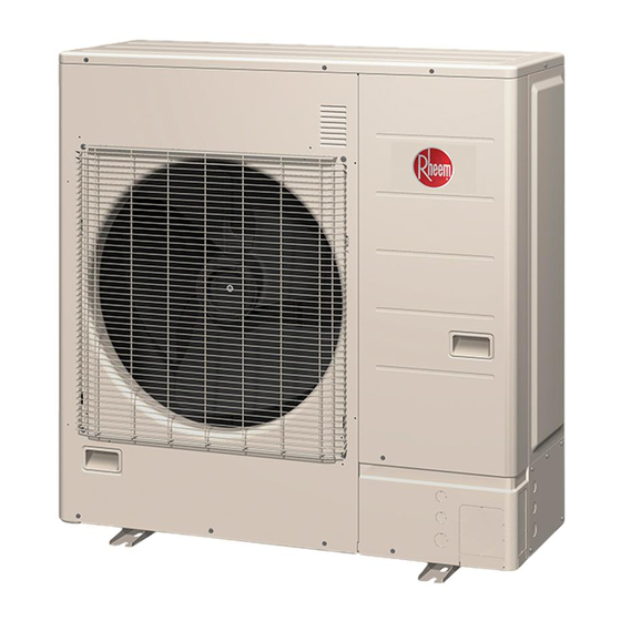
• Variable speed inverter-driven compressor for maximum
comfort and energy savings. Provides heating down to -5ºF
• Outdoor sound levels as low as 53 dBA - quiet operation for
areas with noise constraints
• Space saving single fan outdoor unit
Rheem Classic Plus
Side Discharge Heat Pump
RP17**H Series
Efficiency: 19 SEER/12 EER/10.7 HSPF
Nominal Sizes 2, 2.5, 3 & 4 Ton
[7.03, 8.8, 10.6 & 14.06 kW]
Cooling Capacities 24 to 45.6 kBTU
[7.03 to 13.36 kW]
• High efficiency DC motor
• Communicating heat pump with multi-position air handler
• Compact size - ideal for areas with tight space constraints
Air
®
Series
18.5
Heat Pumps
RP17**H Series
FORM NO. P11-821 REV. 1
Advertisement
Table of Contents

Subscribe to Our Youtube Channel
Related Manuals for Rheem Classic Plus Series


Summary of Contents for Rheem Classic Plus Series
- Page 1 Heat Pumps RP17**H Series Rheem Classic Plus ® Series Side Discharge Heat Pump RP17**H Series Efficiency: 19 SEER/12 EER/10.7 HSPF Nominal Sizes 2, 2.5, 3 & 4 Ton [7.03, 8.8, 10.6 & 14.06 kW] Cooling Capacities 24 to 45.6 kBTU [7.03 to 13.36 kW]...
-
Page 2: Table Of Contents
Table of Contents RP17**H Series TABLE OF CONTENTS Model Number Identification ..................3 Available SKUs ......................3 Physical Data ......................4 Electrical Characteristics ..................5 Accessories ......................6 Sound Pressure ....................7-9 Unit Dimensions ....................10-12 Installation Space ....................13-19 Wiring ........................20-21 Refrigerant Circuit Information ................22-23 Charge Calculation ....................24 Airflow ........................25 Capacity Compensation..................26-27 Safety Devices ......................28... -
Page 3: Model Number Identification
Model Number Identification/Available SKUs RP17**H Series... -
Page 4: Physical Data
Physical Data RP17**H Series Physical Data Type Inverter Heat Pump Model Name RP1724HJVXA RP1730HJVXA RP1736HJVXA RP1748HJVXA Power supply 208/230 V ~ 60 Hz Power supply intake Outdoor unit Available voltage range 187—253 V Starting current 11.5 20.1 Cooling 2,119 (3,600) 2,590 (4,400) Airflow rate CFM (m... -
Page 5: Electrical Characteristics
Electrical Characteristics RP17**H Series Electrical Characteristics Model Name Item Unit RP1724HJVXA RP1730HJVXA RP1736HJVXA RP1748HJVXA Voltage 208/230 V~ Power supply Frequency MCA *1 20.8 39.9 Starting current 11.5 20.1 Max. Ckt. Bkr. *3 Power cable 16—14 Wiring spec.*2 Size 20—16 Connection cable *4 Limited wiring length ft (m) 167 (51) -
Page 6: Accessories
Accessories RP17**H Series Accessories RP1724HJVXA AND RP1730HJVXA RP1736HJVXA AND RP1748HJVXA QUANTITY QUANTITY PART NAME EXTERIOR PART NAME EXTERIOR Installation manual Installation manual Drain pipe Drain pipe Drain cap Drain cap... -
Page 7: Sound Pressure
Sound Pressure RP17**H Series Noise Level Curve MODEL RP1724HJVXA COOLING MODEL RP1724HJVXA HEATING MODEL RP1730HJVXA COOLING MODEL RP1730HJVXA HEATING... - Page 8 Sound Pressure RP17**H Series Noise Level Curve (con’t) MODEL RP1736HJVXA COOLING MODEL RP1736HJVXA HEATING MODEL RP1748HJVXA COOLING MODEL RP1748HJVXA HEATING...
- Page 9 Sound Pressure RP17**H Series Noise Level Check Point NOTE: Detailed shape of the actual outdoor unit might be slightly different from the one illustrated above. [ ] Designates Metric Conversions...
- Page 10 Unit Dimensions RP17**H Series Unit Dimensions—RP1724HJVXA and RP1730HJVXA TOP VIEW [77 mm] [31 mm] [900 mm] [330 mm] [12 mm] [830 mm] [440 mm] [9 mm] [400 mm] [21 mm] FRONT VIEW SIDE VIEW [650 mm] AIRFLOW [99 mm] [370 mm] [196 mm] [147 mm] BOTTOM VIEW...
- Page 11 Unit Dimensions RP17**H Series Unit Dimensions—RP1736HJVXA and RP1748HJVXA [210 mm] [166 mm] [154 mm] [970 mm] [650 mm] [370 mm] [32 mm] TERMINAL BLOCKS [998 mm] 3-WAY VALVE (LIQUID) [36 mm] 3-WAY VALVE (GAS) [530 mm] [95 mm] [297 mm] (GAS VALVE) [32 mm] [370 mm]...
-
Page 12: Unit Dimensions
Unit Dimensions RP17**H Series Unit Dimensions—RP1736HJVXA and RP1748HJVXA (con’t) [315 mm] [140mm] [296 mm] [321 mm] [305 mm] [341 mm] [40 mm] 3 [76 mm] [278 mm] [438 mm] [526 mm] [622 mm] [690 mm] DETAIL A [65 mm] [15 mm] [14 mm] [50 mm] [ ] Designates Metric Conversions... - Page 13 Installation Space RP17**H Series Installation Space—RP1724HJVXA and RP1730HJVXA SPACE REQUIREMENT Provide sufficient installation space for product safety. SINGLE OUTDOOR UNIT INSTALLATION When the upper space is open: WHEN THERE ARE OBSTACLES AT THE REAR ONLY. WHEN THERE ARE OBSTACLES AT THE REAR AND SIDES. 4 [100 mm] OR MORE 12 [300 mm]...
-
Page 14: Installation Space
Installation Space RP17**H Series Installation Space—RP1724HJVXA and RP1730HJVXA (con’t) MULTIPLE OUTDOOR UNIT INSTALLATION When the upper space is open: WHEN THERE ARE OBSTACLES AT THE REAR ONLY. WHEN THERE ARE OBSTACLES AT THE FRONT ONLY. 60 [1500 mm] 10 [250 mm] 12 [300 mm] OR MORE OR MORE... - Page 15 Installation Space RP17**H Series Installation Space—RP1724HJVXA and RP1730HJVXA (con’t) OUTDOOR UNIT INSTALLATION IN MULTI-ROW SINGLE PARALLEL UNIT ARRANGEMENT MULTIPLE PARALLEL UNIT ARRANGEMENT 6 [150 mm] OR MORE 20 [500 mm] OR MORE 79 [2000 mm] OR MORE 24 [600 mm] OR MORE 24 [600 mm] OR MORE 60 [1500 mm] OR MORE 40 [1000 mm] OR MORE...
- Page 16 Installation Space RP17**H Series Installation Space—RP1736HJVXA and RP1748HJVXA CAUTION: 4. The installation space shown in the following examples is based on an ambient temperature under cooling operation of 95ºFDB [35ºCDB] at the air intake of the outdoor unit. Provide more space around the air intake than shown in the examples if the ambient temperature exceeds 95ºFDB [35ºCDB] or if the thermal load of all of the outdoor units exceeds the capacity.
- Page 17 Installation Space RP17**H Series Installation Space—RP1736HJVXA and RP1748HJVXA (con’t) SPACE REQUIREMENT Provide sufficient installation space for product safety. SINGLE OUTDOOR UNIT INSTALLATION When the upper space is open: WHEN THERE ARE OBSTACLES AT THE REAR ONLY. WHEN THERE ARE OBSTACLES AT THE REAR AND SIDES. 8 [200 mm] OR MORE 12 [300 mm]...
- Page 18 Installation Space RP17**H Series Installation Space—RP1736HJVXA and RP1748HJVXA (con’t) MULTIPLE OUTDOOR UNIT INSTALLATION NOTES: 1. Provide at least of space between the outdoor units if multiple units are installed. 2. When routing the piping from the side of an outdoor unit, provide space for the piping. 3.
- Page 19 Installation Space RP17**H Series Installation Space—RP1736HJVXA and RP1748HJVXA (con’t) When there is an obstruction in the upper space: WHEN THERE ARE OBSTACLES AT THE REAR AND ABOVE. 60 [1500 mm] OR MORE 60 [1500 mm] OR MORE 20 [500 mm] OR MORE MAXIMUM 11 [300 mm] OUTDOOR UNIT INSTALLATION IN MULTI-ROW SINGLE PARALLEL UNIT ARRANGEMENT...
-
Page 20: Wiring
Wiring RP17**H Series Wiring—RP1724HJVXA and RP1730HJVXA... - Page 21 Wiring RP17**H Series Wiring—RP1736HJVXA and RP1748HJVXA...
-
Page 22: Refrigerant Circuit Information
Refrigerant Circuit Information RP17**H Series Refrigerant Circuit Information—RP1724HJVXA and RP1730HJVXA HEAT EXCHANGER 3-WAY (INDOOR) VALVE MUFFLER 2-WAY VALVE PRESSURE SWITCH 4-WAY VALVE STRAINER EXPANSION VALVE STRAINER HEAT EXCHANGER PRESSURE (OUTDOOR) CHECK VALVE COOLING HEATING THERMISTOR (COMPRESSOR TEMPERATURE) THERMISTOR (DISCHARGE TEMPERATURE) THERMISTOR (OUTDOOR TEMPERATURE) THERMISTOR (HEAT EXCHANGER OUT TEMPERATURE) THERMISTOR (ROOM TEMPERATURE) - Page 23 Refrigerant Circuit Information RP17**H Series Refrigerant Circuit Information—RP1736HJVXA and RP1748HJVXA OUTDOOR UNIT INDOOR UNIT FUSIBLE PLUG : CHECK VALVE : THERMISTOR (SHELL) : STRAINER : THERMISTOR (DISCHARGE TEMPERTUR THERMISTOR) CMP : COMPRESSOR (INVERTER TYPE) : THERMISTOR (OUTDOOR TEMPERATURE) HEX : HEAT EXCHANGER : THERMISTOR (HEAT EXCHANGER OUT TEMPERATURE) ACM : ACCUMULATOR : THERMISTOR (ROOM TEMPERATURE)
-
Page 24: Charge Calculation
Charge Calculation RP17**H Series Charge Calculation R410A MODEL NUMBERS REFRIGERANT TYPE 4 Lb. 10 Oz. RP1724HJVXA Refrigerant amount RP1730HJVXA 2,100 9 Lb. 8 Oz. RP1736HJVXA Refrigerant amount RP1748HJVXA 4,300 R410A Model No. Refrigerant Type 66 or less 164 (Max.) — Total pipe length 20 or less 50 (Max.) -
Page 25: Airflow
Airflow RP17**H Series Airflow Model No. Cooling Heating 3600 3600 RP1724HJVXA 1000 1000 RP1730HJVXA 2119 2119 4400 4400 RP1736HJVXA 1222 1222 RP1748HJVXA 2590 2590... -
Page 26: Capacity Compensation
Capacity Compensation RP17**H Series Capacity Compensation Rate for Pipe Length and Height Difference HEIGHT DIFFERENCE H INDOOR UNIT IS HIGHER THAN OUTDOOR UNIT* INDOOR UNIT IS LOWER THAN OUTDOOR UNIT* OUTDOOR UNIT INDOOR UNIT OUTDOOR UNIT INDOOR UNIT CONNECTION PIPE CONNECTION PIPE Pipe Length Model No. - Page 27 Capacity Compensation RP17**H Series Capacity Compensation (con’t) Pipe Length Model No. Heating — — — — 0.939 0.922 0.907 — — — — — 0.963 0.939 0.922 0.907 — — Indoor unit is higher than — — 0.999 0.963 0.939 0.922 0.907 —...
-
Page 28: Safety Devices
Safety Devices RP17**H Series Safety Devices Model Type of Protection Protection From RP1724HJVXA RP1730HJVXA Current fuse (filter PCB) 250 V, 5 A x 2 Circuit protection Current fuse (main PCB) 250 V, 3.15 A x 2 + 27 -18 + 15 -10 °F (150 °C) Activate... -
Page 29: Function Settings
Function Settings RP17**H Series Function Settings SETTING METHODS WARNING: Never touch electrical components such as the ter- minal blocks or reactor except the switch on the display board. It may cause a serious accident such as electric shock. CAUTION • Once refrigerant charging is completed, be sure to open the valve prior to performing the location settings. - Page 30 Function Settings RP17**H Series Function Settings (con’t) SETTING METHOD 1. Be sure to disconnect the power supply or tun off the breaker. 2. Change the DIP switch setting according to the required setting. • Various settings can be adjusted by changing DIP switches and push switches on the board of the outdoor unit.
- Page 31 Function Settings RP17**H Series Description of Display Function Or Operation Method LED Display Lamp • Turns on when the power supply is ON (including when error occurs) Power/Mode Green • Indicate the MODE by the number of flashes when the installation function is active. Error Flashes at high-speed when there is an error.
-
Page 32: Test
Test RP17**H Series Test TEST RUN 3. Press “TEST RUN” switch for more than 3 seconds. The POWER/MODE LED flashes once. CAUTION: Always connect the power supply 12 hours prior to the start of the operation in order to protect the compressor. 4. - Page 33 Test RP17**H Series Error Code If an error occurs, the LED will light up to display the error location ERROR CODE DISPLAY and the error code. While the error is occurring, briefly press SW1. The error code is IN THE EVENT OF AN ERROR displayed.
- Page 34 Test RP17**H Series Error Code (con’t) Error Type Error Code 11.3 Serial communication error 11.4 Serial communication error during operation 16.5 Communication error between controller and outdoor unit 22.1 Indoor unit capacity error 5U.1 Indoor unit error 62.1 Outdoor unit PCB Model Information error 62.3 EEPROM access error 62.8...
- Page 35 Test RP17**H Series Pump Down WARNING: During the pump down operation, make sure that 4. Close the liquid pipe valve. compressor is off before you remove the refrigerant piping. Do not 5. When the value between 7.3 psi and 0 psi (0.05 Mpa to 0 Mpa) remove the connection pipe while the compressor is in operation is shown, close the gas pipe valve.
-
Page 36: Limited Warranty
Limited Warranty RP17**H Series GENERAL TERMS OF LIMITED WARRANTY* Rheem will furnish a replacement for any part of this product Parts ............Ten (10) Years which fails in normal use and service within the applicable period stated, in accordance with the terms of the limited warranty. - Page 37 Notes RP17**H Series...
- Page 38 Notes RP17**H Series...
- Page 39 Notes RP17**H Series...
- Page 40 ™ The new degree of comfort. In keeping with its policy of continuous progress and product improvement, Rheem reserves the right to make changes without notice. Rheem Heating, Cooling & Water Heating • 5600 Old Greenwood Road Rheem Canada Ltd./Ltée • 125 Edgeware Road, Unit 1 Fort Smith, Arkansas 72908 •...
Need help?
Do you have a question about the Classic Plus Series and is the answer not in the manual?
Questions and answers