
Related Manuals for Videotec DTRXDC


Summary of Contents for Videotec DTRXDC
- Page 1 MANUALE D’USO __________________________ OPERATING INSTRUCTIONS __________________________ MANUEL D’INSTRUCTIONS __________________________ BEDIENUNGSANWEISUNG...
- Page 2 MANUALE D’USO...
-
Page 3: Table Of Contents
Convenzioni tipografiche ................................... 2 NORME DI SICUREZZA.................................2 DATI DI MARCATURA ................................3 DESCRIZIONE DEL RICEVITORE DTRXDC.........................3 Caratteristiche ......................................3 Apparecchi compatibili per l’uso con il ricevitore DTRXDC ........................3 Esempio di installazione .................................... 4 Cavi..........................................4 INSTALLAZIONE ..................................5 Apertura dell’imballaggio ................................... 5 Controllo della marcatura .................................. -
Page 4: Introduzione
Controllare che il contenuto sia rispondente alla lista del materiale sopra indicata. Cosa contiene questo manuale In questo manuale è descritto il ricevitore DTRXDC, con le particolari procedure di installazione, configurazione e utilizzo. E’ necessario leggere attentamente questo manuale, in particolar modo il capitolo concernente le norme di sicurezza, prima di installare ed utilizzare il ricevitore. -
Page 5: Dati Di Marcatura
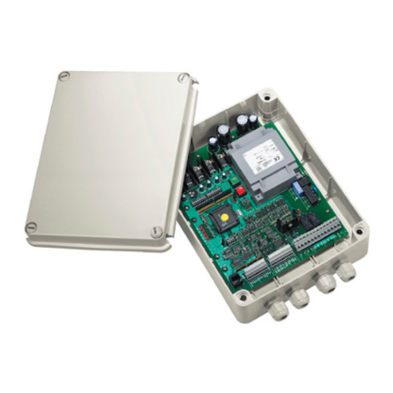
L’uso di apparecchi non idonei può portare a gravi pericoli per la sicurezza del personale e dell’impianto. Descrizione del ricevitore DTRXDC Il ricevitore DTRXDC è un ricevitore di comandi a microprocessore per il controllo remoto del brandeggio PTH355P, ottiche motorizzate e funzioni ausiliarie. -
Page 6: Esempio Di Installazione
• 2 monitor • 3 telecamere (+ 1 nel ricevitore OEM) • 1 matrice video SW328 SW328 Gestione della telemetria: • 3 ricevitori DTRXDC • 3 brandeggi PTH355P • 1 ricevitore OEM (con camera incorporata) DCS3 Cavi Negli schemi d’esempio sono stati utilizzati diversi tipi di tratto per indicare cavi di diversa funzione: cavo telefonico: 1,5 m, fornito in dotazione con la tastiera. -
Page 7: Installazione
− 0,75 mm.² (AWG 18) CENELEC H05VV-F per fili di alimentazione DTRXDC Il cavo multipolare del preset non deve essere in comune ad altre funzioni. cavo per la ricezione/trasmissione digitale dei comandi: 2 fili per la ricezione dall’unità di comando (doppino telefonico twistato, sezione 0,22 mm.² AWG 24) 2 fili per la eventuale trasmissione al ricevitore successivo nelle configurazione in cascata (doppino telefonico twistato, sezione 0,22 mm.²... -
Page 8: Collegamento Alla Rete Di Alimentazione
• Tipo di ottiche controllate • Impostazione della velocità di comunicazione • Impostazione degli ausiliari AUX1 / AUX2 • Collegamento con l’unità di comando • Regolazione della tensione di controllo dell’ottica • Collegamento dei cavi del brandeggio e delle ottiche Pag. 6 DTRXDC 0500... -
Page 9: Impostazione Del Numero Di Identificazione Del Ricevitore
--++ +--- +-++ ++-- -+++ +-+- +-++ +--- -+++ ++-- ++++ +-+- -+++ +--- ++++ ++-- ---- -++- ++++ +--- ---- --+- +--- -++- ---- -+-- +--- --+- -+-- -++- +--- -+-- -+-- --+- ++-- -++- Pag. 7 DTRXDC 0500... -
Page 10: Modalità Di Comunicazione Del Dtrxdc
ATTENZIONE : Il collegamento errato delle ottiche può causare il danneggiamento delle ottiche! Il DTRXDC è in grado di controllare sia ottiche a inversione di polarità, sia a filo comune. In caso di ottiche a filo comune collegare il filo comune a FOCUS-. -
Page 11: Collegamento Con L'unità Di Comando
Collegamento con l’unità di comando La tastiera DCS3 e il ricevitore DTRXDC possono essere collegati direttamente tramite il cavo telefonico fornito dal fabbricante utilizzando il connettore RJ11 presente nel circuito, secondo la tabella di riferimento riportata di seguito. Collegamento DCS3- ricevitore DTRXDC Modalità... -
Page 12: Più Ricevitori Per Linea, Collegamento Con Doppino Twistato
- effettuare i collegamenti con ottica, brandeggio e cavi degli allarmi - dare alimentazione all’unità La lunghezza del cavo di collegamento tra il connettore J3 del ricevitore DTRXDC ed il brandeggio non deve superare i 5 metri . Pag. 10... -
Page 13: Uso Dei Contatti Di Allarme
è attivato il brandeggio e l’ottica si portano nella posizione di preset corrispondente; l’ultimo allarme arrivato ha sempre la priorità più alta. E’ possibile che il DTRXDC riceva un comando di allarme anche attraverso la tastiera di comando DTRXDC (che lo riceve a sua volta dalla matrice SW328), in tal caso brandeggio ed ottica si portano nella posizione di preset n.1. -
Page 14: Accensione E Spegnimento
Descrizione della marcatura . • controllare che il fusibile F1 di protezione del ricevitore DTRXDC sia integro • controllare che il ricevitore e gli altri componenti dell’impianto siano chiusi e sia quindi impossibile il contatto diretto con parti in tensione. -
Page 15: Risoluzione Di Problemi
Risoluzione di problemi Il ricevitore DTRXDC è caratterizzato da una notevole facilità d’uso, ma ciononostante possono insorgere dei problemi sia in fase di installazione, di configurazione o durante l’uso. • Manca alimentazione • Controllare il cavo di alimentazione Il led LD8 è spento •... - Page 16 OPERATING INSTRUCTIONS...
- Page 17 SAFETY RULES ..................................2 OPERATING DATA ON THE RATING PLATE ........................3 DESCRIPTION OF THE DTRXDC RECEIVER ........................3 Features ........................................3 Compatible devices for the use with the DTRXDC receiver ........................3 Installation examples ....................................4 Cables ........................................4 INSTALLATION ..................................5 Unpacking........................................5 Control of the operating data on the rating plate ............................
- Page 18 Safety rules The DTRXDC receiver complies with the rules in force at the time of publication of the present manual as regards the electric safety, the electromagnetic compatibility and the other general requirements.
- Page 19 The use of unsuitable devices can lead to serious risks for the safety of the personnel and the security of the plant. Description of the DTRXDC receiver The DTRXDC receiver is a microprocessor-based command receiver for the remote control of Pan & Tilt, motorized lenses and auxiliary functions. Features •...
- Page 20 • 2 monitor • 3 cameras (+ 1 in the receiver OEM) • 1 SW328 video matrix SW328 Telemetry section: • 3 DTRXDC receivers • 3 PTH355P Pan & Tilt • 1 receiver OEM (with camera included) DCS3 Cables In the diagrams given as examples, different types of lines have been used to show cables with different functions: telephone cable: 1.5 m, supplied with the keyboard.
- Page 21 − 0,75 mm.² (AWG 18) CENELEC H05VV-F for DTRXDC power supply wires. The multipolar cable of the preset must not be in common with other functions. cable for digital reception/transmission of commands: 2 wires for reception from control unit (twisted telephone pair, section 0.22 mm² AWG 24) 2 wires for possible transmission to the next receiver in cascade configuration (twisted telephone pair, section 0.22...
- Page 22 • Type of lenses used • Communication speed • AUX1 / AUX2 auxiliary devices • Connection with the control unit • Control voltage of lenses • Connection of the cables of the Pan & Tilt and the lenses Pag. 6 DTRXDC 0500...
- Page 23 --++ +--- +-++ ++-- -+++ +-+- +-++ +--- -+++ ++-- ++++ +-+- -+++ +--- ++++ ++-- ---- -++- ++++ +--- ---- --+- +--- -++- ---- -+-- +--- --+- -+-- -++- +--- -+-- -+-- --+- ++-- -++- Pag. 7 DTRXDC 0500...
- Page 24 The DTRXDC receiver can control both polarity inversion lenses and common wire lenses. In case of common wire lenses, connect the common wire to FOCUS -. Communication speed The DTRXDC receiver can communicate with a speed of 1200 or 9600 baud, so it can be used in digital transmittion systems. Dip switch : switch 8 of SW1...
- Page 25 Connection to the control unit The DCS3 keyboard and the receiver DTRXDC can be connected directly using the telephone cable supplied by the manufacturer and using the RJ11 connector present on the circuit, following the table of reference given below.
- Page 26 2. connect the unit with the lens, Pan & Tilt and alarms 3. power the unit The length of the connecting cable between connector J3 of the DTRXDC receiver and the tilt & pan should not exceed 5 metres. Pag. 10...
- Page 27 Use of the alarm contacts The DTRXDC receiver is fitted with 4 alarm contacts; they are associated with the first four preset positions; as soon as the alarm is activated, the positioning device and the lens adopt the corresponding preset position; the last alarm activated takes always priority.
- Page 28 Operating data on the rating plate . • make sure that the fuse F1 of the DTRXDC receiver are not damaged. • make sure that the receiver and the other components of the plant are closed in order to avoid the direct contact with live elements.
- Page 29 Troubleshooting Although the DTRXDC receiver is characterized by a great ease of use, sometimes troubles may occur, especially during the installation and configuration phases or using the unit.. • No power supplied to the unit • Check the power cord Led LD8 is off •...
- Page 30 MANUEL D’INSTRUCTIONS...
- Page 31 Conventions typographiques ..................................2 NORMES DE SÉCURITÉ ...............................2 CARACTÉRISTIQUE TECHNIQUES .............................3 DESCRIPTION DU RÉCEPTEUR DTRXDC ..........................3 Caractéristiques......................................3 Appareils compatibles pour l’emploi avec le récepteur DTRXDC......................3 Exemples d’installations .................................... 4 Câbles ........................................4 INSTALLATION ..................................5 Déballage ........................................5 Contrôle des caractéristiques techniques..............................5 Dip-Switch et pontets de configuration ..............................
- Page 32 Description des caractéristiques du système: lire attentivement pour comprendre les phases suivantes. Normes de sécurité Le récepteur DTRXDC est conforme aux normes en vigueur au moment de la publication de ce manuel pour ce qui concerne la sécurité électrique, la compatibilité électromagnétique et les conditions requises générales.
- Page 33 L’emploi d’appareils non appropriés peut compromettre sérieusement la sécurité du personnel et de l’installation. Description du récepteur DTRXDC Le DTRXDC est un récepteur de commandes à microprocesseur pour le contrôle à distance de la tourelle PTH355P, des objectifs motorisés et des fonctions auxiliaires. Caractéristiques •...
- Page 34 A noter: il est conseillé d’utiliser différents câbles multipolaires pour les diverses fonctions. Section minimale conseillée: − 0,56 mm.² (AWG 20) pour raccordements en haute tension. − 0,34 mm.² (AWG 22) pour raccordements en basse tension. − 0,75 mm.² (AWG 18) CENELEC H05VV-F pour fils d’alimentation DTRXDC Pag. 4 DTRXDC 0500...
- Page 35 Ne jamais effectuer des modifications ou des branchements non prévus dans ce manuel: l’emploi d’appareils non appropriés peut compromettre sérieusement la sécurité des personnes et de l’installation. Dip-Switch et pontets de configuration Dans le schéma suivant identifier les Dip-switch et les pontets de configuration: Pag. 5 DTRXDC 0500...
- Page 36 • Réglage de la vitesse de transmission • Position des fonctions auxiliaires AUX1 / AUX2 • Liaison avec l’unité de commande • Réglage de la tension de contrôle de l’objectif • Raccordement des câbles tourelle et objectifs. Pag. 6 DTRXDC 0500...
- Page 37 --++ +--- +-++ ++-- -+++ +-+- +-++ +--- -+++ ++-- ++++ +-+- -+++ +--- ++++ ++-- ---- -++- ++++ +--- ---- --+- +--- -++- ---- -+-- +--- --+- -+-- -++- +--- -+-- -+-- --+- ++-- -++- Pag. 7 DTRXDC 0500...
- Page 38 ATTENTION: La connexion incorrecte du type d’objectifs peut être cause d’endommagement des optiques! Le DTRXDC est à même de contrôler soit des objectifs à inversion de polarité, soit à fil commun. Dans le cas d’objectif à fil commun, raccorder le commun sur la borne FOCUS-.
- Page 39 Raccordement de plusieurs récepteurs en cascade DCS3 Les récepteurs DTRXDC peuvent régénérer en eux le signal reçu et le renvoyer sur une nouvelle ligne de communi- cation vers le récepteur successif. Chacune des trois sections de ligne (L1, L2, L3) est considérée indépendante et relie, point à...
- Page 40 Effectuer les raccordements à l’objectif, à la tourelle et aux câbles d’alarme • Mettre l’unité sous tension La longueur du câble de raccordement entre le connecteur J3 du récepteur DTRXDC et la tourelle ne doit pas dépasser 5 mètres . Pag. 10...
- Page 41 à la préposition. Le DTRXDC peut recevoir un commande d’alarme aussi par le pupitre de commande DCS3 (qui, à son tour, le reçoit del a matrice SW328), dans ce cas tourelle et objectif se placent à la position de préposition n.1.
- Page 42 • vérifier si le matériel fourni, figurant sur les plaques, correspond aux spécifications requises, suivant la description au chapitre Caractéristiques techniques . • vérifier si le fusible de protection F1 du récepteur DTRXDC soit intacts • contrôler si le récepteur et les composantes de l’installation sont fermés , afin d’éviter le contact direct avec parties sous tension.
- Page 43 Résolution de problèmes Bien que le récepteur DTRXDC se caractérise par une excellente facilité d’emploi, des problèmes peuvent se produire en phase d’installation, de configuration ou pendant l’emploi. • Alimentation non raccordée • Contrôler le câble d’alimentation Il led LD8 reste éteint •...
- Page 44 BEDIENUNGSANWEISUNG...
-
Page 45: Inhaltsverzeichnis
EINFÜHRUNG..................................2 Verpackungsinhalt ..................................... 2 Inhalt des vorliegenden Bedienungshandbuchs............................2 Typographische Symbole ..................................2 UNFALLVERHÜTUNGSVORSCHRIFTEN ..........................2 BETRIEBSEIGENSCHAFTEN AUF DEN DATENSCHILDERN ....................3 BESCHREIBUNG DES EMPFÄNGERS DTRXDC ........................3 Eigenschaften......................................3 DTRXDC-kompatible Geräte ..................................3 Aufstellungsbeispiele....................................4 Kabel ......................................... 4 AUFSTELLUNG..................................5 Auspacken des Gerätes .................................... 5 Kontrolle der Betriebseigenschaften auf den Datenschildern........................ -
Page 46: Einführung
Phasen zu verstehen. Unfallverhütungsvorschriften Der Empfänger DTRXDC entspricht den Rechtsvorschriften in Kraft zur Zeit der Veröffentlichung des vorliegenden Bedienungshandbuchs in bezug auf die elektrische Sicherung, die elektromagnetische Kompatibilität und die anderen allgemeinen Forderungen. Beachten Sie die folgenden Vorsorgemaßnahmen, um die Sicherheit der Benutzer (Installateur und Operator) zu gewährleisten:... -
Page 47: Betriebseigenschaften Auf Den Datenschildern
Stromversorgungseigenschaften den Forderungen entsprechen. Die Anwendung unzweckmäßiger Geräte kann die Sicherheit des Personals und der Anlage gefährden. Beschreibung des Empfängers DTRXDC Der Empfänger DTRXDC ist ein Befehlsempfänger auf Mikroprozessorbasis für die Fernsteuerung von Schwenkvorrichtungen, motorisierten Linsen, Wischer, Scheibenwascherpumpe und Hilfsfunktionen. Eigenschaften •... -
Page 48: Aufstellungsbeispiele
− 0,56 mm.² (AWG 20) für Anschlußen in Hochspannung. − 0,34 mm.² (AWG 22) für Anschlußen in Niederspannung. − 0,75 mm.² (AWG 18) CENELEC H05VV – F für DTRXDC-Speisungsdrähte Das mehrpolige Kabel für die Voreinstellung darf nicht einen gemeinsamen Betrieb mit anderen Funktionen haben. -
Page 49: Aufstellung
Keine in diesem Bedienungshandbuch nicht vorgesehenen Veränderungen oder Anschlüsse ausführen: die Anwendung von ungeeigneten Geräten kann die Sicherheit des Personals und der Anlage gefährden. Dip-switch und Jumpers In der folgenden Zeichnung identifizieren Sie die Dip-switch und Jumpers des Empfängers: Pag. 5 DTRXDC 0500... -
Page 50: Anschluß An Dem Speisungsnetz
• Steuerung der Art von Linsen • Setzen der Übertragungsgeschwindigkeit • Setzen der Zusatzgeräte AUX 1 / AUX2 • Verbindung mit der Steuerungseinheit • Einstellung der Steuerspannung der Linse • Anschluß der Kabel der Schwenkvorrichtung und der Linsen Pag. 6 DTRXDC 0500... -
Page 51: Setzen Der Identifikationsnummer Des Empfängers
--++ +--- +-++ ++-- -+++ +-+- +-++ +--- -+++ ++-- ++++ +-+- -+++ +--- ++++ ++-- ---- -++- ++++ +--- ---- --+- +--- -++- ---- -+-- +--- --+- -+-- -++- +--- -+-- -+-- --+- ++-- -++- Pag. 7 DTRXDC 0500... -
Page 52: Übertraggungsmodus Des Dtrxdc
Steuerung der Art von Linsen ACHTUNG!: Eine unrichtige Verbindung Parameter kann die Linsen beschädigen. Die DTRXDC-Einheit kann die beiden Umpolungslinsen und die Linsen mit gemeinsamen Draht kontrollieren. Bei Linsen mit gemeinsamem Draht, den gemeinsamen Draht an FOCUS- anschließen. Setzen der Übertragungsgeschwindigkeit Geeignet auch für die Nutzung der Übertragungsdigitalsysteme, die Übertragungsgeschwindigkeit der Einheit hat von... -
Page 53: Verbindung Mit Der Steuereinheit
Verbindung mit der Steuereinheit Die DCS3-Tastatur und der DTRXDC-Empfänger können direkt durch ein vom Hersteller mitgeliefertes Telefonkabel verbunden werden. Hierzu gemäß der nachstehenden Richttabelle den Steckverbinder RJ11 verwenden, der Bestandteil des Schaltkreises ist. Verbindung DCS3-Tastatur - DTRXDC-Empfänger Kommunikationsmodalitäten RS485: Höchstentfernung... -
Page 54: Mehrere Empfänger Pro Leitung, Verbindung Mit Verdrilltem Aderpaar
Tastatur bis zum Empfänger A3) beträgt 1200 Meter. Einstellung der Steuerspannung der Linse - das Stromkabel anschließen und die DTRXDC-Einheit einschalten ( LD8 leuchtet ) - die Auflagestifter des Prüfgeräts auf die Klemmen FOCUS+ und FOCUS- positionieren - eine der zwei FOCUS-Tasten der DCS3-Steuerungseinheit gedrückt halten Ù... -
Page 55: Anwendung Der Alarmkontakte
Alarm aktiviert, nehmen die Schwenkvorrichtung und die Linse die dazugehörige PRESET-Position ein; der zuletzt aktivierte Alarm hat für immer Vorrang. Der DTRXDC kann auch einen Alarmbefehl durch die Steuerungstastatur DCS3 empfangen, die ihn ihrerseits von der Matrix SW328 enthält; in diesem Fall nehmen die Schwenkvorrichtung und der Linse die PRESET-Position Nr. -
Page 56: Einschalten Und Ausschalten
Datenschilder gemäß der Beschreibung in Kapitel Betriebseigenschaften auf den Datenschildern . • stellen Sie sicher, daß die F1-Abschmelzsicherung des DTRXDC-Empfängers keinen Defekt aufweist. • vergewissern Sie sich, daß der Empfänger und die anderen Komponenten der Anlage geschlossen sind, um den direkten Kontakt mit stromführenden Elementen zu vermeiden. -
Page 57: Fehlersuche
Fehlersuche Obwohl der DTRXDC-Empfänger durch eine hohe Zuverlässigkeit und gute Bedienbarkeit charakterisiert ist, können manchmal Schwierigkeiten beim Installieren und Konfigurieren des System oder während Ihrer Arbeit auftreten • Stromausfall • Netzkabel prüfen LED-Anzeige LD8 ist • Durchgebrannte Sicherung • Sicherung F1 ersetzen ausgeschaltet •...
Need help?
Do you have a question about the DTRXDC and is the answer not in the manual?
Questions and answers