
Related Manuals for Videotec MICRODEC485


Summary of Contents for Videotec MICRODEC485
- Page 1 MANUALE D’USO __________________________ OPERATING INSTRUCTIONS __________________________ MANUEL D’INSTRUCTIONS __________________________ BEDIENUNGSANWEISUNG...
- Page 2 MANUALE D’USO...
-
Page 3: Table Of Contents
NORME DI SICUREZZA.................................2 DATI DI MARCATURA ................................3 DESCRIZIONE DEL RICEVITORE MICRODEC485 ......................3 Caratteristiche ......................................3 Apparecchi compatibili per l’uso con il ricevitore MICRODEC485......................3 INSTALLAZIONE ..................................3 Apertura dell’imballaggio ................................... 3 Controllo della marcatura ..................................4 Dip-switch di configurazione ..................................4 Impostazione del numero di identificazione del ricevitore .............. -
Page 4: Introduzione
Controllare che il contenuto sia rispondente alla lista del materiale sopra indicata. Cosa contiene questo manuale In questo manuale è descritto il ricevitore MICRODEC485, con le particolari procedure di installazione, configurazione e utilizzo. E’ necessario leggere attentamente questo manuale, in particolar modo il capitolo concernente le norme di sicurezza, prima di installare ed utilizzare il ricevitore. -
Page 5: Dati Di Marcatura
L’uso di apparecchi non idonei può portare a gravi pericoli per la sicurezza del personale e dell’impianto. Descrizione del ricevitore MICRODEC485 Il ricevitore MICRODEC485 è un ricevitore di comandi a microprocessore per il controllo remoto di brandeggi in 24V~ e ottiche motorizzate ad inversione di polarità. -
Page 6: Controllo Della Marcatura
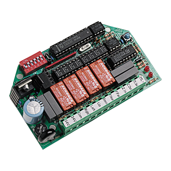
-+++- -++++ ++++- +++++ ----+ ----- Impostazione della velocità di comunicazione - assicurarsi che non sia presente l’alimentazione - configurare il dip switch SW1 secondo lo schema seguente: dip swich 6: OFF 9600 baud 1200 baud Pag. 4 MICRODEC485 9951... -
Page 7: Inserimento Resistenza Di Terminazione Per Seriale Rs485
RS485 il jumper JP1 deve essere in posizione B (resistenza di terminazione non inserita). FASI PER IL MONTAGGIO DEL MICRODEC485 FIG. 1 (1) fondo della custodia... -
Page 8: Collegamento Dei Cavi Del Brandeggio, Delle Ottiche Del Canale Di Comunicazione E Dell'alimentazione
2 fili per la ricezione dall’unità di comando (doppino telefonico twistato, sezione 0,22 mm.² AWG 24) non schermato Nota: la distanza massima del collegamento é di 1200 m in RS485. Pag. 6 MICRODEC485 9951... -
Page 9: Esempio Di Installazione
1 Matrice video SW328 2 monitor MICRODEC485 MICRODEC485 MICRODEC485 MICRODEC485 4 telecamere Parte telemetria: 4 ricevitori MICRODEC485 4 brandeggi SW328 DCS3 Due operatori con un monitor ciascuno, con controllo di un gruppo di ricevitori. MATERIALE Parte di controllo: 2 tastiere di controllo DCS3... -
Page 10: Accensione
• controllare che le fonti di alimentazione ed i cavi di collegamento siano in grado di sopportare il consumo del sistema • verificare di aver fornito alimentazione corretta al MICRODEC485 (24V~) e agli altri componenti installati. Manutenzione Il ricevitore MICRODEC485 non necessita di particolare manutenzione. - Page 11 OPERATING INSTRUCTIONS...
- Page 12 Contents of the packaging..................................2 Contents of this manual..................................... 2 Typographical conventions ..................................2 SAFETY RULES ..................................2 OPERATING DATA ON THE RATING PLATE ........................3 DESCRIPTION OF THE MICRODEC485 RECEIVER ......................3 Features ........................................3 Compatible devices ....................................3 INSTALLATION ..................................3 Unpacking........................................3 Control of the operating data on the rating plate ............................
-
Page 13: Introduction
Safety rules The MICRODEC485 receiver complies with the rules in force at the time of publication of the present manual as regards the electric safety, the electromagnetic compatibility and the other general requirements. -
Page 14: Operating Data On The Rating Plate
The use of unsuitable devices can lead to serious risks for the safety of the personnel and the security of the plant. Description of the MICRODEC485 receiver MICRODEC485 is a microprocessor controlled receiver for the remote control of 24V~ Pan & Tilt motors and of motor zoom lenses of polarity inversion. Features •... -
Page 15: Control Of The Operating Data On The Rating Plate
+++++ ----+ ----- Setting the communication speed - make sure you have cut off the power supply - configure the dip-switch SW1 according to the following table: dip swich 6: OFF 9600 baud ON 1200 baud Page 4 MICRODEC485 9951... -
Page 16: Microdec485 Installation Stages
(4) MICRODEC485 (5) fastening spacers INSTALLATION Fasten the support plate (2) to the housing bottom (1) by the fastening screws (3). Push the MICRODEC485 (4) on the FIG. 2 fastening spacers (5), fixing it to the plate (FIG.2). Page 5... -
Page 17: Connection Of The Pan & Tilt Motor Cables, Of The Communication Channel Zoom Lenses And Of The Power Supply
0.34 mm.² (AWG 22) for low tension wires (zoom, lens, auxiliary) cable for control digital reception/transmission: 2 wires for the control unit reception (twisted pair cable, section 0,22 mm² AWG 24) shieldless Note: the maximum connection distance is about 1200 in Rs485. Page 6 MICRODEC485 9951... -
Page 18: Installation Examples
MICRODEC485 MICRODEC485 MICRODEC485 MICRODEC485 2 monitors 4 cameras Telemetry section: 4 MICRODEC485 receivers 4 Pan & Tilt’s SW328 DCS3 Two operators with a monitor for each one; with control of a set of receivers. DEVICES Control section: 2 DCS3 control keyboards... -
Page 19: Switching On And Switching Off
Led di diagnostica MICRODEC485 Two leds (LL1 and LL2) allow checking the correct running of the MICRODEC485. On switching on, both will rapidly blink for about 1 second. During normal function, LL2 blinks whit a period of 1 second. LL1 blinks shortly when a command is received. - Page 20 MANUEL D’INSTRUCTIONS...
- Page 21 Conventions typographiques ..................................2 NORMES DE SÉCURITÉ ...............................2 CARACTÉRISTIQUES TECHNIQUES ...........................3 DESCRIPTION DU RÉCEPTEUR MICRODEC485........................3 Caractéristiques......................................3 Appareils compatibles pour emploi avec le récepteur MICRODEC485..................... 3 INSTALLATION ..................................3 Déballage ........................................3 Contrôle des caractéristiques techniques..............................4 Dip-switch de configuration..................................4 Intro duction du numéro d’identification du récepteur..........................
- Page 22 Description des caractéristiques du système: lire attentivement pour comprendre les phases suivantes. Normes de sécurité Le récepteur MICRODEC485 est conforme aux normes en vigueur au moment de la publication de ce manuel pour ce qui concerne la sécurité électrique, la compatibilité électromagnétique et les conditions requises générales.
- Page 23 L’emploi d’appareils non appropriés peut compromettre sérieusement la sécurité du personnel et de l’installation. Description du récepteur MICRODEC485 Le MICRODEC485 est un récepteur de commandes à microprocesseur pour le contrôle à distance de tourelles 24V~ et objectifs motorisés à inversion de polarité. Caractéristiques •...
- Page 24 -++++ -+++- ++++- +++++ ----+ ----- Introduction de la vitesse de communication - s’assurer qu’on ait coupé l’alimentation - configurer le dip-switch SW1 selon le schéma suivant: dip swich 6: OFF 9600 baud ON 1200 baud Pag. 4 MICRODEC485 9951...
- Page 25 (5) entretoises de fixation INSTALLATION Fixer la plaque de support (2) au fond du caisson (1) par les vis (3). Monter le FIG. 2 MICRODEC485 (4) à la plaque par les entretoises (5), en exercant une légère pression (FIG.2). Pag. 5 MICRODEC485 9951...
- Page 26 2 fils pour la réception de l’unité de commande (boucle téléphonique, section 0,22 mm.² AWG 24) non blindé Note: la distance max de raccordementest de 1200 m environ en RS485. Pag. 6 MICRODEC485 9951...
- Page 27 2 moniteurs MICRODEC485 MICRODEC485 MICRODEC485 MICRODEC485 4 télécaméras Partie télémetrique: SW328 4 récepteurs MICRODEC485 4 tourelles DCS3 Deux opérateurs avec un moniteur chacun, avec contrôle d’un groupe de récepteurs MATERIEL Partie de commande 2 pupitres DCS3 Partie vidéo: 1 matrice SW328...
- Page 28 Leds de diagnostic du MICRODEC485 Deux leds (LL e LL2) permettent de vérifier le correct fonctionnment du MICRODEC485. A l’allumage tous les deux clignotent rapidement pour 1 seconde environ. Pendant le normal fonctionnement LL2 clignote pour 1 seconde. LL1 clignote brièvement à...
- Page 29 BEDIENUNGSANWEISUNG...
- Page 30 Videotec s.r.l. übernimmt keine Verantwortung für eventuelle Schäden, die auf einen unsachgemäßen Gebrauch der in diesem Handbuch erwähnten Einrichtungen zurückzuführen sind. Videotec s.r.l. behält sich das Recht vor, den Inhalt dieses Handbuchs ohne Vorankündigung zu verändern. Große Sorgfalt wurde auf die Sammlung und Prüfung der in diesem Handbuch enthaltenen Unterlagen verwendet. Jedoch übernimmt Videotec s.r.l.
-
Page 31: Einführung
Phasen zu verstehen. Unfallverhütungsvorschriften Der Empfänger MICRODEC485 entspricht den Rechtsvorschriften in Kraft zur Zeit der Veröffentlichung des vorliegenden Bedienungshandbuchs in bezug auf die elektrische Sicherung, die elektromagnetische Kompatibilität und die anderen allgemeinen Forderungen. Beachten Sie die folgenden Vorsorgemaßnahmen, um die Sicherheit der Benutzer (Installateur und Operator) zu gewährleisten:... -
Page 32: Betriebseigenschaften Auf Den Datenschildern
Betriebseigenschaften auf den Datenschildern Der Empfänger MICRODEC485 ist mit zwei Schildern gemäß der EG-Markierung versehen. Das erste Schild enthält: • Identifikationscode des Modells (erweiterter 3/9 Barcode) • Stromversorgung (Volt) • Frequenz (Hertz) • Verbrauch (Watt) Das zweite Schild gibt die Seriennummer des Modells an (erweiterter 3/9 Barcode). -
Page 33: Kontrolle Der Betriebseigenschaften Auf Den Datenschildern
+-++- +-+++ -+++- -++++ ++++- +++++ ----+ ----- Einstellung der Kommunikationsgeschwindigkeit - Feststellung, daß keine Speisung vorhanden ist - Konfiguration des Dip-Switch SW1 nach dem folgenden Tafel: dip swich 6: OFF 9600 baud ON 1200 baud Seite 4 MICRODEC485 9951... -
Page 34: Schaltung Des Endewiderstandes Für Rs485
(Endewiderstand nicht eingeschaltet) MONTAGESCHRITTE F ÜR MICRODEC485 BILD 1 (1) GehhUSEGRUND (2) St}TZPLATTE (3) Befestigungsschrauben (4) MICRODEC485 (5) Befestigungsabstand INSTALLATION BILD 2 Die St}TZPLATTEýöìõýISTýANýDEMýGehhUSEGRUND öíõý DURCHýDIEý4CHRAUBENýöëõýZUýBEFASTIGENð 6NTERýLEICHTEMý%RUCKýMICRODEC485 (4) in der Platte durch die Distanzst}CKEN EINF}HREN (BILD. 2). Seite 5 MICRODEC485 9951... -
Page 35: Anschluß Der Schwenkungskabel
0,34 mm.² (AWG 22) für Niederspannungsdrähte (Linse, Zusatzgerät) Kabel für das digitale Empfangen/Übertragen von Befehlen: 2 Drähte zum Empfang von der nicht abgeschirmten Steuerungseinheit (twistierte Telephon-Doppelschnur, Querschnitt 0,22 mm.² AWG 24) Anmerkung: Der höchste Anschlußabstand beträgt ungefähr 1200m in RS485. Seite 6 MICRODEC485 9951... -
Page 36: Aufstellungsbeispiele
1 Video-Matrix SW328 MICRODEC485 MICRODEC485 MICRODEC485 MICRODEC485 2 Monitore 4 Kameras Fernmessungssektion: SW328 4 Empfänger MICRODEC485 4 Schwenkvorrichtungen DCS3 Zwei Operatoren: jeder hat einen Monitor, mit Steuerung eines Satz Empfänger. GERÄTE Steuerungssektion: 2 Bedienungstastaturen DCS3 Videosektion: 1 Video-Matrix SW328 2 Monitore... -
Page 37: Einschalten Und Ausschalten
Schwenkvorrichtung nicht behindern. Diagnostik-Led MICRODEC Zwei Led (LL1 und LL2) ermöglichen, den richtigen Betrieb von MICRODEC485 zu prüfen. Am Start blinken alle zwei Led schnell für die Dauer einer Sekunde. Während des normalen Betriebs blinkt LL2 für die Dauer einer Sekunde, dagegen blinkt LL1 kurz Ampfang eines Befehls.
Need help?
Do you have a question about the MICRODEC485 and is the answer not in the manual?
Questions and answers