EGO STA1500 Repair Manual Line
String trimmer attachment
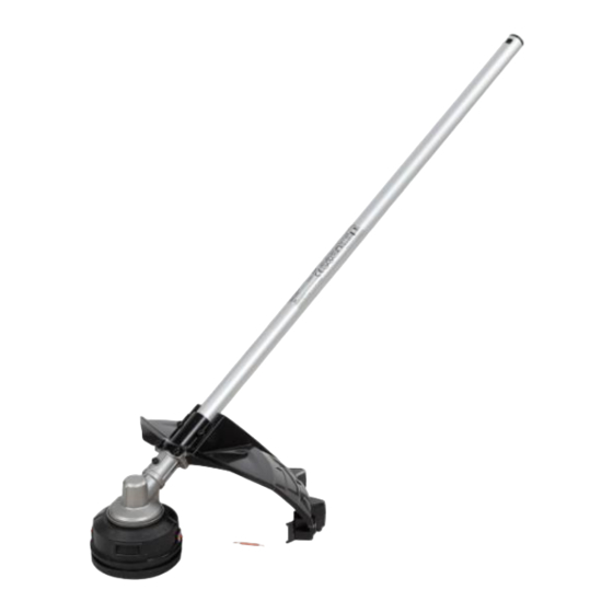
Hide thumbs
Also See for STA1500:
- User manual ,
- Operator's manual (233 pages) ,
- Repair manual line (19 pages)
Advertisement
Quick Links
Advertisement

Related Manuals for EGO STA1500


Summary of Contents for EGO STA1500
- Page 1 REPAIR GUIDELINE String Trimmer Attachment_STA1500 Version: 1 Issue Date: 12/02/2016...
- Page 2 Table of Contents Contents Page Troubleshooting Tool list Part 1: Replace the Housing Assembly and Gear Case 5-29...
- Page 3 Troubleshooting Problem Possible Cause Fault Position Test & Solution Replace the cutting line. (e.g. 2.4mm nylon Not feeding line Poor cutting line Trimmer line line) Support of the lower Lower housing Hard to wind up line Replace the lower housing assembly housing assembly is worn assembly Blade on the guard assembly...
- Page 4 Tool List For Repair Tool List SPEC Remark Socket wrench 14mm Hex wrench...
- Page 5 Part 1: Replace the Housing Assembly and Gear Case...
- Page 6 Replace the Housing Assembly and Gear Case 1. Loosen 2 screws to disassemble the guard assembly, if the guard assembly is broken, replace it with a new one. Guard assembly Description Part Number Qty. Tapping screw 5620216003 Guard assembly 2824957002...
- Page 7 Replace the Housing Assembly and Gear Case 2. Press the release tabs to remove the lower housing assembly. Description Part Number Qty. Lower housing assembly 2824946001 Release tab Lower housing assembly...
- Page 8 Replace the Housing Assembly and Gear Case 3. Take the spring out of the upper housing assembly.
- Page 9 Replace the Housing Assembly and Gear Case 4. Rotate the upper housing assembly to align the slot in the flange with the hole in the gear case. 5. Insert the hex wrench into the aligned holes to act as a stabilizer.
- Page 10 Replace the Housing Assembly and Gear Case 6. Loosen the nut with multifunction wrench clockwise to remove it from the shaft.
- Page 11 Replace the Housing Assembly and Gear Case 7. Take the plain washer out of the shaft. Plain washer...
- Page 12 Replace the Housing Assembly and Gear Case 8. Take the upper housing assembly out of the shaft. Upper housing assembly Description Part Number Qty. Upper housing assembly 2824947001...
- Page 13 Replace the Housing Assembly and Gear Case 9. Take the flange cover out of the shaft. Flange cover Description Part Number Qty. Flange cover 3706103001...
- Page 14 Replace the Housing Assembly and Gear Case 10. Take the flange out of the shaft. flange Description Part Number Qty. Inner flange 3552509001...
- Page 15 Replace the Housing Assembly and Gear Case 11. Loosen 3 screws to remove the fixing board. Screw 2 Screw 1 Fixing board Description Part Number Qty. Screw 1 5620213003 Screw 2 5620216003 Fixing board 3705417001...
- Page 16 Replace the Housing Assembly and Gear Case 12. Pull the connecting tube with one hand and pull the gear case with the other hand to separate them from each other.
- Page 17 Replace the Housing Assembly and Gear Case 13. Hold the connecting tube with one hand and hold the gear case with the other hand to assemble them together.
- Page 18 Replace the Housing Assembly and Gear Case 14. Tighten the gear case with the connecting tube with screw. 15. Tighten the fixing board with the gear case with screws.
- Page 19 Replace the Housing Assembly and Gear Case 16. Mount the flange onto the shaft.
- Page 20 Replace the Housing Assembly and Gear Case 17. Mount the flange cover onto the shaft.
- Page 21 Replace the Housing Assembly and Gear Case 18. Mount the upper housing assembly onto the shaft.
- Page 22 Replace the Housing Assembly and Gear Case 19. Mount the plain washer onto the shaft. Plain washer...
- Page 23 Replace the Housing Assembly and Gear Case 20. Rotate the upper housing assembly to align the slot in the flange with the hole in the gear case. 21. Insert the hex wrench into the aligned holes to act as a stabilizer.
- Page 24 Replace the Housing Assembly and Gear Case 22. Mount the nut onto the shaft and tighten it with multifunction wrench anticlockwise.
- Page 25 Replace the Housing Assembly and Gear Case 23. Mount the spring onto the upper housing assembly.
- Page 26 Replace the Housing Assembly and Gear Case 24. Align the release tabs on the lower housing assembly with the holes on the upper housing assembly to assemble them together. Hole Release tab...
- Page 27 Replace the Housing Assembly and Gear Case 25. Rotate the lower housing assembly clockwise as necessary to align the mark “LOAD” on the lower housing assembly with the eyelets on the upper housing assembly.
- Page 28 Replace the Housing Assembly and Gear Case 26. Cut one piece of trimmer line 5m long. Insert the line into the eyelet on the upper housing assembly. Push until the end of the line comes out of the other side of the upper housing assembly.
- Page 29 Replace the Housing Assembly and Gear Case 28. Assemble the guard assembly with the fixing board with screws. Guard assembly...
Need help?
Do you have a question about the STA1500 and is the answer not in the manual?
Questions and answers