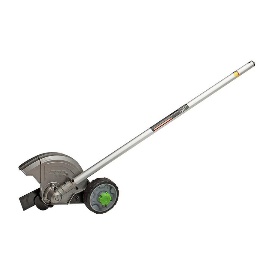
EGO EA0800 Repair Manual Line
String trimmer attachment
Hide thumbs
Also See for EA0800:
- Operator's manual (205 pages) ,
- Operator's manual (80 pages) ,
- Operator's manual (17 pages)

Related Manuals for EGO EA0800


Summary of Contents for EGO EA0800
- Page 1 REPAIR GUIDELINE String Trimmer Attachment_EA0800 Version: 1 Issue Date: 12/02/2016...
-
Page 2: Table Of Contents
Table of Contents Contents Page Troubleshooting Tool list Part 1: Replace the blade 5-15 Part 2: Replace the guide plate and the anti-wear protective guard 16-20 Part 3: Replace the wheel assembly 21-29... -
Page 3: Troubleshooting
Troubleshooting Fault Problem Possible Cause Test & Solution Position Noise No oil Gear case Add oil Replace the gear case with a new Doesn’t work Gear worn Gear case... -
Page 4: Tool List
Tool List For Repair Tool List SPEC Remark Needle-nose pliers Hex wrench Multi-function wrench 14mm... -
Page 5: Part 1: Replace The Blade
Part 1: Replace the blade... - Page 6 Replace the blade 1. Remove the split pin from the shaft with needle-nose pliers. Split pin Split pin Description Part Number Qty. Split pin 5670436001...
- Page 7 Replace the blade 2. Rotate the blade to align the slot in the flange with the hole in the gear case. 3. Insert the hex wrench into the aligned holes to act as a stabilizer.
- Page 8 Replace the blade 4. Loosen the nut clockwise with the multifunction wrench to remove it. Description Part Number Qty. 5630292001...
- Page 9 Replace the blade 5. Take the outer flange out of the shaft. 6. Take the blade out of the shaft. Outer flange Blade Description Part Number Qty. Outer flange 3552523001 Blade 3705431001...
- Page 10 Replace the blade 7. Take the inner flange out of the shaft. Inner flange Description Part Number Qty. Inner flange 3552522001...
- Page 11 Replace the blade 8. If any part is broken or worn replace it with a new one. 9. Mount the inner flange onto the shaft.
- Page 12 Replace the blade 10. Mount the blade onto the shaft. 11. Mount the nut onto the shaft and pre-tighten it anticlockwise.
- Page 13 Replace the blade 12. Rotate the blade to align the slot in the flange with the hole in the gear case. 13. Insert the hex wrench into the aligned holes to act as a stabilizer.
- Page 14 Replace the blade 14. Rotate the nut anticlockwise with multifunction wrench to tighten it.
- Page 15 Replace the blade 15. Insert a new split pin into the hole of the shaft. 16. Bend the two feet of the pin in opposite direction with long nose pliers.
-
Page 16: Part 2: Replace The Guide Plate And The Anti-Wear Protective Guard
Part 2: Replace the guide plate and the anti-wear protective guard... - Page 17 Replace the guide plate and the anti-wear protective guard 1. Loosen the screw on the guide plate to remove it. Guide plate screw Description Part Number Qty. Screw 5620018002 Guide plate 3705433001...
- Page 18 Replace the guide plate and the anti-wear protective guard 2. Loosen the screw on the anti-wear protective guard to remove it. Screw Anti-wear protective guard Description Part Number Qty. Screw 5620018002 Anti-wear protective guard 3705450001...
- Page 19 Replace the guide plate and the anti-wear protective guard 3. If the guide plate or anti-wear protective guard is broken, replace it with a new one. 4. Assemble the anti-wear protective guard with the shield with screw.
- Page 20 Replace the guide plate and the anti-wear protective guard 5. Assemble the guide plate with the anti-wear protective guard with screw.
-
Page 21: Part 3: Replace The Wheel Assembly
Part 3: Replace the wheel assembly... - Page 22 Replace the wheel assembly 1. Loosen the depth adjusting knob in the direction of the unlocking arrow marked on the knob and remove it. Depth adjusting knob Description Part Number Qty. Depth adjusting knob 3402815001...
- Page 23 Replace the wheel assembly 2. Take the spring washer and plain washer 1 out of the shaft in sequence. Spring washer Plain washer 1 Description Part Number Qty. Spring washer 5650026005 Plain washer 1 5650025001...
- Page 24 Replace the wheel assembly 3. Take the guide wheel out the screw pole. 4. Take the bush out of the screw pole. Bush Guide wheel Description Part Number Qty. Guide wheel 2824793001 Bush 3552519001...
- Page 25 Replace the wheel assembly 5. Remove plain washer 2 and screw pole. Screw pole Plain washer 2 Description Part Number Qty. Plain washer 2 5650025001 Screw pole 5640245001...
- Page 26 Replace the wheel assembly 6. If any part is broken, replace it with a new one. 7. Insert the screw pole into the hole of the depth-adjusting guide bar. 8. Mount the plain washer 2 onto the screw pole. Depth adjusting guide...
- Page 27 Replace the wheel assembly 9. Mount the bush onto the pole screw. 10. Mount the guide wheel onto the pole screw.
- Page 28 Replace the wheel assembly 11. Mount plain washer 2 and spring washer onto the pole screw in sequence.
- Page 29 Replace the wheel assembly 12. Mount the depth adjusting knob onto the screw pole and tighten it in the direction of the locking arrow marked on the knob.
Need help?
Do you have a question about the EA0800 and is the answer not in the manual?
Questions and answers