Advertisement
Quick Links
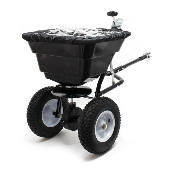
Instruction manual
Spreader GT1507
60910
Illustration similar, may vary depending on model
Please read and follow the operating instructions and safety information prior to initial operation.
Technical changes reserved!
Illustrations, functional steps and technical data may deviate insignificantly due to continuous further
developments.
Advertisement

Related Manuals for WilTec GT1507


Summary of Contents for WilTec GT1507
- Page 1 Instruction manual Spreader GT1507 60910 Illustration similar, may vary depending on model Please read and follow the operating instructions and safety information prior to initial operation. Technical changes reserved! Illustrations, functional steps and technical data may deviate insignificantly due to continuous further...
- Page 2 The information contained in this document may alter at any time without prior notice. No part of this document may be copied or otherwise duplicated without prior written consent. All rights reserved. WilTec Wildanger Technik GmbH cannot be held liable for any possible mistakes in this operating man- ual, nor in the diagrams and illustrations shown.
- Page 3 Before operating a vehicle on a slope (hill), you must respect the safety instructions of the user’s manual of the vehicle concerning safety on slopes. Do not drive on steep slopes! Open the packaging and pouch, remove all parts and check for completeness. © by WilTec Wildanger Technik GmbH Item 60910 Page 3 http://www.WilTec.de...
- Page 4 Assembly instructions step: 1. Mount the driving wheel (1) onto the drive and axle construction (3). 2. Insert the M4×20 fillister head screw (2) through the driving wheel and axle. © by WilTec Wildanger Technik GmbH Item 60910 Page 4 http://www.WilTec.de http://www.aoyue.eu...
- Page 5 3. Fix the mounting frame and foot to the hopper with M6×40 screws, M6 counter nuts and big washers ⌀6. Note: The screws and nuts do not need to be tightened yet. © by WilTec Wildanger Technik GmbH Item 60910 Page 5 http://www.WilTec.de...
- Page 6 2. Then mount the connecting rod to the wheel frame with a M6×60 screw (7) and M6 counter nut and fix the connecting plate to the connecting rod (1) with a M6×35 screw (6). Note: The screws and nuts do not need to be tightened. © by WilTec Wildanger Technik GmbH Item 60910 Page 6 http://www.WilTec.de...
- Page 7 3. Now mount the left wheel construction to the left axle inserting a ⌀16 washer, and mount the end cap on the left axle with a wooden or rubber mallet. © by WilTec Wildanger Technik GmbH Item 60910 Page 7 http://www.WilTec.de...
- Page 8 2. Now tighten all screws and bolts mounted from the first step on, but do not tighten them too strongly, then insert the R pin (2) to the front end for securing. © by WilTec Wildanger Technik GmbH Item 60910 Page 8 http://www.WilTec.de...
- Page 9 You can shift the position of the wing nut on the pressure gauge and lever to adjust the spacer of the three holes between the hopper and adjustable plate according to your needs. © by WilTec Wildanger Technik GmbH Item 60910 Page 9 http://www.WilTec.de...
- Page 10 Exploded view © by WilTec Wildanger Technik GmbH Item 60910 Page 10 http://www.WilTec.de http://www.aoyue.eu 2021-1 http://www.teichtip.de...
- Page 11 52 Spring washer ⌀6 26 Tow-bar connecting rod Important Note: Reproduction and any commercial use (of parts) of this operating manual, requires a written permission of WilTec Wildanger Technik GmbH. © by WilTec Wildanger Technik GmbH Item 60910 Page 11 http://www.WilTec.de http://www.aoyue.eu 2021-1 http://www.teichtip.de...
Need help?
Do you have a question about the GT1507 and is the answer not in the manual?
Questions and answers