Advertisement
Quick Links
Advertisement

Related Manuals for Goulds Pumps AF


Summary of Contents for Goulds Pumps AF
- Page 2 Operators and maintenance personnel must realize this and follow safety measures. Goulds pumps shall not be liable for physical injury, damage or delays caused by a failure to observe the instructions in this manual. The following symbols are used to denote special attention: Electrical Hazard.
- Page 3 FOREWORD This manual provides instructions for the Installation, operation, and maintenance of the Goulds Axial Flow (AF) pump model. This manual covers the standard product. For special options, supplemental instructions are supplied. This manual must be read and understood before installation and start-up.
- Page 4 This includes but is not limited to: 1. monitoring the pump frame and liquid end temperature 2. maintining proper bearing lubrication 3. ensuring that the pump is operated in the intended hydraulic range AF (42-66) IOM...
- Page 5 This includes any modification to the equipment or use of parts not provided by ITT/Goulds. If there is any question regarding the intended use of the equipment please contact an ITT/Goulds representative before proceeding. AF (42-66) IOM...
- Page 6 THIS PAGE INTENTIONALLY LEFT BLANK AF (42-66) IOM...
- Page 7 TABLE OF CONTENTS Page Section SAFETY GENERAL INFORMATION INSTALLATION OPERATION PREVENTATIVE MAINTENANCE DISASSEMBLY & RE-ASSEMBLY SPARE PARTS APPENDIX 1 AF (42-66) IOM...
- Page 8 THIS PAGE INTENTIONALLY LEFT BLANK AF (42-66) IOM...
- Page 9 GENERAL PRECAUTIONS WARNING Never run the pump < 75% or > 115% of the Best Efficiency Point (B.E.P.), AF pumps are unstable in Personal injury will result if procedures outlined in these regions. this manual are not followed. Always lock out power to the driver before performing maintenance.
- Page 10 THIS PAGE INTENTIONALLY LEFT BLANK AF (42-66) IOM...
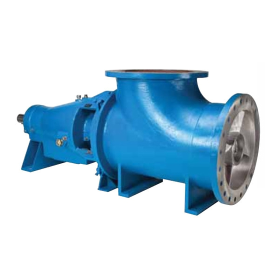
- Page 11 PUMP DESCRIPTION The AF pump generates flow by the thrust or lift Casing – The AF comes with a casing or spool piece to action of the rotating axial vanes of the impeller. It simplify impeller installation and alignment. The casing provides high flow rates and low heads which are bolts to the elbow and shrouds the impeller.
- Page 12 The nameplate for the AF is located on the number, and the item number of required parts. bearing housing. Note the format of the pump size: Information can be found in this manual.
- Page 13 Mech. seal adjusted per mfgr. Mfgrs Mnl Seal flush lines connected Impeller alignment and clearance set ______ Inch/Side Pump shaft-free turning Bearing lubrication 30, 38 V-belt or coupling guards installed 9, 22,30 Motor electrical connections Mfgrs Man’l AF (42-66) IOM...
- Page 14 THIS PAGE INTENTIONALLY LEFT BLANK AF (42-66) IOM...
-
Page 15: Table Of Contents
LOCATION/FOUNDATION AF pump shall be located in a clean, dry area free from The most commonly used foundation bolts are the flooding. The area should provide adequate space for sleeve-type (Fig 2 and J type Fig. -
Page 16: Sub-Base Leveling
4. Clean outside areas of sub-base that will contact grout. Do not use oil-based cleaners because grout will not bond to it. Refer to grout manufacturer's instructions. 5. Build a dam around foundation and thoroughly wet SHIMS OR WEDGES the foundation (Fig. 6). Fig. 5 AF (42-66) IOM... - Page 17 SPRING MOUNTED BASE BASEPLATE Fig. 8 shows a V-belt driven AF pump on a spring mounted sub-base. Sub-bases supported by spring BOLT pockets assure that the pump remains level, regardless of vertical movement due to thermal pipe GROU GROUT expansion during operation.
- Page 18 .812” 1140 #/in. 1-1/2”-6 UNC 190 # .750” 760 #/in. 1-1/2”-6 UNC 127 # .532” 560 #/in. 1-1/2”-6 UNC 93 # 1.00” 1000 #/in. 2”-4-1/2 UNC 222 # .375” 133 #/in. ¾”-10 UNC 13 # Table 1 AF (42-66) IOM...
-
Page 19: Connection Of Piping
Guidelines for piping are given in the “Hydraulic 2. Piping runs should be as short as possible to Institutes Standards” available from: Hydraulic minimize friction losses Institute, 30200 Detroit Road, Cleveland OH 44145- 1967 and must be reviewed prior to pump installation. AF (42-66) IOM... - Page 20 Suction lift conditions 1. Suction pipe must be free from air pockets. 2. Suction piping must slope upwards to pump. 3. All joints must be airtight. Suction head/Flooded suction conditions AF (42-66) IOM...
-
Page 21: Pipe Hung Installation
Pump must be Flanges must Extendable Pipe level .005”/ft be Parallel Guard Reduction Level Sub-base Horizontal Spool Piece Gear Drive Pipe Motor Shaft Flanges must Foundation Shaft Offset be Parallel +/- 1 to 3 deg. Fig. 11A AF (42-66) IOM... -
Page 22: Drive Alignment Procedures
Well designed and properly installed V-belt drives are Lock out driver power to prevent electric capable of running for years. AF pumps come in shock, accidental start-up and physical several different belt drive configurations i.e. side by injury. - Page 23 If the slack side remains taut during the peak load, the drive is too tight. Excessive bowing or slippage indicates insufficient tension. If the belts squeal as the motor begins operation or at some subsequent peak load, they are AF (42-66) IOM...
- Page 24 Keep this instruction manual handy for reference. Further information can be obtained by contacting Goulds Pumps, 240 Fall St., Seneca Falls, New York 13148 or your local representative. ALIGNMENT PROCEDURE On gear driven AF pumps angular and parallel...
- Page 25 When using positions 2 and 4 in steps 1 - 6, correct any misalignment by sliding the motor or gearbox back and forth to attain the proper alignment. AF (42-66) IOM...
- Page 26 180 from the start (3 o'clock), Observe the needle, measure and record the reading. 3. Make corrections as outlined previously. 4. Recheck both vertical and horizontal readings to ensure adjustment of one did not disturb the other. Correct as necessary. AF (42-66) IOM...
-
Page 27: Impeller Alignment
Clearance measurement - The alignment worksheet 4. Tighten the bolts between the casing and the on page 27 is used to align the impeller of the AF elbow and re-check the clearance to be sure the pump. The measurement procedure is as follows: adjustments have centered the impeller. - Page 28 (1.16 mm ) (0.58 mm ) AF (42-66) IOM...
-
Page 29: Rotation Check
A rotation arrow is located on the properly certified. bearing housing (134C). Serious damage could occur if the pump is run the wrong direction. AF (42-66) IOM... - Page 30 THIS PAGE INTENTIONALLY LEFT BLANK AF (42-66) IOM...
- Page 31 A check must be made to be sure motor rotation coincides with the pump rotation direction. Depending on your pump arrangement (V-belt or gear-drive) use one of the following methods to check motor rotation. AF (42-66) IOM...
- Page 32 Replace the breather. Table 2.shows the oil volume required. For a given speed and loading, the bearing housing temperature will stabilize at some temperature, usually AF (42-66) IOM...
- Page 33 6. Install the second and third coil as required by A packed stuffing box or mechanical seal is used to sectional drawing, staggering the cut 90 to 120 . seal the AF pump shaft. Both methods are described below. 7. Install the second lantern ring into stuffing box,...
- Page 34 Most mechanical seals are installed and adjusted at the factory. A common seal type used on the AF pump is the cartridge type. Cartridge seals are preset at the seal manufacturer’s facility and require no field settings. Due to size and design, some installed mechanical seals are supplied with holding clips.
- Page 35 The lubricating liquid must be clean and free of grit. Shaft scoring, packing destruction, and mechanical seal face damage will result from contaminated lubricant. AF (42-66) IOM...
- Page 36 Driver may overload if the pumpage circulation, care should be taken to maintain these specific gravity (density) is greater pumps in good operating condition. than originally assumed, or the rated flow rate is exceeded. AF (42-66) IOM...
- Page 37 On Liquid inside pump should be drained. small pumps, this effect is magnified as the percentage of impeller blade area lost from wear and corrosion is higher. AF (42-66) IOM...
- Page 38 FINAL ALIGNMENT 2. Check alignment per alignment procedure 1. Run the pump under actual conditions for a sufficient length of time to bring the pump and driver up to outlined earlier. operating temperature. AF (42-66) IOM...
- Page 39 If pump is Bearing lubrication being drained, precautions must be taken to prevent physical injury. Seal monitoring Pumpage must be handled and Vibration analysis disposed of in conformance with Discharge pressure applicable environment regulations. Temperature monitoring AF (42-66) IOM...
- Page 40 If the unit has an external oil lube system, fill the bearing housing and the reservoir to satisfy the system requirements. Replace the breather. Table 3. shows the oil volume required. AF (42-66) IOM...
- Page 41 Never operate the pump without liquid supplied to starting the pump. the mechanical seal. Running a mechanical seal dry, even for a few seconds, can cause seal damage and must be avoided. Physical injury can occur if the mechanical seal fails. AF (42-66) IOM...
- Page 42 Lip seals do not require any preventative maintenance but should be replaced during any rebuild operations. They can be cleaned occasionally from the outside by removing the slingers. INCORRECT CORRECT Fig. 18 AF (42-66) IOM...
- Page 43 Overheating mechanical seal Check lubrication and cooling lines Shaft sleeve scored Re-machine or replace as required Check head and flow, AF’s should normally be run between 75% and Pump run off design point 125% of BEP Packing has short life...
- Page 44 Check pump vibrations, if necessary rebalance impeller Excessive shaft deflection Check shaft diameter, sag and deflection, consult factory Check head and flow, AF’s should normally be run between 75% and Pump run off design point 125% of BEP Lubricant contamination...
- Page 45 Remove the impeller end cap (9988). Remove the screws (370C) that secure the impeller (101) and shaft washer (9985) to the shaft (122). Tapped holes in the hub of the impeller on the discharge side are provided for pulling the impeller AF (42-66) IOM...
- Page 46 3. Drain oil from bearing housing, disconnect oil circulation system, and remove pump from sub-base. 4. Wash down pump with appropriate cleaner. 5. Disassemble Pump per instructions per that section. Discharge piping and impeller (101) will be AF (42-66) IOM...
- Page 47 (136). Retighten locknut while components are cooling to keep them tight together. 6. Install (6) thrust bearings springs (9890) in thrust bearing retainer (109) or bearing housing (134) halves. Use thick grease in each hole to help hold springs until assembly. AF (42-66) IOM...
- Page 48 .002 in. (.05 mm) max. 2. Bearing seats and seal areas must be smooth and free of scratches and grooves. Shaft hole threads must be in good condition. Replace if necessary. AF (42-66) IOM...
- Page 49 Packing Gland (107) (Optional) Bearing Lockwasher (382) Bearing Locknut (136) HOW TO ORDER PARTS When ordering parts call 1-800-446-8537 or your local Goulds Representative EMERGENCY SERVICE Emergency parts service is available 24 hours a day, 365 days/year Call 1-800-446-8537 AF (42-66) IOM...
- Page 50 AF PARTS LIST–42-54 inch Pumps Item Part Description Item Part Description CASING STUD, GLAND PROPELLER HEX NUT, GLAND LANTERN RING 357D NUT, ELBOW TO CASING PACKING, PACKED BOX 358U PIPE PLUG [½-14 NPT] GLAND 358V PIPE PLUG [1”-11.5 NPT] RETAINER, THRUST BEARING 360X GASKET, BRG., OUTBOARD...
- Page 51 42–54 (Top Suction) AF with LMR Bearings Fig. 20 42–54 (End Suction) AF with LM Bearings Fig. 21 AF (42-66) IOM...
- Page 52 AF (42-66) IOM...
- Page 53 AF (42-66) IOM...
- Page 54 AF PARTS LIST–60-66 inch Top Suction Pumps Item Part Description Item Part Description CASING 357D HEX NUT, ELBOW TO CASING PROPELLER 358U PIPE PLUG [1/2-14 NPT] (NOT SHOWN) LANTERN RING 358V PIPE PLUG [1"-11.5 NPT] (NOT SHOWNl PACKING, PACKED BOX 360R GASKET, BRG.,...
- Page 55 60–66 (Top Suction) AF with LMR Bearings Fig. 24 AF (42-66) IOM...
- Page 56 AF (42-66) IOM...
- Page 57 AF PARTS LIST–60-66 inch End Suction Pumps Item Part Description Item Part Description CASING 357D HEX NUT, ELBOW TO CASING PROPELLER 358U PIPE PLUG [1/2-14 NPT] (NOT SHOWN) LANTERN RING 358V PIPE PLUG [1"-11.5 NPT] (NOT SHOWNl PACKING, PACKED BOX 360R GASKET, BRG.,...
- Page 58 60–66 (End Suction) AF with LM Bearings Fig. 26 AF (42-66) IOM...
- Page 59 AF (42-66) IOM...
- Page 60 THIS PAGE INTENTIONALLY LEFT BLANK AF (42-66) IOM...
- Page 61 For end suction pumps this will also include pump discharge pressure. Product flush pressure to the inner lantern ring may be slightly less than the water flush pressure to ensure flow toward the inside of the pump. AF (42-66) IOM...
- Page 62 Failure to property locate the lantern ring with respect to the flush ports will result in insufficient packing lubrication. Packing and shaft sleeve damage may result. AF (42-66) IOM...
- Page 63 THIS PAGE INTENTIONALLY LEFT BLANK...
- Page 64 Goulds Representative EMERGENCY SERVICE Emergency parts service is available 24 hours/day, 365 days/year . . . Call 1-800-446-8537 Visit our website at www.gouldspumps.com 2014 Goulds Pumps, Incorporated Form No. IAF (42-66) 04/14 a subsidiary of ITT Corporation...
Need help?
Do you have a question about the AF and is the answer not in the manual?
Questions and answers