
Related Manuals for Miller FILTAIR SWX-D


Summary of Contents for Miller FILTAIR SWX-D
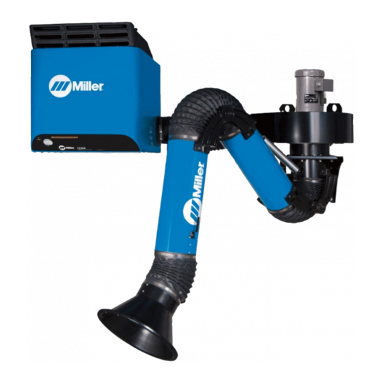
- Page 1 OM-246 877 D 2012−01 Description Stationary Weld Fume Extractor FILTAIR SWX-D And SWX-S Stationary Weld Fume Extractor Read And Save These Instructions File: Accessory Visit our website at www.MillerWelds.com...
- Page 2 We know you don’t have time to do it any other way. That’s why when Niels Miller first started building arc welders in 1929, he made sure his products offered long-lasting value and superior quality.
-
Page 3: Table Of Contents
TABLE OF CONTENTS SECTION 1 − SAFETY PRECAUTIONS - READ BEFORE USING ....... . . 1-1. -
Page 5: Section 1 − Safety Precautions - Read Before Using
SECTION 1 − SAFETY PRECAUTIONS - READ BEFORE USING fume 2011−10 Protect yourself and others from injury — read, follow, and save these important safety precautions and operating instructions. 1-1. Symbol Usage DANGER! − Indicates a hazardous situation which, if Indicates special instructions. -
Page 6: Arc Welding And Plasma Cutting Hazards
FALLING EQUIPMENT can injure. FIRE OR EXPLOSION hazard. D Use equipment of adequate capacity to lift and D Do not install or place unit on, over, or near support unit. combustible surfaces. D If using lift forks to move unit, be sure forks are D Do not install unit near flammables. - Page 7 D Do not use welder to thaw frozen pipes. FUMES AND GASES can be hazardous. D Remove stick electrode from holder or cut off welding wire at contact tip when not in use. Welding and cutting produces fumes and gases. D Wear oil-free protective garments such as leather gloves, heavy Breathing these fumes and gases can be hazardous shirt, cuffless trousers, high shoes, and a cap.
-
Page 8: Additional Symbols For Installation, Operation, And Maintenance
1-4. Additional Symbols For Installation, Operation, And Maintenance FIRE OR EXPLOSION hazard. BATTERY EXPLOSION can injure. D Do not install or place unit on, over, or near D Do not use welder to charge batteries or jump combustible surfaces. start vehicles unless the unit has a battery charging feature designed for this purpose. -
Page 9: California Proposition 65 Warnings
1-5. California Proposition 65 Warnings Welding or cutting equipment produces fumes or gases This product contains chemicals, including lead, known to which contain chemicals known to the State of California to the state of California to cause cancer, birth defects, or other cause birth defects and, in some cases, cancer. -
Page 10: Section 2 − Mesures De Sécurité
SECTION 2 − MESURES DE SÉCURITÉ − EXTRACTION DES FUMÉES − À LIRE AVANT UTILISATION fume_2011−10_fre Se protéger et protéger les autres contre le risque de blessure — lisez, appliquez et rangez en lieu sûr ces consignes importantes de sécurité et d’utilisation. 2-1. -
Page 11: Dangers Du Soudage À L'arc Et Du Coupage Au Plasma
D Lire et comprendre les instructions des fiches signalétiques et du Les PIÈCES MOBILES peuvent fabricant concernant les métaux, les consommables, les causer des blessures. revêtements, les nettoyants et les dégraisseurs. D L’extracteur de fumées doit être utilisé avec le bras d’extraction, D S’abstenir de toucher des organes mobiles tels les tuyaux, le filtre et les autres composants recommandés par le que des ventilateurs. - Page 12 D Ne pas enrouler les câbles autour du corps. D Portez un casque de soudage approuvé muni de verres filtrants D Si la pièce soudée doit être mise à la terre, le faire directement appropriés pour protéger visage et yeux contre les rayons et les avec un câble distinct.
-
Page 13: Dangers Supplémentaires En Relation Avec L'installation, Le Fonctionnement Et La Maintenance
D Ne jamais placer une torche de soudage sur une bouteille à gaz. DES PIECES DE METAL ou DES D Une électrode de soudage ne doit jamais entrer en contact avec SALETES peuvent provoquer des une bouteille. blessures dans les yeux. D Ne jamais souder une bouteille pressurisée −... - Page 14 D Tenir l’équipement (câbles et cordons) à distance des véhicules Les PIÈCES MOBILES peuvent mobiles lors de toute opération en hauteur. causer des blessures. D Suivre les consignes du Manuel des applications pour l’équation D S’abstenir de toucher des organes mobiles tels de levage NIOSH révisée (Publication Nº94–110) lors du levage que des ventilateurs.
-
Page 15: Proposition Californienne 65 Avertissements
2-5. Proposition californienne 65 Avertissements Les équipements de soudage et de coupage produisent des Ce produit contient des produits chimiques, notamment du fumées et des gaz qui contiennent des produits chimiques plomb, dont l’État de Californie reconnaît qu’ils provoquent dont l’État de Californie reconnaît qu’ils provoquent des mal- des cancers, des malformations congénitales ou d’autres formations congénitales et, dans certains cas, des cancers. -
Page 17: Section 3 − Definitions
SECTION 3 − DEFINITIONS 3-1. Symbols And Definitions Protective Earth Percent (Ground) Amperes Volts Air Filter SECTION 4 − SPECIFICATIONS 4-1. General Description The SWX stationary weld fume collection system consists of three primary components: extraction SWX-S Self-Cleaning Fume Extractor With Dual Extraction arm, blower assembly, and filter cabinet. -
Page 18: Specifications
4-2. Specifications A. Filter Cabinet (SWX-D Standard Model) Self-Cleaning Filter Area Inlet Size Inlets Mounting Weight Dimensions System System (L x W x H) 490 sq ft 6-3/4 in. ID Two (Left and Wall Bracket 130 lb 33 x 27-1/2 x 28-1/4 in. (45.5 m (171 mm) Right) -
Page 19: Section 5 − Installation
SECTION 5 − INSTALLATION 5-1. Serial Number And Rating Label Location The serial number and rating information is located on the left side of the unit. Use rating label to determine input power requirements and/or rated output. For future reference, write serial number in space provided on back cover of this manual. 5-2. -
Page 20: Preparing Filter Cabinet For Mounting
5-3. Preparing Filter Cabinet For Mounting Locking Bolts Mounting Bracket Loosen the two locking bolts and pivot mounting bracket away from cabinet. Remove bracket from cabin- et mounting forks. Tools Needed: 1/2 in. 248 231 OM-246 877 Page 16... -
Page 21: Preparing Filter Cabinet For Duct Work
5-4. Preparing Filter Cabinet For Duct Work Single Extraction Arm Installations Filter Cabinet Cover Plate Single Extraction Arm Installation Inlet Inlet Collar 1/4 in. Hardware The filter cabinet has left and right side inlets. Determine to which side of the cabinet the fumes will be duc- ted. -
Page 22: Installing Filter Cabinet Mounting Bracket
5-5. Installing Filter Cabinet Mounting Bracket Filter Cabinet See ceiling height require- Mounting ments in Section 4-2D. 42 in. (107 cm) Minimum Bracket Recommended For Filter (6 Holes) Removal Blower Mounting Bracket (6 Holes) 11-38 in. (29 cm) 26 − 38 in. (66 −... -
Page 23: Installation Guidelines For Large Diameter Tapcon (Ldt) Screw-Anchors
5-6. Installation Guidelines For Large Diameter Tapcon (LDT) Screw-Anchors Concrete And Metal Deck Installations Only qualified persons should in- stall, operate, maintain, and repair this unit. Installation must meet all Nation- al, State, and Local Codes − have only qualified persons make this installation. -
Page 24: Installing Filter Cabinet
5-7. Installing Filter Cabinet See Section 5-5 for mounting bracket installation. Tools Needed: 1/2 in. 248 231 during installation, use the attached ship- ing bracket. Lower the cabinet until both Installation must meet all National, ping pallet to lift unit. Remove pallet after forks are seated on bracket and within State, and Local Codes −... -
Page 25: Assembling Extraction Arm
5-8. Assembling Extraction Arm A. Attaching Elbow Brackets To Base Assembly And Installing Spring Elbow brackets are shipped Extraction Arm Elbow Bracket Part No. pre-assembled and torqued to 7 Ft 241 059 (R); 241 060 (L) the correct specifications. Veri- fy the part number on the 10 Ft. - Page 26 B. Assembling Extraction Arm Lower (Longer) Tube Be sure to install upper tube with spring bracket on top of tube and farthest from base as- sembly. Lower Tube Assembly Base Elbow Brackets 3/8 in. Screw 3/8 in. Flat Washer 3/8 in. Lock Washer 3/8 in.
- Page 27 C. Assembling Extraction Arm Upper Tube Brackets Elbow Bracket (Right) Extraction Arm Elbow Bracket Part No. Elbow Bracket (Left) 7 Ft 241 059 (R); 241 060 (L) Lower Tube Assembly 10 Ft. 241 059 (R); 241 060 (L) 3/8 in. Screw 12 Ft.
- Page 28 D. Assembling Extraction Arm Upper Tube Upper Tube Assembly Elbow Brackets 3/8 in. Screw 3/8 in. Flat Washer 3/8 in. Lock Washer 3/8 in. Nut Attach upper tube assembly to el- bow brackets with 3/8 in. hardware. Tighten hardware to 25 ft lb (34 N⋅m).
- Page 29 E. Assembling Extraction Arm Hood Tools Needed: 7/16 in. Ref. 805 386-B Hood Brackets ers, and nuts. Position fiber washers be- Flex duct (item 10) must be installed tween the square tube and upper tube 10 12 in. Flex Duct prior to installing hood.
- Page 30 F. Installing Flexible Duct Tools Needed: 5/16 in. 12 in. (30.5 cm) Flexible Duct to connect the joints. The three lengths in- the base assembly and the lower tube. Pull cluded are 12 in., 24 in., and 30 in. The 12 flex duct over tubes and securely tighten 24 in.
-
Page 31: Mounting Blower Assembly Bracket
5-9. Mounting Blower Assembly Bracket Filter Cabinet See ceiling height require- 42 in. (107 cm) Minimum Mounting ments in Section 4-2D. Recommended For Filter Bracket Removal (6 Holes) 1 − Blower Mounting Bracket (6 Holes) 11-38 in. (29 cm) 26 − 38 in. (66 −... -
Page 32: Installing Adapter On Blower Assembly
5-10. Installing Adapter On Blower Assembly Blower Assembly Adapter Remove the three screws from the blower housing discharge. Slide the adapter over the outlet and reinstall the three screws. Lower blower assembly onto mount- ing bracket so blower mounting flange is on top of bracket. Position blower so adapter is pointing toward filter cabinet. -
Page 33: Mounting Blower Assembly And Extraction Arm
5-11. Mounting Blower Assembly And Extraction Arm Installation must meet all Na- tional, State, and Local Codes − have only qualified persons make this installation. Do not use this equipment to support personnel, large tools, or other material. Be sure the wall or other struc- tural support will support the weight of the equipment. -
Page 34: Connecting Flexible Duct From Blower To Filter Cabinet
5-12. Connecting Flexible Duct From Blower To Filter Cabinet Be sure flexible duct is securely installed and does not leak. To reduce pressure loss, support Single Extraction Arm System flexible duct to eliminate bends. Connecting One Blower to Filter Cabinet Filter Cabinet Inlet Collar (See Section 5-4) 7 in. -
Page 35: Installing And Connecting Blower Control Panel (All Models)
5-13. Installing And Connecting Blower Control Panel (All Models) Installation must meet all Na- tional, State, and Local Codes. Have only qualified persons make this installation. Single Extraction Arm Installations A dedicated 115 volt AC, 15 Amp individual branch circuit protected by time delay (type D) fuses or cir- cuit breaker is required for each blower assembly. -
Page 36: Installing Cleaning System Control Panel (Swx-S Self-Cleaning Models Only)
5-14. Installing Cleaning System Control Panel (SWX-S Self-Cleaning Models Only) SWX-S Self-Cleaning Fume Extractor With Dual Extraction Arms Tools Needed: Phillips No. 2 247 867 / 248 234 / 248 235 Install control panel near the filter cabinet. If using a flexible cord and plug connection, Installation must meet all National use a 3-conductor, 14 AWG, UL listed hard State, and Local Codes. -
Page 37: Connecting To Compressed Air Supply (Swx-S Self-Cleaning Models Only)
5-15. Connecting To Compressed Air Supply (SWX-S Self-Cleaning Models Only) Shut off air supply before disconnecting or connecting air hose. Wear protective equipment SWX-S Self-Cleaning Fume Extractor when disconnecting com- With Dual Extraction Arms pressed air supply. Internal air tank is under pressure and will discharge when air supply is disconnected. -
Page 38: Section 6 − Operation
SECTION 6 − OPERATION 6-1. Controls On SWX-D Standard Models 247 867 / 245 608 / 228 000-D Filter Gauge Damper Control Only use the fume extractor to ex- tract weld fumes. Do not use the The damper allows the user to regulate air fume extractor to extract hot gases Gauge only indicates air pressure drop flow. -
Page 39: Controls On Swx-S Self-Cleaning Models
6-2. Controls On SWX-S Self-Cleaning Models 247 867 / 245 608 / 228 000-D / 248 234 Filter Gauge Particle Tray Only use the fume extractor to ex- tract weld fumes. Do not use the Empty tray after cleaning filter (see Section Gauge only indicates air pressure drop fume extractor to extract hot gases 7-4B). -
Page 40: Prestart Checklist (Before Welding)
6-3. Prestart Checklist (Before Welding) Do not use the fume extrac- tion equipment unless you are sure it is correctly as- sembled and working prop- erly. SWX-S Self-Cleaning Models Check for free and easy move- ment of the extraction arm and swivel base before each use. -
Page 41: Section 7 − User Servicing Instructions (Maintenance)
SECTION 7 − USER SERVICING INSTRUCTIONS (MAINTENANCE) 7-1. Routine Maintenance Disconnect Power before maintaining. Service equipment more often if used in severe conditions. To make cleaning easier, apply anti-spatter spray to the extraction hood. n = Check Z = Change ~ = Clean l = Replace * To be done by Factory Authorized Service Agent... -
Page 42: Overload Protection
7-2. Overload Protection Turn off and disconnect input power. If a fuse or circuit breaker opens, it usually indicates a more serious problem exists. Contact a Factory Authorized Service Agent. Circuit Breaker CB1 (All Models) CB1 protects the blower motor from overload. -
Page 43: Servicing Filter And Spark Guard (Swx-D Models)
7-3. Servicing Filter And Spark Guard (SWX-D Models) Turn off and disconnect input power. Do not operate unit without fil- ter or with dirty filter. Replace the filter when dirty. Do not clean the filter or use a filter that has been cleaned. Do not breathe the particles collected by the fume extrac- tor. -
Page 44: Servicing Filter And Spark Guard (Swx-S Self-Cleaning Models Only)
7-4. Servicing Filter And Spark Guard (SWX-S Self-Cleaning Models Only) A. Inspecting Filter And Spark Guard (SWX-S Self-Cleaning Models Only) Turn off power and discon- nect input power cord. Do not operate unit without fil- ter or with dirty filter. Clean or replace the filter when dirty. - Page 45 B. Cleaning Filter And Emptying Particle Tray (SWX-S Self-Cleaning Models Only) Close cover before starting unit or operating filter cleaning sys- tem. Do not operate unit without filter or with dirty filter. Clean or replace filter when dirty. Do not breathe the particles col- lected by the fume extractor.
-
Page 46: Adjusting Extraction Arm Joints
7-5. Adjusting Extraction Arm Joints Support extraction when making adjustments. Elbow joints are under ten- sion. Keep away from pinch points when making adjust- ments. The joints are secured with a double-nut system; the jam nut (outer) secures the inside nut. When properly adjusted, the ex- traction arm should move easily but not slip from position. -
Page 47: Section 8 − Troubleshooting
SECTION 8 − TROUBLESHOOTING 8-1. Troubleshooting Table Trouble Remedy Motor/blower will not start or continue Check input power connections (Section 5-13). running. Reset Circuit Breaker CB1 (See Section 7-2) Have Factory Authorized Service Agent check motor and wiring. Decreased air flow. Reconnect extraction arm flexible tubing. -
Page 48: Section 9 − Electrical Diagrams
SECTION 9 − ELECTRICAL DIAGRAMS Figure 11-1. Circuit Diagram For SWX-D (Standard Model) OM-246 877 Page 44... - Page 49 249 232-B OM-246 877 Page 45...
- Page 50 Figure 11-2. Circuit Diagram For SWX-S (Self-Cleaning Model) OM-246 877 Page 46...
- Page 51 246 882-B OM-246 877 Page 47...
-
Page 52: Section 10 − Parts List
SECTION 10 − PARTS LIST Hardware is common and not available unless listed. 248 192 Figure 10-1. SWX-D Filter Cabinet OM-246 877 Page 48... - Page 53 Item Dia. Part Mkgs. Description Quantity Figure 10-1. SWX-D Filter Cabinet ....247764 ..Bracket, Locking Mount Wdt ........
- Page 54 Hardware is common and not available unless listed. 10 − See Figure 10-3 248 193 Figure 10-2. SWX-S (Self-Cleaning) Filter Cabinet OM-246 877 Page 50...
- Page 55 Item Dia. Part Mkgs. Description Quantity Figure 10-2. SWX-S (Self-Cleaning) Filter Cabinet ....247764 Bracket, Locking Mount Wdt ........
- Page 56 Hardware is common and not available unless listed. 245 653 Figure 10-3. Self-Cleaning Assembly Item Dia. Part Mkgs. Description Quantity Figure 10-3. Self-Cleaning Assembly (Figure 10-2, Item 10 ) ....245248 Pulley, Timing Belt 1.783 Od 1/5 Pitch .906 Bore .
- Page 57 Hardware is common and not available unless listed. Control Panel 248 226 / 248 032 Figure 10-4. Blower Assembly And Blower Control Panel OM-246 877 Page 53...
- Page 58 Item Dia. Part Mkgs. Description Quantity Figure 10-4. Blower Assembly And Blower Control Panel ... . . 241939 Motor, Blower 1hp 3450rpm Tefc 115/1/60/56c (Includes) ....
- Page 59 Hardware is common and not available unless listed. 246 879 Figure 10-5. Control Panel − SWX-S Models Item Dia. Part Mkgs. Description Quantity Figure 10-5. Control Panel − SWX-S Models ....248186 Assembly, Control Panel Self−clean (Includes) .
- Page 60 Hardware is common and not available unless listed. 248 225 / 805 386 / 805 268 Figure 10-6. Extraction Arm Assembly Item Dia. Part Mkgs. Description Quantity Figure 10-6. Extraction Arm Assemblies ....248046 Swing Arm Assy, Base 8 in (Includes) .
- Page 61 Item Dia. Part Mkgs. Description Quantity Figure 10-6. Extraction Arm Assemblies (Continued) ....248056 Spring, Supporting SA-W807 7 Ft ........
- Page 62 Item Dia. Part Mkgs. Description Quantity Figure 10-6. Extraction Arm Assemblies (Continued) ......Damper (Parts Only Sold Separately) .
- Page 63 Effective January 1, 2012 (Equipment with a serial number preface of MC or newer) This limited warranty supersedes all previous Miller warranties and is exclusive with no other Warranty Questions? guarantees or warranties expressed or implied. LIMITED WARRANTY − Subject to the terms and conditions 90 Days —...
- Page 64 Contact the Delivering Carrier to: File a claim for loss or damage during shipment. For assistance in filing or settling claims, contact your distributor and/or equipment manufacturer’s Transportation Department. © ORIGINAL INSTRUCTIONS − PRINTED IN USA 2012 Miller Electric Mfg. Co. 2012−01...
Need help?
Do you have a question about the FILTAIR SWX-D and is the answer not in the manual?
Questions and answers