Table of Contents
Advertisement
Advertisement
Table of Contents

Related Manuals for Miller FILTAIR SWX-S


Summary of Contents for Miller FILTAIR SWX-S
- Page 1 OM-246877K 2019−05 Description Stationary Weld Fume Extractor FILTAIR SWX-D And SWX-S Stationary Weld Fume Extractor Read And Save These Instructions File: Accessory For product information, Owner’s Manual translations, and more, visit www.MillerWelds.com...
- Page 2 1929, he made sure his products offered long-lasting value and superior quality. Like you, his customers couldn’t afford anything less. Miller products had to be more than the best they could be. They had to be the best you could buy.
-
Page 3: Table Of Contents
TABLE OF CONTENTS SECTION 1 − SAFETY PRECAUTIONS - READ BEFORE USING ....... . . 1-1. -
Page 5: Section 1 − Safety Precautions - Read Before Using
SECTION 1 − SAFETY PRECAUTIONS - READ BEFORE USING fume 2019−02 Protect yourself and others from injury — read, follow, and save these important safety precautions and operating instructions. 1-1. Symbol Usage DANGER! − Indicates a hazardous situation which, if Indicates special instructions. -
Page 6: Arc Welding And Plasma Cutting Hazards
FALLING EQUIPMENT can injure. FIRE OR EXPLOSION hazard. D Use correct procedures and equipment of ade- D Do not install or place unit on, over, or near quate capacity to lift and support unit. combustible surfaces. D If using lift forks to move unit, be sure forks are D Do not install unit near flammables. - Page 7 D Do not weld or cut on containers that have held combustibles, or on FUMES AND GASES can be hazardous. closed containers such as tanks, drums, or pipes unless they are properly prepared according to AWS F4.1 and AWS A6.0 (see Welding and cutting produces fumes and gases.
-
Page 8: Additional Symbols For Installation, Operation, And Maintenance
NOISE can damage hearing. ELECTRIC AND MAGNETIC FIELDS (EMF) can affect Implanted Medical Devices. Noise from some processes or equipment can damage hearing. D Wearers of Pacemakers and other Implanted Medical Devices should keep away. D Wear approved ear protection if noise level is high. -
Page 9: California Proposition 65 Warnings
ARC WELDING AND PLASMA CUTTING can READ INSTRUCTIONS. cause interference. D Read and follow all labels and the Owner’s D Electromagnetic energy can interfere with Manual carefully before installing, operating, or sensitive electronic equipment such as servicing unit. Read the safety information at computers and computer-driven equipment the beginning of the manual and in each such as robots. -
Page 10: Section 2 − Mesures De Sécurité − Extraction Des Fumées − À Lire Avant Utilisation
SECTION 2 − MESURES DE SÉCURITÉ − EXTRACTION DES FUMÉES − À LIRE AVANT UTILISATION fume_2019−02_fre Se protéger et protéger les autres contre le risque de blessure — lisez, appliquez et rangez en lieu sûr ces consignes importantes de sécurité et d’utilisation. 2-1. -
Page 11: Dangers Du Soudage À L'arc Et Du Coupage Au Plasma
D Remplacer le filtre s’il est endommagé ou bloqué. Attendre que le D Tenir l’équipement (câbles et cordons) à distance des véhicules filtre se refroidisse avant de l’inspecter ou de le remplacer, ou de mobiles lors de toute opération en hauteur. nettoyer les particules accumulées sur le pare−étincelles. - Page 12 élevé de contact inévitable ou accidentel avec la pièce à souder ou D À l’intérieur, ventiler la zone et/ou utiliser une ventilation forcée au niveau de l’arc pour l’évacuation des fumées et des gaz de le sol. Dans ces conditions, utiliser les équipements suivants, dans soudage.
-
Page 13: Dangers Supplémentaires En Relation Avec L'installation, Le Fonctionnement Et La Maintenance
D Ne pas couper ou souder des jantes ou des roues. Les pneus LES BOUTEILLES peuvent exploser peuvent exploser s’ils sont chauffés. Les jantes et les roues si elles sont endommagées. réparées peuvent défaillir. Voir OSHA 29 CFR 1910.177 énuméré dans les normes de sécurité. - Page 14 D Tenir l’équipement (câbles et cordons) à distance des véhicules L’AIR COMPRIMÉ risque de provoquer mobiles lors de toute opération en hauteur. des blessures ou même la mort. D Suivre les consignes du Manuel des applications pour l’équation de levage NIOSH révisée (Publication Nº94–110) lors du levage D Avant d’intervenir sur le circuit d’air comprimé, manuelle de pièces ou équipements lourds.
-
Page 15: Proposition Californienne 65 Avertissements
LE SOUDAGE À L’ARC ET LE RAYONNEMENT HAUTE COUPAGE PLASMA risquent de FRÉQUENCE (H.F.) risque provoquer des interférences. provoquer des interférences. D Le rayonnement haute fréquence (H.F.) peut D L’énergie électromagnétique peut gêner le provoquer des interférences avec les équi- fonctionnement d’appareils électroniques sen- pements de radio−navigation et de com- sibles comme des ordinateurs et des équi-... -
Page 16: Section 3 − Definitions
SECTION 3 − DEFINITIONS 3-1. Symbols And Definitions Protective Earth Percent (Ground) Alternating Current Amperes Volts Air Filter (AC) Input Plug And Rated Supply Rated Supply Horsepower Cord Voltage Current Notes Work like a Pro! Pros weld and cut safely. Read the safety rules at the beginning of this manual. -
Page 17: Section 4 − Specifications
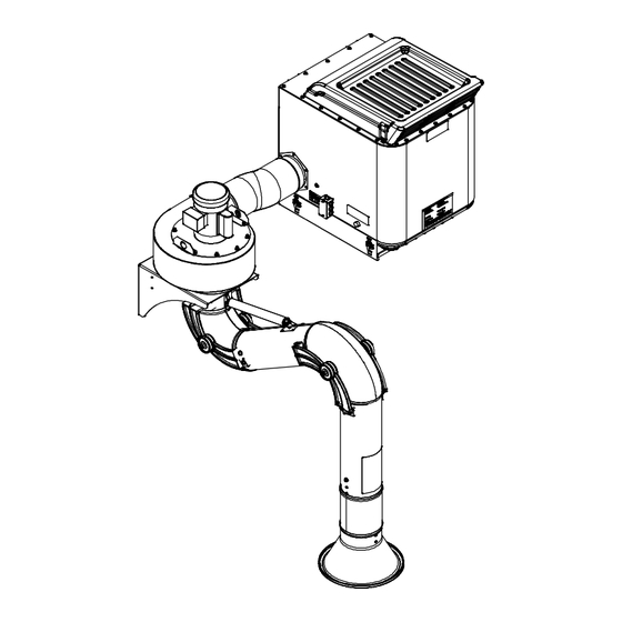
SECTION 4 − SPECIFICATIONS 4-1. Introduction The SWX stationary weld fume collection system consists of three primary components: extraction SWX-S Self-Cleaning Fume Extractor arm, blower assembly, and filter cabinet. With Dual Extraction Arms The extraction arm uses locking joints and flex- ible tubing to ensure the hood is placed near the source of the fumes. - Page 18 D. Standard Extraction Arm Specifications Model Arm Reach Arm Diameter Arm Weight Hood Diameter Recommended Minimum Ceiling Mounting Height Height SA−W8T 3 − 4.5 ft 8 in. (200 mm) 22 lb (10 kg) 8 ft (2.4 m) 12 ft, 4 in. (3.8 m) (8 in.
-
Page 19: Environmental Specifications
E. ZoneFlowt Extraction Arm Specifications Model Arm Reach Arm Diameter Recommended Minimum Ceiling Height Mounting Height SA-W610-ZF-WM 10 ft (3 m) 6 in. (200 mm) 8 ft (2.4 m) 13 ft 4 in. (3.8 m) SA-W612-ZF-WM 12 ft (3.7 m) 6 in. -
Page 20: Section 5 − Installation
SECTION 5 − INSTALLATION 5-1. Selecting A Location Only qualified persons should install, operate, maintain, and repair this unit. Installation must meet all National, State, and Local Codes − have only qualified persons make this installation. Do not move or operate unit where it could tip. -
Page 21: Preparing Filter Cabinet For Mounting
5-2. Preparing Filter Cabinet For Mounting Locking Bolts Mounting Bracket Loosen the two locking bolts and pivot mounting bracket away from cabinet. Remove bracket from cabin- et mounting forks. Tools Needed: 1/2 in. 248 231 OM-246877 Page 17... -
Page 22: Preparing Filter Cabinet For Duct Work
5-3. Preparing Filter Cabinet For Duct Work Single Extraction Arm Installations Filter Cabinet Cover Plate Single Extraction Arm Inlet Installation Inlet Collar 1/4 in. Hardware The filter cabinet has left and right side inlets. Determine to which side of the cabinet the fumes will be duc- ted. -
Page 23: Installing Filter Cabinet And Blower Assembly Mounting Brackets
5-4. Installing Filter Cabinet And Blower Assembly Mounting Brackets Filter Cabinet See ceiling height requirements Mounting Bracket in Section 4-3D. 42 in. (107 cm) Minimum (6 Holes) Recommended For Filter Removal Blower Mounting Bracket (6 Holes) 11 in. 28 cm 26 −... -
Page 24: Filter Cabinet Mounting Bracket Hole Pattern
5-5. Filter Cabinet Mounting Bracket Hole Pattern 16.040 15.665 14.915 14.020 2.020 1.125 .940 247746-A 5-6. Blower Mounting Bracket Hole Pattern 14.000 REF 8.000 3.000 1.000 TYP .500 REF 12.000 REF 8.000 1.000 1.000 TYP 1.750 REF 247750-A OM-246877 Page 20... -
Page 25: Installing Filter Cabinet
5-7. Installing Filter Cabinet See Section 5-4 for mounting bracket installation. Tools Needed: 1/2 in. 248 231 Installation must meet all National, ping pallet to lift unit. Remove pallet after forks are seated on bracket and within State, and Local Codes − have only completing installation. -
Page 26: Installing Adapter On Blower Assembly
5-8. Installing Adapter On Blower Assembly Blower Assembly Adapter Remove the three screws from the blower housing discharge. Slide the adapter over the outlet and reinstall the three screws. Lower blower assembly onto mount- ing bracket so blower mounting flange is on top of bracket. Position blower so adapter is pointing toward filter cabinet. -
Page 27: Mounting Single Blower Assembly And Extraction Arm
5-9. Mounting Single Blower Assembly And Extraction Arm Installation must meet all Na- tional, State, and Local Codes − have only qualified persons make this installation. Do not use this equipment to support personnel, large tools, or other material. Be sure the mounting hard- ware and the wall or other structure will support the weight of the equipment. -
Page 28: Mounting Dual Blower Assemblies And Extraction Arms
5-10. Mounting Dual Blower Assemblies And Extraction Arms Installation must meet all Na- tional, State, and Local Codes − have only qualified persons make this installation. Do not use this equipment to support personnel, large tools, or other material. Be sure the mounting hard- ware and the wall or other structure will support the weight of the equipment. -
Page 29: Connecting Flexible Duct From Blower To Filter Cabinet
5-11. Connecting Flexible Duct From Blower To Filter Cabinet Be sure flexible duct is securely installed and does not leak. To reduce pressure loss, support flexible duct to eliminate bends. Single Extraction Arm System Connecting One Blower to Filter Cabinet Filter Cabinet Inlet Collar (See Section 5-3) 7 in. -
Page 30: Installing And Connecting Blower Control Panel (All Models)
5-12. Installing And Connecting Blower Control Panel (All Models) Installation must meet all Na- tional, State, and Local Codes. Have only qualified persons make this installation. Single Extraction Arm Disconnect and lockout/tagout Installations input power before connecting input conductors from unit. Follow established procedures regarding the installation and removal of lockout/tagout de-... -
Page 31: Installing Cleaning System Control Panel (Swx-S Self-Cleaning Models Only)
5-13. Installing Cleaning System Control Panel (SWX-S Self-Cleaning Models Only) SWX-S Self-Cleaning Fume Extractor With Dual Extraction Arms Tools Needed: Phillips No. 2 247 867-B / 248 234 / 248 235 Installation must meet all National Cleaning System Control Panel For a permanent connection, use 1/2 in. -
Page 32: Connecting To Compressed Air Supply (Swx-S Self-Cleaning Models Only)
5-14. Connecting To Compressed Air Supply (SWX-S Self-Cleaning Models Only) Shut off air supply before dis- connecting or connecting air hose. Wear protective equipment when disconnecting com- SWX-S Self-Cleaning Fume Extractor pressed air supply. Internal air With Dual Extraction Arms tank is under pressure and will discharge when air supply is disconnected. -
Page 33: Section 6 − Operation
SECTION 6 − OPERATION 6-1. Controls On SWX-D Standard Models 247 867 / 245 608 / 248233-A Only use the fume extractor to ex- Minimize cross drafts that affect gauge should read between 0.1 and 0.5 in. tract weld fumes. Do not use the fume extraction by closing doors/ w.c. -
Page 34: Controls On Swx-S Self-Cleaning Models
6-2. Controls On SWX-S Self-Cleaning Models 247 867-B / 245 608 / 248233-A / 248 234 Only use the fume extractor to ex- Power Switch Particle Tray tract weld fumes. Do not use the Use switch to turn unit On and Off. The fume extractor to extract hot gases Empty tray after cleaning filter (see Section Power switch is located on a control panel... -
Page 35: Prestart Checklist (Before Welding)
6-3. Prestart Checklist (Before Welding) Do not use the fume extrac- tion equipment unless you are sure it is correctly assembled and working properly. SWX-S Self-Cleaning Models Check for free and easy move- ment of the extraction arm and swivel base before each use. Clean Air Outlet Filter Gauge Verify all duct work and tubing is... -
Page 36: Section 7 − User Servicing Instructions (Maintenance)
SECTION 7 − USER SERVICING INSTRUCTIONS (MAINTENANCE) 7-1. Routine Maintenance Disconnect and lockout/tagout input power before servicing. Follow established procedures regarding the installation and removal of lockout/tagout devices. Service equipment more often if used in severe conditions. n = Check Z = Change ~ = Clean l = Replace... -
Page 37: Overload Protection
7-2. Overload Protection Disconnect and lockout/tagout input power before connecting input conductors from unit. Fol- low established procedures re- garding the installation and re- moval of lockout/tagout devices. If a fuse or circuit breaker opens, it usually indicates a more serious problem exists. -
Page 38: Servicing Filter And Spark Guard (Swx-D Models)
7-3. Servicing Filter And Spark Guard (SWX-D Models) Disconnect and lockout/tag- out input power before con- necting input conductors from unit. Follow established pro- cedures regarding the installa- tion and removal of lockout/ tagout devices. Do not operate unit without fil- ter or with dirty (plugged) filter. -
Page 39: Servicing Filter And Spark Guard (Swx-S Self-Cleaning Models Only)
7-4. Servicing Filter And Spark Guard (SWX-S Self-Cleaning Models Only) A. Inspecting Filter And Spark Guard (SWX-S Self-Cleaning Models Only) Disconnect and lockout/tag- out input power before con- necting input conductors from unit. Follow established procedures regarding the in- stallation and removal of lockout/tagout devices. - Page 40 B. Cleaning Filter And Emptying Particle Tray (SWX-S Self-Cleaning Models Only) Close cover before starting unit or operating filter cleaning sys- tem. Do not operate unit without filter or with dirty (plugged) filter. Clean or replace filter when dirty (plugged). Allow cooling period before in- specting or replacing filter, or cleaning particle tray and spark...
-
Page 41: Section 8 − Troubleshooting
SECTION 8 − TROUBLESHOOTING 8-1. Troubleshooting Table Trouble Remedy Motor/blower will not start or continue Check input power connections (Section 5-12). running. Reset Circuit Breaker CB1 (See Section 7-2) Have Factory Authorized Service Agent check motor and wiring. Decreased air flow. Reconnect extraction arm flexible tubing. -
Page 42: Section 9 − Electrical Diagrams
SECTION 9 − ELECTRICAL DIAGRAMS For SWX-S self-cleaning models, see Figure 9-2. Motor must be wired for reverse (CCW) rotation. See Owner’s Manual 279913 for information on the ZoneFlow module (if equipped). Ref. 249 232-B Figure 9-1. Circuit Diagram For SWX-D (Standard Model) Motor must be wired for reverse (CCW) rotation. - Page 43 Ref. 249 232-B Figure 9-3. Circuit Diagram For Light Kit Option OM-246877 Page 39...
-
Page 44: Section 10 − Parts List
SECTION 10 − PARTS LIST Hardware is common and not available unless listed. See extraction arm owner’s manual for installation and service information. 248 192 Figure 10-1. SWX-D Filter Cabinet OM-246877 Page 40... - Page 45 Item Dia. Part Mkgs. Description Quantity Figure 10-1. SWX-D Filter Cabinet ....247764 ..Bracket, Locking Mount Wdt ........
- Page 46 Hardware is common and not available unless listed. 10 − See Figure 10-3 248 193 Figure 10-2. SWX-S (Self-Cleaning) Filter Cabinet OM-246877 Page 42...
- Page 47 Item Dia. Part Mkgs. Description Quantity Figure 10-2. SWX-S (Self-Cleaning) Filter Cabinet ....247764 Bracket, Locking Mount Wdt ........
- Page 48 Hardware is common and not available unless listed. 245 653-B Figure 10-3. Self-Cleaning Assembly Item No. Part No. Description Quantity Figure 10-3. Self-Cleaning Assembly (Figure 10-2, Item 10) ....245248 Pulley, Timing Belt 1.783 OD 1/5 Pitch .906 Bore .
- Page 49 Hardware is common and not available unless listed. Control Panel 248 226-B / 248 032 Figure 10-4. Blower Assembly And Blower Control Panel OM-246877 Page 45...
- Page 50 Item Dia. Part Mkgs. Description Quantity Figure 10-4. Blower Assembly And Blower Control Panel ....247731 Assy, Blower Housing (Includes) ........
- Page 51 Hardware is common and not available unless listed. 246 879 Figure 10-5. Control Panel − SWX-S Models Item Dia. Part Mkgs. Description Quantity Figure 10-5. Control Panel − SWX-S Models ....248186 Assembly, Control Panel Self−clean (Includes) .
- Page 55 Effective January 1, 2019 (Equipment with a serial number preface of MK or newer) This limited warranty supersedes all previous Miller warranties and is exclusive with no other guarantees or warranties expressed or implied. LIMITED WARRANTY − Subject to the terms and conditions Subarc Wire Drive Assemblies below, Miller Electric Mfg.
- Page 56 Contact the Delivering Carrier to: File a claim for loss or damage during shipment. For assistance in filing or settling claims, contact your distributor and/or equipment manufacturer’s Transportation Department. ORIGINAL INSTRUCTIONS − PRINTED IN USA 2019 Miller Electric Mfg. LLC 2019−01...
Need help?
Do you have a question about the FILTAIR SWX-S and is the answer not in the manual?
Questions and answers