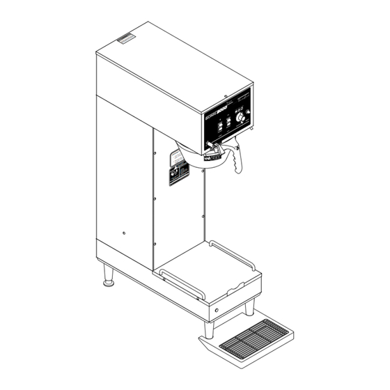
Bunn Single TF Operating & Service Manual
1.75 gallon
Hide thumbs
Also See for Single TF:
- Operating & service manual (47 pages) ,
- Illustrated parts catalog (35 pages) ,
- Use & care information manual (6 pages)
Table of Contents
Advertisement
Quick Links
BUNN
OPERATING & SERVICE MANUAL
BUNN-O-MATIC CORPORATION
27118.0000C 10/00 ©1996 Bunn-O-Matic Corporation
POST OFFICE BOX 3227
SPRINGFIELD, ILLINOIS 62708-3227
PHONE: (217) 529-6601 FAX: (217) 529-6644
®
SINGLE
E R
A T
T W
H O
N
U T
IO
E S
C A
U R
!
E D
O C
P R
IN G
e if
A T
s iz
w .
b re
E R
e r
e rv
to
O P
e s
k S
e c
fu s
C h
r re
w e
°
1 .
w
± 5
B re
B re
°F
ld 's
0 0
n a
: 2
D o
tu re
M c
e ra
2 .
m p
6 )
T e
8 -9
N
E R
(3 -1
N T
IO
C A
U T
D E
R D
C A
C A
D IS
!
IF :
E D
C K
D
TY
H E
M P
R A
A TC
D R
Y
N E
A M
E
. C
C R
H E
IC
. S
E D
H FL
C TR
O IL
D W
IG
. B
TE
N H
E LE
E A
D O
E D
. H
O S
S E
X P
. U
R E
N TS
M E
Y
. O
U R
E LE
IN J
T S
IO
N
E N
K S
AT
OR
N T
R IS
RP
C O
L Y
IC
CO
O T
AT
E L
M P
-M
N N
E H
C O
NN
-O
A R
BU
F U
T O
85
R E
19
IL U
F A
8
: 65
PN
™
1.75 GALLON
TF
Advertisement
Table of Contents

Subscribe to Our Youtube Channel
Related Manuals for Bunn Single TF


Summary of Contents for Bunn Single TF
- Page 1 BUNN OPERATING & SERVICE MANUAL BUNN-O-MATIC CORPORATION PHONE: (217) 529-6601 FAX: (217) 529-6644 27118.0000C 10/00 ©1996 Bunn-O-Matic Corporation ® IN G e if s iz b re e rv fu s r re ° ± 5 B re B re °F...
-
Page 2: Warranty
SPECIFIED HEREIN, TO REPAIR OR, AT BUNN’S SOLE OPTION, REPLACEMENT OR REFUND. In no event shall Bunn be liable for any other damage or loss, including, but not limited to, lost profits, lost sales, loss of use of equipment, claims of Buyer’s customers, cost of capital, cost of down time, cost of substitute equipment, facilities or services, or any other special, incidental or consequential damages. -
Page 3: Electrical Requirements
USER NOTICES The notices on this brewer should be kept in good condition. Replace unreadable or damaged labels. 00658.0000 WARNING HOT WATER 20201.5600 ELECTRICAL REQUIREMENTS CAUTION - The brewer must be disconnected from the power source until specified in Initial Set-Up. WHITE NEUTRAL 120V.A.C. -
Page 4: Plumbing Requirements
" water supply line. A tight coil of copper tubing in the water line will facilitate moving the brewer to clean the countertop. Bunn-O-Matic does not recommend the use of a saddle valve to install the brewer. The size and shape of the hole made in the supply line by this type of device may restrict water flow. -
Page 5: Initial Setup
INITIAL SET-UP CAUTION – The brewer must be disconnected from the power source throughout the initial set-up, except when specified in the instructions. NOTE: ECA Models Only - This brewer is equipped with a temperature sensor that indicates when to brew and, when selected, locks-out the start of a brew cycle until the water has heated to the optimum brewing temperature. -
Page 6: Adjusting Brew Volumes
ADJUSTING BREW VOLUMES CAUTION - Disconnect the power source from the brewer prior to the removal of any panel for the replacement or adjustment of any component. NOTE: Prior to setting or modifying batch sizes, check that the brewer is connected to water supply, the tank is properly filled, and a funnel and server are in place. -
Page 7: Operating Controls
NOTE: The On/Off switch must be in the lighted upper position to initiate and complete a brew cycle. COFFEE BREWING 1. Select the desired batch size. 2. Insert a BUNN ® filter into the funnel. 3. Pour the proper amount of fresh coffee into the filter and level the bed of grounds by gently shaking. -
Page 8: Troubleshooting
TROUBLESHOOTING A troubleshooting guide is provided to suggest probable causes and remedies for the most likely problems encountered. If the problem remains after exhausting the troubleshooting steps, contact the Bunn-O-Matic Technical Service Department. • Inspection, testing, and repair of electrical equipment should be performed only by qualified service personnel. - Page 9 TROUBLESHOOTING (cont.) Problem Brew cycle will not start (cont.) Automatic refill will not operate Probable Cause 3. Water strainer/flow control (.500 GPM) 4. ON/OFF switch 5. Start switch 6. Timer 7. Dispense Valve 8. Control Assembly (Electronic) 9. Brew selector switch 10.
-
Page 10: Table Of Contents
TROUBLESHOOTING (cont.) Problem Automatic refill will not operate (cont.) Beverage level will not adjust (Selec- tor switch in any position) Water flows into tank continuously (ON/OFF Switch "ON") Water flows into tank continuously (ON/OFF Switch "OFF") Water from tank is not hot Probable Cause 3. -
Page 11: Thru 27
TROUBLESHOOTING (cont.) Problem Water from tank is not hot (cont.) Spitting or unusual steaming from sprayhead or airvent. Probable Cause 2. (A) Control Thermostat (Electro/ mechanical) (B) Control assembly (Electronic) 3. Contactor (Electro/mechanical) 4. Tank heater 5. Triac assembly (Electronic) 1. -
Page 12: Testing Procedures
Refer to Service - Dispense valve for testing procedures. See page 22 Refer to Adjustments on page 5 step #7. For test procedures see page 15 BUNN ® paper filters should be used for proper extraction. Check sprayhead... - Page 13 B.O.M. sprayhead #01082.0002 should be used to properly wet the bed of ground coffee in the funnel. The BUNN ® paper filter should be centered in the funnel and the bed of ground coffee leveled by gentle shak- ing.
- Page 14 SERVICE This section provides procedures for testing and replacing various major components used in this brewer should service become necessary. Refer to Troubleshooting for assistance in determining the cause of any problem. WARNING - Inspection, testing, and repair of electri- cal equipment should be performed only by qualified service personnel.
-
Page 15: Bypass Valve
SERVICE (cont.) BYPASS VALVE 22978.0000 Location: The bypass valve is located inside the right front of the hood. Test Procedures: 1. Disconnect the brewer from the power source and place a 1-3/4 gallon server under funnel. 2. Disconnect the white/green wire and the white/ violet wire from the bypass valve. -
Page 16: Brewer Selector Switch
SERVICE (cont.) BREW SELECTOR SWITCH IN G si ze br ew rv er s to re fu C he ± 5° 0° F Br ew s Br al d' re : ra tu M cD m pe 8- 96 (3 -1 D DE DI SC IF :... - Page 17 SERVICE (cont.) BREW SELECTOR SWITCH (cont.) 5. Remove the switch. 6. Install the new switch. The positioning tab must be in the hole in the hood for proper switch and knob alignment. 7. Install the knob so that the arrow lines-up in the 1- 3/4 gallon position when the switch is turned to the full right position.
-
Page 18: Contactor Assembly
SERVICE (cont.) CONTACTOR ASSEMBLY (W/MECHANICAL THER- MOSTAT ONLY) 22978.0000 Location: The contactor assembly is located inside the hood just behind the dispense valve. Test Procedures: Mechanical Thermostat 1. Disconnect the brewer from the power source. 2. Disconnect the white wire of the two pole 120V terminal block, white wire of the three pole 120/ 208V or 120/240V or the red wire of the two pole 200V or 240V terminal block and the black wire of... - Page 19 SERVICE (cont.) CONTACTOR ASSEMBLY (W/ MECHANICAL THER- MOSTAT ONLY) (cont.) If continuity is present as described, the contactor is operating properly. If continuity is not present as described, replace the contactor. Removal and Replacement: 1. Remove all wires from the contactor. 2.
-
Page 20: Control Thermostat
SERVICE (cont.) CONTROL THERMOSTAT 22978.0000 Location: The control thermostat is located inside the lower left front of the brewer on the component bracket. 1. Disconnect the brewer from the power source. 2. Locate the blue wires on the control thermostat. 3. - Page 21 SERVICE (cont.) CONTROL THERMOSTAT (cont.) Removal and Replacement: 1. Remove wires from the control thermostat. 2. Remove the thermostat capillary bulb by firmly pulling-up on the capillary tube at the tank lid. This will disengage the grommet from tank lid. 3.
-
Page 22: Dispense Valve
SERVICE (cont.) DISPENSE VALVE Location: Dispense valve is located inside the hood directly above the sprayhead. 22978.0000 Test Procedures: 1. Disconnect the brewer from the power source. NOTE: ECA MODELS ONLY - Brewer must be at operating temperature to perform step #2 or brew- lock must be bypassed. - Page 23 SERVICE (cont.) ELECTRONIC CONTROL ASSEMBLY 22978.0000 itc h te r uc et H ea d Fa e Ta O pe Fr om C om at er ra nt il W U nt W ar id s y Vo m pl IN G H AZ T FR...
- Page 24 SERVICE (cont.) ELECTRONIC CONTROL ASSEMBLY (cont.) 120/240 volt models after a delay of approximately 1 second. b.) 200 to 240 volts ac for two wire 200 or 240 volt models after a delay of approximately 1 second. 6. Disconnect the brewer from the power source. If voltage was present as described, the liquid level control system is operating properly, proceed to If voltage was not present as described, replace the...
- Page 25 SERVICE (cont.) ELECTRONIC CONTROL ASSEMBLY (cont.) PROBLEM WATER NOT HOT ENOUGH TURN TEMPERATURE LED ON CONSTANTLY ADJUSTING SCREW (14) CLOCKWISE CONTINUOUSLY MEASURE VOLTAGE LED ON AT TANK HEATER (5) REPLACE CONTROL ASSEMBLY (1) VOLTAGE PRESENT REPLACE TANK HEATER (5) LIMIT THERMOSTAT (6) REPLACE LIMIT THERMOSTAT (6) REPLACE CONTROL...
- Page 26 If voltage was present as described, the temperature control of the system is operating properly. If voltage was not present as described, contact Bunn- O-Matic to order an electronic control assembly (1), temperature sensor (8), and triac assembly (15) for revaluation and proceed to #9.
-
Page 27: Electronic Control
ELECTRONIC CONTROL ASSEMBLY (cont.) Triac Assembly Removal and Replacement NOTE - each triac installation requires the use of an approved silicone heat sink compound. Bunn-O- Matic recommends the use of Dow Corning 340 compound or equivalent. It can be purchased direct from Bunn-O-Matic (part number M2522.0002). -
Page 28: Level Control Board And Level Probe
SERVICE (cont.) LEVEL CONTROL BOARD AND LEVEL PROBE (Electro/mechanical only) 22978.0000 Location: The level control board is located inside the front in center of the brewer on the component bracket. The level probe is located inside the hood on the center rear of the tank lid. - Page 29 SERVICE (cont.) LEVEL CONTROL BOARD AND LEVEL PROBE (Electro/mechanical only)(cont.) housing. The indication should again be a.)120 volts ac for two wire 120 volt models, three wire 120/208 volt models and three wire 120/240 volt models. b.) 200 to 240 volts ac for two wire 200 or 240 volt models after a delay of approximately 1 second.
-
Page 30: Limit Thermostat
SERVICE (cont.) LIMIT THERMOSTAT 22978.0000 Location: The limit thermostat is located inside the hood on the tank lid just to the left of the tank heater. Test Procedure: 1. Disconnect the brewer from the power supply. 2. Disconnect both black wires from the limit ther- mostat. -
Page 31: On/Off Switch
SERVICE (cont.) ON/OFF SWITCH si ze br ew rv er s to re fu C he ± 5° s Br 0° F al d' re : ra tu M cD m pe 8- 96 (3 -1 D DE DI SC IF : . -
Page 32: Overflow Protection Switch
SERVICE (cont.) OVERFLOW PROTECTION SWITCH 22978.0000 Location: The overflow protection switch is located inside the hood on the tank inside the copper overflow cup. To test the overflow protection switch, access will also be needed to the level control board or electronic control assembly and terminal block. -
Page 33: Proximity Sensor
SERVICE (cont.) SERVER SENSOR IN G H AZ T FR O NN VI NG DI SC W ER Location: The server sensor is attached to the bottom side of the server platform. With brew selector switch in the 1/2 gallon position the server sensor will allow a brew cycle to start with a 1/2 gallon server only. -
Page 34: Solenoid (Inlet)
SERVICE (cont.) SOLENOID VALVE (Inlet) 22978.0000 Location: The inlet solenoid valve is located inside the hood on the right side of the upper component bracket. Test Procedure: 1. Disconnect the brewer from the power source. 2. Remove both wires from the solenoid valve coil terminals. -
Page 35: Start Switch (Brew)
SERVICE (cont.) START SWITCH IN G si ze br ew rv er s to re fu C he ± 5° 0° F s Br al d' re : ra tu M cD m pe 8- 96 (3 -1 D DE DI SC IF : . -
Page 36: Tank Heater
SERVICE (cont.) TANK HEATER 22978.0000 Location: The tank heater is located inside the hood on the right rear of the tank lid. Test Procedure: Electro/Mechanical Models. 1. Disconnect the brewer from the power supply. 2 Check the voltage across the black and the red wire on 120V, 208 or 240V models on the tank heaters. - Page 37 SERVICE (cont.) TANK HEATER (cont.) Electronic Control Models: Disconnect the brewer from the power source. Disconnect wires from heater. Check for continuity across the tank heater ter- minals. If continuity is present as described, the tank heater is operating properly. If continuity is not present as described, replace the tank heater.
-
Page 38: Timer
SERVICE (cont.) TIMER (First Type) 22978.0000 Location: The timer is located inside the left front of the brewer on the upper part of the component bracket. Test Procedures: 1. Disconnect the brewer from the power source. 2. Disconnect the wires from the timer terminals TL3, TL4 and TL5 and rotate the dial(s) fully counterclockwise. - Page 39 SERVICE (cont.) TIMER (First Type)(cont.) 1 . 5 1 . 5 P / N P / N 6 - 0 6 - 0 WHI/VIO TL1 to ON/OFF Switch WHI/VIO TL1 to Server Sensor WHI TL2 to Terminal Block and Server Sensor (120V Two Pole, 120/208V or 120/240V Three Pole Terminal Block) RED TL2 to Terminal Block and Server Sensor...
- Page 40 SERVICE (cont.) DIGITAL TIMER (SecondType) Location: The timer is located inside the left front of the brewer on the upper part of the component bracket. Test Procedures: NOTE: Do not remove or install wires while timer board is installed. Pressure applied to one side may cause damage to the board.
- Page 41 SERVICE (cont.) TIMERS (Second Type)(cont.) Timer Setting: NOTE: Check that the brewer is connected to water supply, the tank is properly filled, and a funnel and server are in place, prior to setting or modifying volumes. NOTE: All volume settings must be done with the sprayhead installed.
-
Page 42: Schematic Wiring Diagram
WHI/GRN WHI/YEL BYPASS WHI/GRN 120 VOLTS AC 2 WIRE 120/208 VOLTS AC OR 120/240 VOLTS AC 3 WIRE 27202.0000B 5/96 © 1996 BUNN-O-MATIC CORPORATION Page 42 RED-12 (208 OR 240V) WHI-12 (120V) WHI/BRN PNK 20 (PROBE) RED (208 OR 240V) - Page 43 TIMER WHI/GRN WHI/YEL BYPASS WHI/GRN WHI/ORA 120 VOLTS AC 2 WIRE 120/208 VOLTS AC OR 120/240 VOLTS AC 3 WIRE 27202.0001B 5/96 © 1996 BUNN-O-MATIC CORPORATION Page 43 RED-12 (208 OR 240V) RED-12 WHI-12 (120V) N.O. REFILL LIQUID LEVEL BOARD...
- Page 44 ASSY ELECTRONIC WHI/YEL CONTROL ASSY WHI/VIO WHI/VIO BREW TIMER WHI/GRN WHI/YEL BYPASS WHI/GRN 200-240 VOLTS AC 2 WIRE 27202.0002B 5/96 © 1996 BUNN-O-MATIC CORPORATION Page 44 GRN/YEL WHI/BRN PNK 20 (PROBE) REFILL WHI/BLU WHI/YEL START SW. WHI/VIO WHI/GRN WHI/VIO WHI/RED...
-
Page 45: Wiring Diagrams
READY INDICATOR SW. & THERMOSTAT WHI/VIO WHI/VIO BREW TIMER WHI/GRN WHI/YEL BYPASS WHI/GRN WHI/ORA 200-240 VOLTS AC 3 WIRE 27202.0003B 5/96 © 1996 BUNN-O-MATIC CORPORATION Page 45 RED-12 N.O. REFILL LIQUID LEVEL BOARD PIN-20 PROBE START SW. WHI/VIO SERVER SENSOR...
Need help?
Do you have a question about the Single TF and is the answer not in the manual?
Questions and answers