Advertisement
Quick Links
T
- T
ermoregolazione
0680ML Maggio 2014 - May 2014
T
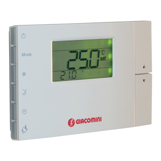
ermosTaTo ambienTe con sonda di TemperaTura e
K495L
umidiTà
R
K495L
oom theRmostat
Descrizione - Description
Il termostato ambiente con sonda di temperatura e umidità K495L permetto il
controllo degli impianti di riscaldamento e/o raffrescamento in combinazione
con il modulo di regolazione KPM30 o KPM31, al quale è collegato tramite
Bus. Il termostato K495L è stato sviluppato per essere installato a parete su
scatola a 3 posti standard italiano, oppure per essere applicato direttamente a
muro tramite tasselli. Attraverso la connessione Bus il termostato comunica al
modulo di regolazione i valori di temperatura e umidità relativa dell'ambiente
in cui è installato. La visualizzazione e l'impostazione della temperatura
ambiente misurata e desiderata può essere effettuata sia direttamente dal
display del termostato sia centralmente dal display del modulo di regolazione.
The room thermostat with temperature sensor and humidity K495L allow control
of heating and/or air-cooling in combination with the regulation unit KPM30 or
KPM31, to which it is connected by bus. The thermostat K495L was developed to
be installed on the wall of box 3 seater Italian standard, or to be applied directly to
the wall using wall anchors. By the bus connection the thermostat communicates
to the regulation unit the values of temperature and relative humidity of the room
in which it is installed. Viewing and setting the temperature measured and desired
can be done directly from the display of the thermostat or centrally by the display
of the control module.
Versioni e codici - Versions and product codes
Codice
Product code
K495LY002
Dati tecnici - Technical data
• Tensione di alimentazione (secondo EN60730-1): 24 Vac ±15 %, 50/60 Hz 70
mA 1,5 VA oppure 31 Vdc ±29 % 70 mA
• Classificazione secondo UL873:
- Ingresso alimentazione: 24 V ac, 50-60Hz, Class 2 - 25.5 - 36.25 V dc, Class 2
- Power consumption: max 1 watt
- Uscite: serial link RS485, Class 2
• Condizioni di funzionamento: 0÷50 °C; 10...85% U.R. non condensante
• Condizioni di immagazzinamento: -20÷70 °C; 0...85 % U.R. non condensante
• Inquinamento ambientale: normale
• Grado di Inquinamento: grado II
• Categoria di resistenza al calore e al fuoco: A
• Classe e struttura del software: A
• Grado di protezione contro gli agenti atmosferici: IP30
• Temperatura della ball pressure test sulle plastiche dell'involucro: 100 °C
• Classificazione secondo protezione contro scosse elettriche (EN60730-1): III,
da integrare in apparecchi di classe I o II
• Periodo sollecitazioni elettriche delle parti isolanti: lungo
• Dispositivo di comando previsto per essere fornito a: costruttori, installatori
e manutentori
hermoregulaTion
K495L
Alimentazione
Power supply
24 Vac
• Protezione contro i cortocircuiti: deve essere garantita dal costruttore
dell'apparecchiatura in cui il K495LY002 viene integrato o dall'installatore finale
• Immunità contro sovratensioni: categoria 1
• Sezione dei conduttori: da 0,5 a 1,5 mm
• Precisione della misura di temperatura: ±2 °C
• Precisione della misura di umidità: ±10 % U.R. (nei modelli dotati di sonda di
umidità opzionale) apparecchiature di classe I e II
• PTI dei materiali Isolanti: 250 V
• Periodo delle sollecitazioni elettriche delle parti isolanti: Lungo
• Grado di inquinamento ambientale: Normale
• Categoria di resistenza al calore ed al fuoco: Categoria D (per scatola e coperchio)
• Categoria di immunita' contro le sovratensioni: Categoria 2
• Power supply (according to EN60730-1): 24 Vac ±15 %, 50/60 Hz 70 mA 1.5 VA or
31 Vdc ± 29 % 70 mA
• Classification according to UL873:
- Power supply input: 24 V ac, 50-60Hz, Class 2 - 25.5 - 36.25 V dc, Class 2
- Power consumption, max 1 watt
- Outputs: serial link RS485, Class 2
• Operating conditions: 0÷50 °C; 10 to 85% rH non-condensing
• Storage conditions: -20÷70 °C; 0 to 85 % rH non-condensing
• Environmental pollution: normal
• Degree of pollution: degree II
• Category of resistance to heat and fire: A
• Software class and structure: A
• Index of protection: IP30
• Ball pressure test temperature on the plastic case: 100 °C
• Classification according to protection against electric shock (EN60730-1): III, to be
integrated into class I or II appliances
• Period of electrical stress across the insulating parts: long
• Control device designed to be supplied to: manufacturers, installers and
maintenance personne
• Protection against short-circuits: must be guaranteed by the manufacturer of the
appliance that the K495LY002 is integrated into or by the installer
• Immunity against voltage surges: category 1
• Cross-section of the wires: from 0.5 to 1.5 mm
• Precision of temperature measurement: ±2 °C
• Precision of humidity measurement: ±10 % rH. (in the models fitted with optional
humidity probe)
Installazione - Installation
Togliere l'alimentazione prima di intervenire sul dispositivo in fase di montaggio,
manutenzione e sostituzione. La distanza dei fori di montaggio è studiata per
poter fi ssare il dispositivo ad una scatola da incasso conforme alle normative CEI
C.431 - IEC 670. Se questa non è presente, usare i fori di montaggio sul guscio
come guida per la foratura sul muro e utilizzare poi il kit di viti e tasselli in dotazione.
I cavi di collegamento devono passare attraverso il foro presente nel centro del
guscio posteriore del dispositivo, e devono venire fi ssati ai morsetti posti sul
guscio stesso (Fig. 1.a). Per accedere ai morsetti di connessione è necessario
sganciare il guscio posteriore facendo leva sull'apposita linguetta. L'apertura e la
chiusura del dispositivo devono avvenire applicando un movimento "a cerniera"
facendo perno sul lato superiore dello strumento e sollevando quello inferiore
(vedi Fig. 1.b). In fase di chiusura fare attenzione che i perni sulla scheda si infi lino
nei corrispondenti morsetti, e che i cavi non ostacolino l' o perazione.
Disconnect the power supply before working on the K495LY002 during the assembly,
maintenance and replacement operations. The distances between the fastening
holes are designed so as to be able to fi t the device to a flush-mounting connection
box compliant with the CEI C.431 - IEC 670 standards. If this is not available, use the
fastening holes on the shell as a guide for drilling holes in the wall, and then use the
kit of screws and plugs supplied. The connection cables must pass through the hole
in the centre of the rear shell of the device, and must be connected to the terminals
located on the shell (Fig. 1.a). To access the connection terminals, remove the rear
shell by levering the tab. The device is opened and closed with a "hinge" movement,
pivoting the top part of the instrument and lifting the bottom part (see Fig. 1.b).
When closing, make sure that the pins on the board fi t into the corresponding
terminals, and that the cables do not hinder the procedure.
ISO
ISO
OHSAS
9001
14001
18001
0006/7
0032A/3
0064L/1
2
2
1
Advertisement

Subscribe to Our Youtube Channel
Related Manuals for Giacomini K495L


Summary of Contents for Giacomini K495L
- Page 1 KPM30 or • Protection against short-circuits: must be guaranteed by the manufacturer of the KPM31, to which it is connected by bus. The thermostat K495L was developed to appliance that the K495LY002 is integrated into or by the installer be installed on the wall of box 3 seater Italian standard, or to be applied directly to •...
- Page 2 0680ML Maggio 2014 - May 2014 ermosTaTo ambienTe con sonda di TemperaTura e K495L OHSAS umidiTà 9001 14001 18001 0006/7 0032A/3 0064L/1 K495L oom theRmostat Interfaccia seriale - Serial interface Nota. Note. Interfaccia seriale RS485 per la comunicazione con controllori, tramite Adottare precauzioni contro le scariche elettrostatiche nel maneggiare la scheda.
- Page 3 0680ML Maggio 2014 - May 2014 ermosTaTo ambienTe con sonda di TemperaTura e K495L OHSAS umidiTà 9001 14001 18001 0006/7 0032A/3 0064L/1 K495L oom theRmostat 6. Separare i cavi del dispositivo da cavi che alimentano carichi induttivi e di Impostazione dei parametri bus - Bus setting parameters potenza per evitare possibili disturbi elettromagnetici.
- Page 4 For additional information please check the website www.giacomini.com or contact the technical service: ' +39 0322 923372 6 +39 0322 923255 * consulenza.prodotti@giacomini.com This pamphlet is merely for information purposes. Giacomini S.p.A. retains the right to make modifications for technical or commercial reasons, without prior notice, to the items described in this pamphlet.
Need help?
Do you have a question about the K495L and is the answer not in the manual?
Questions and answers