Table of Contents
Advertisement
Quick Links
Advertisement
Table of Contents

Related Manuals for LEGRAND Middle Atlantic Forum


Summary of Contents for LEGRAND Middle Atlantic Forum
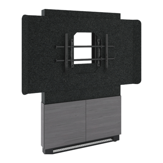
- Page 1 Instruction Sheet Forum ™ Collaboration Suite NOTE: Free standing and floor-to-wall models shown. THANK YOU Thank you for purchasing a Forum™ collaboration suite. Please read these instructions thoroughly before installing or assembling this product. 100-00066 Rev B...
-
Page 2: Table Of Contents
TABLE OF CONTENTS Important Safety Instructions......................3 - 4 Weight Ratings............................5 Supplied Components and Hardware....................5 - 7 Required Tools............................7 Introduction............................8 Removing the Front Panel from Your Display Stand................8 Attaching the Display Stand to Your Wall (Floor-To-Wall Models Only)........9 - 11 Installing and Configuring the 10" Lever Lock Plate.................11 Installing the Vertical Lever Lock Kit (if Purchased)................12 Using Top Small Device Storage and Bottom Rackmount Bays..........13 - 14 Re-Attaching the Front Panel to Your Display Stand................14... -
Page 3: Important Safety Instructions
IMPORTANT SAFETY INSTRUCTIONS • Read these instructions. • Heed all warnings. • Clean only with dry cloth. • Keep these instructions. • Follow all instructions. • Only use attachments/accessories specified by the manufacturer. DANGER HAZARDOUS VOLTAGE: The lightning flash with the arrowhead symbol, within an equilateral triangle is intended to alert the user to the presence of uninsulated dangerous voltage within the product’s enclosure that may be of sufficient magnitude to constitute a risk of electric shock to persons. - Page 4 INSTRUCTIONS IMPORTANTES SUR LA SÉCURITÉ • Lire ces instructions. • Respectez tous les avertissements. • Nettoyer uniquement avec un chiffon sec. • Conservez ces instructions. • Suivez toutes les instructions. • N'utilisez que des accessoires spécifiés par le fabricant. DANGER TENSION DANGEREUSE: Le symbole de la pointe de flèche, dans un triangle équilatéral, est destiné à alerter l'utilisateur sur la présence de tension dangereuse non isolée dans l'enceinte du produit qui peut être d'une ampleur suffisante pour constituer un risque d'électrocu- tion.
-
Page 5: Weight Ratings
Le poids total de l'équipement ne doit pas dépasser les quantités indiquées dans le tableau précédent. SUPPLIED COMPONENTS AND HARDWARE If any pieces are missing or damaged, please report it immediately to Technical Support at av.support@legrand.com or (866) 977-3901. CHIEF GRADE 5 TOGGLER KIT (Model Number: FCAT1) - Page 6 SUPPLIED COMPONENTS AND HARDWARE (CONTINUED) Shroud (4x) (4x) 5/16-18” 5/16-18” x 1¾” Flange Nut Flange Hex Head Bolt CHIEF FUSION FIXED DISPLAY MOUNT (4x) (4x) (4x) M4 x 12mm M4 x 20mm M4 x 25mm Interface Pan Head Screw Pan Head Screw Pan Head Screw Bracket (4x)
-
Page 7: Required Tools
(Model Number: MDCA3-WH) (Model Number: MDEA3-WH) NOTE: • To order more hardware, contact support at av.support@legrand.com or (866) 977-3901. • Additional hardware is included that may not be required for your installation. REQUIRED TOOLS WARNING: Use tools with caution and •... -
Page 8: Introduction
INTRODUCTION NOTE: • Please take the time to carefully unpack and inspect all of the products you ordered and save this instruction sheet for future use. • Maintenance and care information is provided in Care and Cleaning of Products (I-00788) and Unpacking and Handling Precautions (I-00787) for your convenience. -
Page 9: Attaching The Display Stand To Your Wall (Floor-To-Wall Models Only)
ATTACHING THE DISPLAY STAND TO YOUR WALL (FLOOR-TO-WALL MODELS ONLY) WARNING: This procedure requires at least one additional person. AVERTISSEMENT: Cette procédure nécessite au moins une personne supplémentaire. 1. Carefully team lift your display stand (A) and place it on its feet against your desired mounting wall. WARNING: The display stand must always bear its weight on its feet when wall mounted. - Page 10 ATTACHING THE DISPLAY STAND TO YOUR WALL (IF PURCHASED, CONTINUED) 5. The remaining sections of this topic show you how to attach the display stand to your specific wall type as follows: • “Attaching the Display Stand to a Wall With Steel Studs or Cinderblocks” on page 10. •...
-
Page 11: Installing And Configuring The 10" Lever Lock Plate
10” Lever Lock plate. For more information, contact support at Side Side av.support@legrand.com with clip without clip or (866) 977-3901. FIGURE G 1. Press the clip and lift the same side of the 10” plate from the display stand column. (FIGURE G) 2. -
Page 12: Installing The Vertical Lever Lock Kit (If Purchased)
INSTALLING THE VERTICAL LEVER LOCK KIT (IF PURCHASED) NOTE: • One 10” Lever Lock plate (F), bracket (G), (2x) screws (H), (6x) securing rivets (J), and (20x) washers (K) are provided with a Vertical Lever Lock kit, if purchased. • The 4 available mounting locations on the left and right columns of the display stand’s small device storage area are for vertical Lever Lock and are shaded in the figure for clarity. -
Page 13: Using Top Small Device Storage And Bottom Rackmount Bays
USING TOP SMALL DEVICE STORAGE AND BOTTOM RACKMOUNT BAYS 1. Load equipment into the top small device storage columns using “Installing and Configuring the 10” Lever Lock Plate” on page 11 and “Installing the Lever Lock Kit (If Purchased) on page 12 as needed. -
Page 14: Re-Attaching The Front Panel To Your Display Stand
USING TOP SMALL DEVICE STORAGE AND BOTTOM RACKMOUNT BAYS (CONTINUED) FLOOR-TO-WALL DISPLAY STANDS ONLY: • Access to the bottom rackmount bays is only available from the the front doors after re-installing the front panel and mounting your display. • The useable equipment depth of the bottom rackmount bays in a floor-to-wall display stand is 16”... -
Page 15: Attaching Interface Brackets To The Back Of Your Display
You may need to install any additional accessories you may have purchased such as compatible camera mounts, sound bars and other audio products (available from Legrand or other providers) before your display mount and display. Before proceeding, refer to the instructions provided with your accessory for the proper installation order. -
Page 16: Attaching The Shroud And Mount To Your Display Stand
ATTACHING THE SHROUD AND MOUNT TO YOUR DISPLAY STAND 1. Use your hand to loosely attach (2x) 5/16-18” x 1¾” flange hex head bolts NOTE: Select from top 10 hole pairs (shaded) for (L) to (2x) 5/16-18” flange nuts (M, approximately 2-3 thread rotations) preferred display height. -
Page 17: Hanging Your Display Onto The Mount
HANGING YOUR DISPLAY ONTO THE MOUNT WARNING: This procedure requires at least one additional person. AVERTISSEMENT: Cette procédure nécessite au moins une personne supplémentaire. 1. With at least one other person, carefully lift your display slightly above both top and bottom poles on the mount (I-E). - Page 18 ASSEMBLING YOUR TABLE (IF PURCHASED, CONTINUED) 2. Use hammer, screwdriver and/or awl to clear the knockouts on the same side/table leg assembly as shown. (FIGURE X) Clear NOTE: Adjust torque on power driver to lightest with Clear with setting and only increase as necessary. Hammer Screwdriver or Awl 3.
- Page 19 ASSEMBLING YOUR TABLE (IF PURCHASED, CONTINUED) Screw Locations on 3 Person Arc Table (16x Total) There are 3x screw There are 2x screw locations There are 4x screw locations on (one on each side) inside of leg locations on front and each arm.
-
Page 20: Understanding Cable Management
UNDERSTANDING CABLE MANAGEMENT • Carefully team lift the entire table assembly and place it right-side up. NOTE: • Table top (V) and panels removed for clarity. • The image shown of a 3 person angle table is provided as a cable management example of lines coming from the floor, up table leg assembly, through knockouts, tied to bridge lances, and out openings. -
Page 21: Installing Wiremold Modpower Options To Table (If Purchased)
INSTALLING WIREMOLD MODPOWER OPTIONS TO TABLE (IF PURCHASED) You may have purchased any number of optional Wiremold On Surface ModPower System Primary, Middle, or End units to provide power to your optional table(s). NOTE: • If purchased, a primary ModPower unit is required to run any additional middle and end units. •... -
Page 22: Warranty
Factory Distribution United States: New Jersey, California, and Illinois | Canada: Ontario | The Netherlands: Weert At Legrand AV Inc. we are always listening. Your comments are welcome. Legrand AV is an ISO 9001 and ISO 14001 Registered Company. Page 22...
Need help?
Do you have a question about the Middle Atlantic Forum and is the answer not in the manual?
Questions and answers