Table of Contents
Troubleshooting

Subscribe to Our Youtube Channel
Related Manuals for Bunn INFUSION SERIES ICB/TWIN


Summary of Contents for Bunn INFUSION SERIES ICB/TWIN
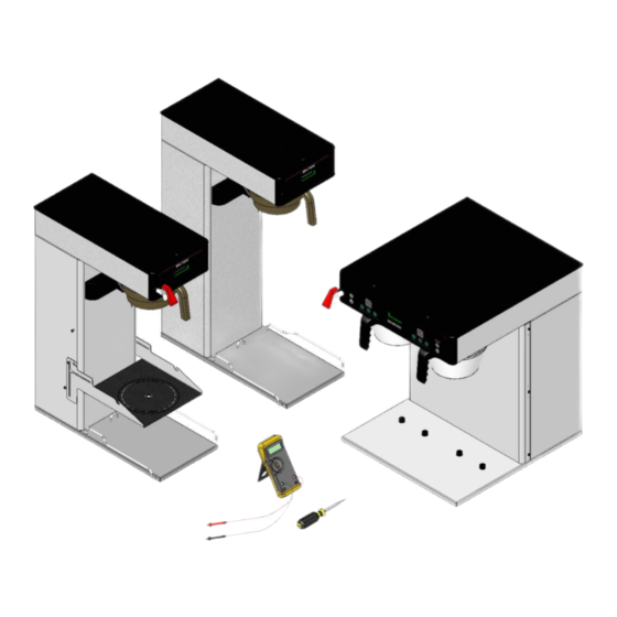
- Page 1 ITB/ITCB/HV ICB/TWIN ® Infusion Series SERVICE & REPAIR MANUAL BUNN-O-MATIC CORPORATION POST OFFICE BOX 3227 SPRINGFIELD, ILLINOIS 62708-3227 PHONE: (217) 529-6601 FAX: (217) 529-6644 42461.0000B 08/11 ©2010 Bunn-O-Matic Corporation...
-
Page 2: Warranty
SOLE OPTION AS SPECIFIED HEREIN, TO REPAIR, REPLACEMENT OR REFUND. In no event shall BUNN be liable for any other damage or loss, including, but not limited to, lost profi ts, lost sales, loss of use of equipment, claims of Buyer’s customers, cost of capital, cost of down time, cost of substitute equipment, facilities or services, or any other special, incidental or consequential damages. -
Page 3: Table Of Contents
This equipment will brew a half-gallon batch of coffee into an awaiting dispenser. It can be easily confi gured for 120V 15 amp, 120/208V 20 amp or 120/240V 20 amp. The brewer may have a hot water faucet for allied beverage use. It is only for indoor use on a sturdy counter or shelf. Warranty ...2 Contents ...3 Troubleshooting ...4... -
Page 4: Troubleshooting
A troubleshooting guide is provided to suggest probable causes and remedies for the most likely problems encountered. If the problem remains after exhausting the troubleshooting steps, contact the Bunn-O-Matic Technical Service Department. • Inspection, testing, and repair of electrical equipment should be performed only by qualifi ed service person- nel. - Page 5 TROUBLESHOOTING (cont.) REFILL CIRCUIT PROBLEM Will not refi ll Refi ll does not shut off Power "ON" Refi ll does not shut off Power "OFF" PROBABLE CAUSE 1. Power off to brewer 2. Water shut off 3. Error Message 4.ON/OFF Switch (If equipped) 5.
- Page 6 TROUBLESHOOTING (cont.) HEATING CIRCUIT PROBLEM Water does not heat to proper temperature IMPORTANT: Make sure no tem- perature tests are taken before the display reads ready. Tank tem- perature must be stabilized before readings are taken. Spitting or excessive steaming (cont.) Brewer is making unusual noises PROBABLE CAUSE...
-
Page 7: Troubleshooting
TROUBLESHOOTING (cont.) BREWING CIRCUIT PROBLEM Brew cycle will not start Consistently low beverage level in the dispenser or beverage overfl ows dispenser PROBABLE CAUSE 1. Display's error message 2. No water 3. No power or incorrect voltage to the brewer 4. - Page 8 195°F (91°C). Adjust the temperature setting to increase the water temperature. Refer to Initial Set-up instructions. BUNN® paper fi lters must be used for proper extraction. A fi ne drip or grind must be used for proper extraction.
- Page 9 DIAGNOSTICS MESSAGE Temperature Too Low Heating Time Too Long Fill Time Too Long Temp Sensor Out Of Range, Check For Bad Connections Temp Sensor Out Of Range, Check Wire For Shorts PROBABLE CAUSE 1. Water temperature in the tank does not meet the ready tempera- ture.
-
Page 10: Access
COMPONENT ACCESS This section provides procedures for testing and replacing various major components used in this brewer should service become necessary. Refer to Troubleshooting for assistance in determining the cause of any problem. WARNING - Inspection, testing, and repair of electri- cal equipment should be performed only by qualifi... -
Page 11: Control Board
CONTROL BOARD FIG. 11-1 CONTROL BOARD Location: The Control Board is located inside the top cover behind the front face plate. Test Procedures: The test procedures for the control board will vary depending upon the problems experienced by the brewer. Refer to the Troubleshooting section which is divided into three sections, Refi... - Page 12 CONTROL BOARD-ICB TWIN/ITCB DV HV/ITCB TWIN HV TRIAC MAP Triac: Load Component: TH1/MOV4/BR2 Left Funnel Lock TH2/MOV1 Refi ll solenoid TH3/MOV3/BR3 Right Funnel Lock TH4B/MOV2 Tank Heaters TH5/MOV5 Left Brew Solenoid TH6/MOV7 Right Brew Solenoid TH7/MOV8 Left Bypass Solenoid TH8/MOV6 Right Bypass Solenoid FIG.
- Page 13 CONTROL BOARD-ICB/ITCB TRIAC MAP Triac: Load Component: TH2/MOV1/BR2 (Optional) Funnel Lock (ICB) TH4B/MOV2 Refi ll solenoid TH6/MOV4 Brew Solenoid TH7/MOV3 Tank Heater(s) TH9/MOV5 Dilution or Bypass Solenoid FIG. 13-1 TRIAC MAP Connector: J17-13/J17-14 J17-5 J17-3 Relay Terminal J17-1 42461 081310...
- Page 14 CONTROL BOARD-ITB TRIAC MAP Triac: Load Component: TH1/MOV3 Main or Left Dilution TH2/MOV1 Refi ll solenoid TH3/MOV2 Brew Solenoid TH4/MOV4 Right Dilution TH6/MOV6 Sweetner TH7/MOV7 Tank Heater FIG. 14-1 TRIAC MAP Connector: J10-1 J10-2 J10-3 J10-4 J10-5 TR1/TR6 42461 081310...
-
Page 15: Membrane Switch
MEMBRANE SWITCH FIG. 15-1 MEMBRANE SWITCH Location: The Membrane Switch is located on the front face plate. Test Procedures: There are two methods for testing the membrane switch. The easiest method is to use the built in test mode. Refer to the Programing Section for Service Tools/Test Switches. -
Page 16: Brew Valves (Early)
BREW VALVE (EARLY MODELS) AND BYPASS VALVE ON ALL ICB's FIG. 16-1 EARLY BREW VALVE Location: The brew valve is located inside the top cover behind the front face plate. Test Procedures: 1. Refer to the Programing Section for Service Tools/ Test Outputs/Brew Valve. - Page 17 BREW VALVE (LATE MODELS) FIG. 17-1 LATE MODEL BREW VALVE Location: The brew valve is located inside the top cover behind the front face plate. Test Procedures: 1. Refer to the Programing Section for Service Tools/ Test Outputs/Brew Valve. 2. Be sure brew funnel & server are in place before activating valve.
-
Page 18: Refi Ll Valves
8. Install access panels and covers and refer to Initial Set-up for refi ll and operation. Disassembly: Bunn does not offer repair/rebuild kits for the refi ll valves, but some disassembly may be accomplished on the early style valves in the event they may need to be cleaned out. - Page 19 REFILL VALVES EARLY ICB CURRENT ICB & & ITB Flow control used SCREEN on dual dilution STRAINER models only EARLY ITCB CURRENT ITCB & ITB-DD SCREEN STRAINER 42461 081310...
-
Page 20: Tank Heaters
TANK HEATERS FIG. 20-1 ICB TWIN TANK HEATERS Location: The tank heaters are located inside the tank and secured to the tank bottom. Test Procedures: 1. With a voltmeter, check voltage across the white wire (120V Models) or red wire (120/208-240V Models) from the terminal block and black wire from the control board. -
Page 21: Limit Thermostat
LIMIT THERMOSTAT FIG. 21-1 LIMIT THERMOSTAT Location: The limit thermostat is located on the tank lid (on the front of the tank on twins). FIG. 21-2 LIMIT THERMOSTATS Test Procedures: 1. Disconnect the brewer from the power source and allow to cool. 2. -
Page 22: Temperature Probe
TEMPERATURE PROBE FIG. 22-1 TEMPERATURE PROBE Location: The temperature probe is inserted through the tank lid assembly. Test Procedures: 1. Disconnect the brewer from the power source. 2. With a DC voltmeter, check voltage across the two wires at J13 (J3 on ITB) on control board (black probe to black wire, red probe to white wire refer to FIG 19-2). - Page 23 TEMPERATURE PROBE Removal and Replacement: 1. Disconnect the brewer from the power source. 2. Disconnect the two pin connector from J9 on control board. 3. Pull temperature probe out of it's grommet. 4. Install in reverse order. Calibration: 1. Remove silicon vent fi tting from tank lid. 2.
-
Page 24: Voltage Selector Switch
VOLTAGE SELECTOR SWITCH FIG. 24-1 VOLTAGE SELECTOR SWITCH Location: The voltage selector switch is located on the component mounting bracket on the base plate. Test Procedure: 1. Disconnect the brewer from the power source. 2. Disconnect the wires from the selector switch. With the selector switch in the 120V position, check for continuity between the two right terminals of the switch. -
Page 25: Power Switch
POWER SWITCH FIG. 25-1 POWER SWITCH (ICB SHOWN) Location: The power switch is located on the lower right side of the trunk (ICB) or lower rear panel (ITCB). Test Procedure: 1. Disconnect the brewer from the power source. 2. Disconnect the wires from the power switch. With the switch in the ON position, check for continuity between the upper and lower terminals on each side of the switch. -
Page 26: On/Off Switch
TANK HEATER WHI/VIO-14 1680W 1800W DILUTION WHI/VIO DISPENSE REFILL WHI/BLU PROG L PROG R FULL HALF ON/OFF FULL ON/OFF 120V AC 2 WIRE 120/208V AC 3 WIRE 120/240V AC 3 WIRE SINGLE PHASE 36460.0000D 02/07 ©2004 BUNN-O-MATIC CORPORATION RED-14 42461 081310... - Page 27 GRN/YEL FILTER TANK HEATER BLK-14 RED-14 3500W DILUTION WHI/VIO DISPENSE WHI/GRN REFILL WHI/BLU PROG L PROG R FULL HALF ON/OFF FULL ON/OFF 200V AC 2 WIRE 230V AC 2 WIRE SINGLE PHASE 36460.0001C 08/09 ©2004 BUNN-O-MATIC CORPORATION RED-14 42461 081310...
-
Page 28: Schematic Wiring Diagram
OPTIONAL BRN/WHI SWEETENER BRN/WHI DILUTION WHI/VIO DISPENSE REFILL WHI/BLU PROG L PROG R FULL HALF ON/OFF FULL ON/OFF 120V AC 2 WIRE 120/208V AC 3 WIRE 120/240V AC 3 WIRE SINGLE PHASE 36460.0003A 06/08 ©2008 BUNN-O-MATIC CORPORATION RED-14 42461 081310... - Page 29 DISPENSE REFILL WHI/BLU SWEETENER BRN/WHI LOW PRODUCT DETECT SWITCH PROG L PROG R FULL HALF ON/OFF FULL ON/OFF 120V AC 2 WIRE 120/208V AC 3 WIRE 120/240V AC 3 WIRE SINGLE PHASE 36460.0004A 10/08 ©2008 BUNN-O-MATIC CORPORATION RED-14 42461 081310...
- Page 30 2268W BYPASS WHI/RED DISPENSE REFILL WHI/BLU FUNNEL LOCK (Optional) PROG L PROG R FULL HALF ON/OFF FULL ON/OFF 120V AC 2 WIRE 120/208V AC 3 WIRE 120/240V AC 3 WIRE SINGLE PHASE 37299.0000B 02/07 ©2004 BUNN-O-MATIC CORPORATION RED-14 42461 081310...
- Page 31 J16-1 MEMORY BOARD J16-5 (Early Models only) 120/208 OR 120/240 STATIC SHIELD VOLTS AC 3 WIRE + GND SINGLE PHASE 37299.0001C 02/07 ©2005 BUNN-O-MATIC CORPORATION MAIN ON/OFF SWITCH (Late Models only) BLK-18 BLK-14 LIMIT THERMOSTAT TANK HEATER BLU-14 BLU-14 RED-14...
- Page 32 FILTER TANK HEATER 3500W BYPASS WHI/RED DISPENSE WHI/GRN REFILL WHI/BLU FUNNEL LOCK (Optional) PROG L PROG R FULL HALF ON/OFF FULL ON/OFF 200V AC 2 WIRE 230V AC 2 WIRE SINGLE PHASE 37299.0002B 08/09 ©2005 BUNN-O-MATIC CORPORATION RED-14 42461 081310...
- Page 33 PROBE CONTROL PANEL ASSY LEFT ON/OFF LEFT FULL LEFT HALF RIGHT ON/OFF RIGHT FULL RIGHT HALF STATIC SHIELD 37299.0004A 12/08 ©2008 BUNN-O-MATIC CORPORATION L1 L2 TERM BLOCK FILTER BLK-18 BLK-14 RED-14 RED-14 LEFT BYPASS LEFT DISPENSE REFILL RIGHT BYPASS RIGHT...
- Page 34 RIGHT DILUTION (DUAL DILUTION MODELS ONLY) OPTIONAL SWEETENER OPTIONAL LOW PRODUCT DETECT SWITCH BREW PROG L BREW PROG R HALF FULL BREW HALF ON/OFF FULL ON/OFF 120V AC 2 WIRE + GROUND SINGLE PHASE 42377.0000B 12/09 ©2009 BUNN-O-MATIC CORPORATION 42461 081310...
- Page 35 HALF ON/OFF FULL ON/OFF STATIC SHIELD 120V AC 2 WIRE 120/208V AC 3 WIRE 120/240V AC 3 WIRE SINGLE PHASE 43828.0000A 11/10 ©2010 BUNN-O-MATIC CORPORATION GRN/YEL Chassis Ground MAIN ON/OFF SWITCH BLK-18 BLK-14 TANK HEATER RED-14 2268W COOLING FAN REFILL...
- Page 36 THERMISTOR J3-8 J2-1 J2-5 J2-10 J2-15 J2-20 J2-22 120/208 OR 120/240 VOLTS AC 3 WIRE + GND SINGLE PHASE 44145.0000A 01/11 ©2011 BUNN-O-MATIC CORPORATION MAIN ON/OFF SWITCH Earth Ground Chassis Ground BLK-18 BLK-14 LIMIT THERMOSTAT TANK HEATER BLU-14 BLU-14 RED-14...
Need help?
Do you have a question about the INFUSION SERIES ICB/TWIN and is the answer not in the manual?
Questions and answers