Bunn CDBC Operating & Service Manual
Bunn cdbc: service manual
Hide thumbs
Also See for CDBC:
- Operating & service manual (36 pages) ,
- Operating & service manual (32 pages) ,
- Operating & service manual (35 pages)
Table of Contents
Advertisement
OPERATING & SERVICE MANUAL
29319.0000D 09/03 ©1999 Bunn-O-Matic Corporation
N
ER
IO
NT
U T
CA
C A
D DE
AR
DI SC
!
IF :
D
AC
KE
D
. CR
TC
HE
PT
Y
RA
D DR
Y
EM
. SC
EN
AM
E
ILE
WH
FL
IC
. BO
ED
HI GH
TR
. HE
AT
ON
D EL
EC
RY
ED
SE
JU
TS
. US
PO
S IN
ION
EN
EX
TS
OR
AT
NT
. OR
Y RI
SK
EN
CO
RP
CO
EM
TIC
EL
T
M PL
EL
-O-
MA
NN
E HO
CO
5 BU
NN
FU
AR
E TO
198
IL UR
FA
: 658
PN
N
ER
IO
NT
U T
CA
DE
C A
D
SC
AR
DI
!
IF :
D
KE
D
. CR
AC
HE
Y
RA
TC
Y
PT
. SC
D
DR
EN
EM
E
ILE
WH
FL
AM
IC
. BO
ED
HI GH
TR
AT
EL
EC
. HE
ON
D
RY
. US
ED
PO
SE
S IN
JU
ION
TS
EX
AT
NT
EN
. OR
Y RI
SK
EN
TS
OR
RP
CO
EM
TIC
CO
T
M PL
EL
MA
NN
EL
E HO
NN
-O-
FU
CO
5 BU
AR
E TO
198
IL UR
FA
: 658
PN
BUNN-O-MATIC CORPORATION
POST OFFICE BOX 3227
SPRINGFIELD, ILLINOIS 62708-3227
PHONE: (217) 529-6601 FAX: (217) 529-6644
CEZ
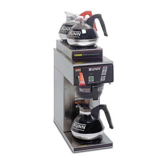
CDBC
TWIN
P
TO
T
AR
ST
W ER
LO
O N/
P
TO
N
NT
ER
IO
CA
T
U T
DE
ST
AR
C A
D
AR
SC
W ER
!
DI
IF :
O N/
LO
KE
D
AC
HE
D
. CR
TC
Y
PT
Y
RA
D DR
EM
E
. SC
EN
AM
. BO
ILE
WH
FL
IC
AT
ED
HI GH
EC
TR
. HE
ON
D
EL
RY
ED
SE
JU
TS
. US
PO
S IN
AT
ION
EN
EX
SK
TS
OR
NT
. OR
Y RI
EN
CO
RP
CO
M PL
EL
EM
TIC
EL
T
-O-
MA
NN
E HO
CO
5 BU
NN
FU
AR
E TO
198
IL UR
FA
: 658
PN
www.bunnomatic.com
Advertisement
Chapters
Table of Contents

Related Manuals for Bunn CDBC


Summary of Contents for Bunn CDBC
- Page 1 OPERATING & SERVICE MANUAL BUNN-O-MATIC CORPORATION 29319.0000D 09/03 ©1999 Bunn-O-Matic Corporation D DE DI SC IF : . CR D DR . SC . BO HI GH . HE D EL . US S IN . OR Y RI M PL...
-
Page 2: Table Of Contents
REPAIR, REPLACEMENT OR REFUND. In no event shall BUNN be liable for any other damage or loss, including, but not limited to, lost profits, lost sales, loss of use of equipment, claims of Buyer’s customers, cost of capital, cost of down time, cost of substitute equipment, facilities or services, or any other special, incidental or consequential damages. -
Page 3: User Notices
DO NOT DEFORM PLUG OR CORD. FOLLOW NATIONAL AND LOCAL ELECTRICAL CODES. KEEP COMBUSTIBLES AWAY. FAILURE TO COMPLY RISKS EQUIPMENT DAMAGE, FIRE OR SHOCK HAZARD. READ THE ENTIRE OPERATING MANUAL BEFORE USING THIS PRODUCT 00986.0000E 5/98 ©1994 Bunn-O-Matic Corporation Page 3 29319 041599... -
Page 4: Electrical & Plumbing Requirements
These brewers must be connected to a cold water system with operating pressure between 5 and 90 psi (34.5 and 620 kPa) for CDBC models and 20 and 90 psi (138 and 620 kPa) for CEZ models from a line. A shut-off valve should be installed in the line before the brewer. Install a regulator in the line when pressure is greater than 90 psi (620 kPa) to reduce it to 50 psi (345 kPa). -
Page 5: Operating Controls
Placing any additional warmer switch in the "ON" upper position supplies power to the associated warmer. READY INDICATOR This indicator glows when the preselected brew water temperature has been achieved. Model CDBC TWIN ON/OFF SWITCH Pressing the "ON/OFF" switch (indicator glowing) supplies power to the brew station warmer, enables the brew circuit, and energizes the tank refill circuit. -
Page 6: Initial Set-Up, Coffee Brewing, & Cleaning
Place a small vessel beneath the faucet and open the faucet handle. Release it when you hear water once again flowing into the tank. Model CDBC – With the "ON/OFF" switch still in the "ON" position (indicator glowing), momentarily press and release the "BREW" switch. -
Page 7: Cez Adjustments & Optional Settings
CEZ ADJUSTMENTS & OPTIONAL SETTINGS IMPORTANT: The tank must be full and refill solenoid shut off prior to making these adjustments. Sprayhead must be installed while making these adjustments. TRM1 COUNTER READY LOCK UNLOCK (Brew Lockout Enabled) TEMPERATURE TEMPERATURE TEMPERATURE 205°... -
Page 8: Cdbc Adjustments & Optional Settings
CDBC ADJUSTMENTS & OPTIONAL SETTINGS NOTE: The following adjustments must be performed for each Brew Station. Setting Brew Temperature The brewer is factory set to brew at 200°F(95°C). To change this setting, press and hold the "HIDDEN" switch beneath the "®". The word "TEMP" above the "ON/OFF" switch will glow to correspond with the temporary function change of this switch. -
Page 9: Adjusting Brew Volumes
"BREW" switch and allow the cycle to finish. WATER SENSING THRESHOLD ADJUSTMENT PROCEDURE (CDBC TWIN & CDBCF TWIN) 1. Make sure the tank is full of water to be used for calibration. The water must be in contact with the refill probe. -
Page 10: Cdbc Pulse Brew Setup Procedure
PULSE BREW SETUP PROCEDURE (CDBC TWIN & CDBCF TWIN) The pulse brew parameters (initial fill time, off times, and remaining on times) are entered using the following set- by-example process. 1. First set the brew volume using the standard procedure in Brew Volume Setup. -
Page 11: Troubleshooting
Make sure before servicing brewer that voltage is present at control board. On CDBC TWIN models, press any warmer switch or observe if any indicator lights are glowing on the control panel. If so, proceed with testing. If not, check for voltage across pins 1 & 2 of the ten pin J1 connector (black and white wires). - Page 12 2. Water shut off (CDBC & CEZ) 3. Display flashing (CDBC) or ready light flashing (CEZ) 4. ON/OFF Switch (CDBC & CEZ) 5. Lime build up on Probe (CDBC & CEZ) 6. Refill Valve or Control Board (CDBC & CEZ) 7.
- Page 13 (CDBC) 2b. Water Level Probe Sensing Sys- tem (CEZ) 3. Refill valve or control board (CDBC & CEZ) 4. Water is too conductive for proper operation when using the factory setting of sensing threshold. 1. Refill valve or control board (CDBC &...
- Page 14 "ON". Tank tempera- ture must be stabilized before read- ings are taken. PROBABLE CAUSE 1. Display flashing (CDBC) or ready light flashing (CEZ) 2. Water not touching tempera- ture probe 3a. Dry Plug In Probe Sensing System (CDBC) 3b.
- Page 15 Spitting or excessive steaming PROBABLE CAUSE 4a. Temperature Probe (CDBC) 4b. Temperature Probe (CEZ) 5. Limit Thermostat (CDBC & CEZ) 6. Tank Heater (CDBC & CEZ) 1. Lime build up on temperature probe, tank or tank heater Page 15...
- Page 16 Spitting or excessive steaming (cont.) Brewer is making unusual noises PROBABLE CAUSE 2a. Temperature Probe (CDBC) 2b. Temperature Probe (CEZ) 3. Control Board (CDBC & CEZ) 1. Plumbing lines 2. Water supply 3. Lime build up Page 16 REMEDY A) Remove the probe from the grommet and submerge in a water bath of approximately 70°F(21°C).
- Page 17 TROUBLESHOOTING (cont.) BREWING CIRCUIT PROBLEM Brew cycle will not start PROBABLE CAUSE 1. Display flashing (CDBC) or ready light flashing (CEZ) 2. No water 3. No power or incorrect voltage to the brewer 4. ON/OFF switch not in the "ON"...
- Page 18 PROBABLE CAUSE 8. Control board or dispense valve (CDBC & CEZ) 1. Brew volume (CDBC & CEZ) 2. Lime build up 3. Dispense Valve Page 18 REMEDY If the start switch (CEZ) or switch panel (CDBC) is operating prop- erly, proceed as follows.
- Page 19 BUNN paper filters must be used for proper extraction. A fine or drip grind must be used for proper extraction. The BUNN ® paper filter must be centered in the funnel and the bed of grounds leveled by shaking gen- tly.
- Page 20 There should be six sepa- rate streams of water coming out of the sprayhead. The BUNN ® paper filter must be centered in the funnel and the bed of grounds leveled by shaking gen- tly.
-
Page 21: Diagnostics
Intermittent flashing of the READY indicator (Model CEZ) or the bank of temperature indicators (Model CDBC) indicates that a fault exists. Count the number of flashes between pauses and use this chart as a guide to investigating the fault. FLASHES CAUSE... -
Page 22: Service
Each warmer assembly is attached with three #4- 40 screws. Contents Control Board - CDBC ... 23 Control Board - CEZ ... 24 Switch Panel - CDBC ... 25 ON/OFF Switches - CEZ ... 26 BREW Switch (Start) - CEZ ... 27 Dispense Valve ... -
Page 23: Control Board - Cdbc
7. Connect the 10-pin connector and the 4-pin con- nector from the main wiring harness. 8. Connect the blue wire and black wire to the relay on the control board. 9. Refer to CDBC Adjustments and Optional Settings to program the new control board. Page 23 29319 091203... -
Page 24: Control Board - Cez
SERVICE (cont.) PC CONTROL BOARD - Model CEZ /L O FIG. 3 CONTROL BOARDS - CEZ Location: The Control Boards are located inside the trunk behind the front access panel. Test Procedures: The test procedures for the control boards will vary depending upon the problems experienced by the brewer. -
Page 25: Switch Panel - Cdbc
D EL R EX IN J R IS IL U : 65 FIG. 4 SWITCH PANELS - CDBC Location: The Switch Panels are located on the front of the hood. Test Procedures: The test procedures for the switch panels and the control boards will vary depending upon the problems experienced by the brewer. -
Page 26: Wiring Diagrams
SERVICE (cont.) ON/OFF SWITCHES - Model CEZ ID E T -S D IS /L O IF : O IL H IG R IS IL U : 65 FIG. 5 ON/OFF SWITCHES Location: The ON/OFF switches are located on the front of the hood. -
Page 27: Brew Switch (Start) - Cez
SERVICE (cont.) BREW SWITCH (Start) - Model CEZ /L O ID E T -S D IS /L O IF : O IL H IG IN J R IS IL U : 65 FIG. 7 BREW SWITCHES Location: The BREW switches are located on the front of the hood. -
Page 28: Dispense Valve
SERVICE (cont.) DISPENSE VALVE D IS IF : O IL R IS IL U : 65 FIG. 9 DISPENSE VALVES Location: The dispense valves are located inside the top cover, attached to the sprayhead panels. Test Procedures: 1. Disconnect the brewer from the power source. 2. -
Page 29: Limit Thermostat
SERVICE (cont.) LIMIT THERMOSTAT ID E T -S /L O D IS IF : O IL R IS IL U : 65 FIG. 11 LIMIT THERMOSTATS Location: The limit thermostats are located inside the front access panel on the front side of the tanks. Test Procedures: 1. -
Page 30: Tank Heaters
SERVICE (cont.) TANK HEATERS FIG. 13 TANK HEATER Location: The tank heaters are located inside the tanks and secured to the tank bottoms. Test Procedures: 1. Disconnect the brewer from the power supply. 2. With a voltmeter, check the voltage across the red wire from the terminal block and the black wire from the control board. - Page 31 SERVICE (cont.) TANK HEATERS (Cont.) 17. Install tank assembly onto mounting brackets and secure in place with four #8-32 nuts. 18. Install tank lid and secure in place with eight #8-32 nuts. 19. Connect the two white wires of the tank warmer blanket.
-
Page 32: Refill Valve
SERVICE (cont.) REFILL VALVE FIG. 15 REFILL VALVE Location: The refill valves are located inside the trunk on the lower center part of the component brackets. Test Procedures: 1. Disconnect the brewer from the power source. 2. Disconnect the white and white/blue wires from the refill valve. -
Page 33: Warmer Elements
SERVICE (cont.) WARMER ELEMENT(S) IF : . CR . SC . BO . HE . US . OR S IN Y RI M PL E HO 5 BU E TO IL UR : 658 FIG. 15 WARMER ELEMENTS Location: The warmer elements are located under the warmer plates. -
Page 34: Wiring Diagrams
Page 34 29319 091203... - Page 35 Page 35 29319 091203...
- Page 36 Page 36 29319 091203...
Need help?
Do you have a question about the CDBC and is the answer not in the manual?
Questions and answers