Table of Contents
Advertisement
Advertisement
Table of Contents

Related Manuals for Hinowa LightLift 15.70 3S


Summary of Contents for Hinowa LightLift 15.70 3S
- Page 1 TECHNICAL COURSE BOOKLET LightLift 15.70 3S PERFORMANCE TTLL1570021702...
-
Page 2: Table Of Contents
INDEX INTRODUCTION ..........................6 PARTS DENOMINATION ......................6 SERIAL NUMBER LOCATION ..................... 8 LL15.70 DATA ..........................9 TECHINCAL SPECIFICATIONS ....................9 LL15.70 DIMENSIONS ....................... 11 LL15.70 WORKING AREA - 230 KG UNRESTRICTED CAPACITY ....... 13 MACHINE OPERATIONAL INTRODUCTION ................ 14 MACHINE IGNITION ........................ - Page 3 ENGINE EMERGENCY START PROCEDURE ................ 44 7.4.1 GASOLINE – HONDA iGX390 EMERGENCY START ............. 45 7.4.2 DIESEL - HATZ 1B40 EMERGENCY START ..............46 HYDRAULIC SYSTEM ........................47 MAIN COMPONENTS IDENTIFICATION AND LOCATION ..........47 HYDRAULIC DIAGRAM ....................... 49 8.2.1 HYDRAULIC DIAGRAM INDEX ....................
- Page 4 DIAGNOSE AND SETTINGS ..................... 76 10.1 DIAGNOSE AND SETTINGS BY REMOTE CONTROL ........... 76 10.1.1 DISPLAY ICONS ........................76 10.1.2 INPUT ............................78 10.1.3 LANGUAGE ..........................85 10.1.4 ERRORS ..........................86 10.1.5 RAMPS ............................. 87 10.1.6 CURRENTS ..........................87 10.1.7 WORKING HOURS .......................
- Page 5 10.1.9.8.6.4 AD TEST ........................93 10.1.9.8.6.5 AS TEST ........................93 10.1.9.8.6.6 SKYGUARD ......................... 94 10.1.9.8.7 OPTIONAL (PAGE 3) ....................94 10.1.9.8.7.1 CHG SET ........................94 10.1.9.8.7.2 INV SET ........................94 10.2 REMOTE CONTROL CONNECTION ON THE GROUND CONNECTOR ..... 95 POWER SYSTEM ...........................
-
Page 6: Introduction
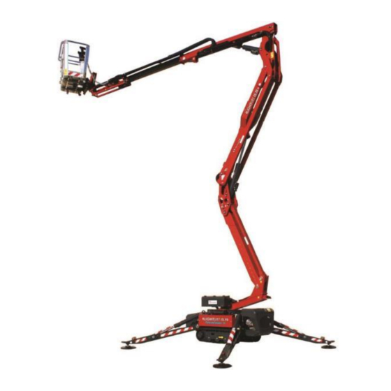
INTRODUCTION This booklet describes the technical and safety features, the electrical system and the hydraulic system of the Hinowa LightLift 15.70 3S Performance. It does not include how to operate the machine, for this purpose refer to the Operation and Maintenance Manual. - Page 7 specific seat in the basket, anyway there are others options illustrated and described later. BASKET CYLINDER TELESCOPE THIRD BOOM THIRD BOOM CYLINDER SECOND BOOM FIRST AND SECOND BOOMS CYLINDER FIRST BOOM TURRET SLEW RING...
-
Page 8: Serial Number Location
SERIAL NUMBER LOCATION To identify the machine a serial number plate is affixed on to the frame of the machine. The following illustrations showing its location. SERIAL NUMBER PLATE LOCATION The machine serial number is also printed on the frame. -
Page 9: Ll15.70 Data
LL15.70 DATA TECHINCAL SPECIFICATIONS MACHINE ENGINE TECHNICAL Platform capacity 230 Kg Max height (basket floor level) 13,30 m Max working height 15,40 m Up & Over height 7,0 m Max working horizontal extension 6,60 m Basket dimensions (standard two persons basket) 1335x690xH1100mm Length with basket installed 4020 mm... - Page 10 Battery 60Ah - 680A - 12V Gasoline engine alternator current 10 A at 3600rpm Diesel engine alternator current 14÷15 A at 3600rpm Electric motor rated voltage 230V - 110V - 120V Electric motor frequency 50Hz - 50Hz - 60Hz Electric motor rated powers 2,2 Kw - 2,2 Kw - 1,2 Kw DATA DIESEL ENGINE TECHNICAL Brand/model...
-
Page 11: Ll15.70 Dimensions
LL15.70 DIMENSIONS MACHINE IS SHOWN HERE BELOW WITH THE 2 PERSONS BASKET, DIMENSIONS REPORTED IN THIS DRAWING ARE NOMINAL, THE REAL VALUE OF EACH DIMENSION CAN BE INFLUENCED BY COMPONETS MANUFACTURE TOLLERANCES AND ELASTIC DEFORMATIONS DUE TO THE FORCES EFFECTS. -
Page 13: Ll15.70 Working Area - 230 Kg Unrestricted Capacity
LL15.70 WORKING AREA - 230 KG UNRESTRICTED CAPACITY... -
Page 14: Machine Operational Introduction
MACHINE OPERATIONAL INTRODUCTION The LL15.70 aerial platform is divided into two main parts: Ground part (or undercarriage part) Aerial part Driving or using the outriggers we are using the ground part. Moving the booms or the turret rotation we are using the aerial part. All of those movements are carried out by the remote control. - Page 15 Operator has to press the remote control “ENGINE” button to start it, or he has to press the remote control “ELECTRIC MOTOR” button to switch it ON. EMERGENCY STOP BUTTONS ENGINE ELECTRIC BUTTON MOTOR BUTTON While engine or electric motor are running, the same relevant “ENGINE” or “ELECTRIC MOTOR”...
-
Page 16: Stop Buttons
STOP BUTTONS Machine is equipped with two emergency stop buttons, one on the remote control that could be always use by the operator holding the remote control, and another one outside the ground control box. Pressing an emergency stop button the engine or the electric motor will be switched OFF, avoiding any machine movement. - Page 17 THIRD BASKET GRAVITY TURRET BOOM ROTATION EMERGENCY ROTATION 1-2 ARMS DESCENT RIGHT TRACK LEFT TRACK TELESCOPE OUTRIGGERS SERVICE AUTOMATIC MENU RETRACTION SELECTOR DISPLAY BASKET LEVELING SINGLE OUTRIGGER MOVEMENT ENGINE SPEED SELECTOR SELECTOR AUTO- ELECTRIC STABILIZATION MOTOR UNDERCARRIAGE (START-STOP) CLOSING GROUND ASSENT ENGINE ENGINE WARM UP...
-
Page 18: Ground Part Movements
GROUND PART MOVEMENTS TRACKS MOVEMENTS ERROR To allow tracks movements none of the outriggers have to be touching the ground, doesn’t matter if completely lifted up or just lifted, doesn’t matter if opened or in stowed position. When machine is not closed and aligned, if operator try to move an outrigger display will remind that machine need to be closed and aligned by the error message aside. - Page 19 If in the basket is still on its support, it will be not possible to move the jib or to drive the tracks with jib already opened. In those cases the error message “UNLOAD THE BASKET” will be displayed. “UNLOAD THE BASKET” ICON To reach the total length of 3400 mm the basket must be unloaded and its support must be lifted acting on its pin, as indicated below.
- Page 20 When basket is installed back on its support the two pins stoppers must be completely screwed. NOTE: In case of need, basket pin must be screwed at 50Nm. 50Nm If pedal option is active and the remote control is on its basket support the operator standing into the basket has to press the pedal while moving the tracks.
-
Page 21: Tracks Widening
4.1.1 TRACKS WIDENING In order to improve machine lateral stability it’s possible to widen the tracks, on the otherwise in order to pass through a narrow passage it’s possible to completely narrow the tracks, in this condition and with the basket unloaded from its support the machine wide is less than 75 cm. -
Page 22: Tracks Automatic Speed Control
4.1.3 TRACKS AUTOMATIC SPEED CONTROL LL15.70 is equipped with an automatic system to reduce tracks speed or even stop them in case of stability risk. This control depends on the following factors: - Weight in the basket - Jib closed or not - Tracks widened or not - Inclination gradients on axles X and Y On reaching stability limits the system acts as follow:... -
Page 23: Outriggers Movements
SPEED CONTROL CONDITIONS ON Y AXLE Y>6° TURTLE JIB OPEN TURTLE + Y>10° BEEPER HARE NOT AVAILABLE BEEPER + STOP Y>16° + ALARM ICON Y>6° TURTLE TURTLE + JIB CLOSED Y>9° BEEPER WEIGHT ≤ 120Kg BEEPER + STOP Y>13° + ALARM ICON Y>6°... -
Page 24: Automatic Stabilization
PHOTOCELLS REFLECTOR “MACHINE CLOSED AND ERROR ALIGNED” ICON When machine is not closed and aligned, if operator try to move an outrigger display will remind that machine need to be closed and aligned by the error message aside. NOTE: If during the stabilization the photocells lose the signal, for example due to movements in progress, the “MACHINE CLOSED AND ALIGNED”... -
Page 25: Outriggers Auto-Retraction
AUTOSTAB AUTOSTAB AUTOSTAB WAIT WAIT WAIT ST1 NO GND ST1 GND ST1 GND ST2 NO GND ST2 NO GND ST2 GND ST3 NO GND ST3 NO GND ST3 GND ST4 NO GND ST4 NO GND ST4 GND AUTS AUTS AUTS STEP: 1 STEP: 2 STEP: 49... - Page 26 “OUTRIGGERS AUTOMATIC RETRACTION” BUTTON While “AUTOMATIC OUTRIGGERS RETRACTION” button is pressed the display shows the outriggers conditions, as indicated by the example here below. AUTODESTAB AUTODESTAB AUTODESTAB WAIT WAIT WAIT ST1 GND ST1 NO GND ST1 GND ST2 NO GND ST2 NO GND ST2 GND ST3 NO GND...
-
Page 27: Single Outrigger Movements
NOTE: During the intermediate steps of auto-stabilization and outriggers auto- retraction, while two or three outriggers are touching the ground, the engine automatically runs at minimum rpm to ensure smooth movements. 4.2.3 SINGLE OUTRIGGER MOVEMENTS In case of need it’s also possible to move one outrigger at a time, for instance when it’s necessary to accurately place outriggers in a narrow area or close to an obstacle such as a manhole. -
Page 28: Aerial Part Movements
NOTE: If moving the outriggers one by one, the machine inclination will exceed a certain threshold in “X” or “Y” axles, next outriggers movements that would further incline the machine are automatically avoided, the system will allow only single outrigger movements that decrease the inclination, or auto- stabilization or outriggers auto-retraction. - Page 29 BLACK JOYSTICKS FOR AERIAL PART MOVEMENTS WITH RELEVANT DECALS KEY SWITCH FOR THE ADJUSTMENT OF BASKET LEVELLING It’s possible to move more than one joystick at the same time, however the possibility to carry out two or more aerial part movements at the same time depends on several factors such as the position of the booms.
-
Page 30: Engine Carter Contact Prevention System
NOTE: If basket is not placed on its support it will be not possible to move the aerial part, in this case display shows the “LOAD MIN” icon “LOAD MIN” ICON NOTE: If pedal option is active and the remote control is on its basket support the operator standing into the basket has to press the pedal while moving the aerial part joysticks. -
Page 31: Pedal (Optional)
The prevention system works with 1 booms opening microswitch installed behind the aerial part valveblock, and turret rotation proximity sensor installed on the slew ring. For further details check the chapter 9.5 SENSORS AND DEVICES NOT COMMUNICATING THROUGH CAN-BUS. NOTE: The engine carter contact prevention system is not activated while operating directly from valveblock levers of the ground control position. -
Page 32: Emergency Operations
EMERGENCY OPERATIONS The machine is designed to consent to be moved also in an emergency situation such as the loss of the stabilization condition, a mechanical or electrical breakdowns, an unexpected operator illness, etc. Even on these situations it’s always possible to intervene with an emergency procedure to safely take to the ground the operator staying into the basket, in these cases we can talk about “emergency descent”. - Page 33 CONTROL AERIAL PART POSITION VALVEBLOCK SELECTOR HYDRAULIC MANIFOLD ALUMINUM BLOCK GROUND LEFT GROUND RIGHT HAND SIDE SIDE PUMP VALVEBLOCK VALVEBLOCK Deviator valve and double pump valve are included into the hydraulic manifold aluminum block. The by-pass key switch is under the slot on the left side of the electric components compartment, installed on the machine rear side of the machine.
-
Page 34: Aerial Part Emergency Operations
Machine is equipped with the following keys and tool necessary to fulfil some emergency operation. Main key (same of by-pass key)– PART CODE 1651290015 Ground control box key – PART CODE 07298800 Basket levelling spare key – PART CODE WITH CAP 2683930002 MAIN KEY AND BY-PASS KEY BASKET... -
Page 35: Gravity Emergency Descent
7.2.1 GRAVITY EMERGENCY DESCENT EMERGENCY POTENTIAL SITUATIONS: Engine and/or electric motor not working: There’s not enough pressure in the hydraulic system such as in case of engine/electric motor breakdown, lack of fuel, electric power supply not available etc… Machine not stabilized: The control module avoids the aerial part movements because at least one of the stabilization conditions is missing, such as in case of an outrigger microswitch breakage or the loss of the levelling. -
Page 36: Operations From Ground Control Position
7.2.2 OPERATIONS FROM GROUND CONTROL POSITION EMERGENCY POTENTIAL SITUATIONS: Operator illness Remote control breakdown CONDITIONS REQUIRED: Engine and/or electric motor properly working Electrical system properly functioning Machine properly stabilized The main purpose of using the ground control position is to rescue the operator staying in the basket. -
Page 37: Emergency Descent With Safeties By-Pass
The control module records date, time and all the operations carried out during the by-pass, Hinowa personnel could analyse those data. Normal conditions have to be restored as soon as emergency has been overcome. -
Page 38: Emergency Descent From The Ground With Hand Pump
7.2.4 EMERGENCY DESCENT FROM THE GROUND WITH HAND PUMP EMERGENCY POTENTIAL SITUATIONS: Engine and/or electric motor not working Electrical system out of order The only purpose of the emergency descent from the ground with hand pump is a machine breakdown. Any other use is forbidden. To carry out the movement required hydraulic oil has to be manually pumped while using the ground controls. - Page 39 c) Press the proportional valve red lever keeping it completely pressed while acting on the required movement lever as indicated at point d) PROPORTIONAL VALVE WITH RED LEVER MOVEMENTS LEVERS d) While pumping with hand pump and while proportional valve lever is completely pressed, act on the movements levers following the sticker indications on the rear side of the cover.
-
Page 40: Ground Part Emergency Movements
The control module records date, time and all the operations carried out during the by-pass, Hinowa personnel could analyse those data. Normal conditions have to be restored as soon as emergency has been overcome. -
Page 41: Outriggers Movement With The Hand Pump
7.3.2 OUTRIGGERS MOVEMENT WITH THE HAND PUMP EMERGENCY POTENTIAL SITUATIONS: Engine and/or electric motor not working Electrical system out of order The only purpose of to move outriggers with the hand pump, in case of a machine breakdown, is to lift them, after having closed and aligned the machine, in order to get it in stowed position. - Page 42 HAND PUMP HAND PUMP LEVER DEVIATOR d) On the hydraulic manifold is located the deviator valve, unscrew its cork and completely unscrew the red cap screw, as indicated by the following picture, in order to feed the right side ground part AERIAL PART/GROUND RIGHT PART DEVIATOR...
- Page 43 e) Press the right proportional valve button keeping it completely pressed while acting on the required outrigger lever as indicated at point f) RIGHT SIDE GROUND PROPORTIONAL VALVE BUTTON AND OUTRIGGERS LEVERS f) While pumping with hand pump and while proportional valve button is completely pressed, act on the right side relevant levers, as indicated by the sticker, to move the outriggers (n.3 and n.4) g) In order to move the left side outriggers, shift the deviator on the manual...
-
Page 44: Engine Emergency Start Procedure
h) Press the left side proportional valve button keeping it completely pressed while acting on the required outrigger lever as indicated at point i) LEFT SIDE GROUND PROPORTIONAL VALVE BUTTON AND OUTRIGGERS LEVERS i) While pumping with hand pump and while proportional valve button is completely pressed, act on the left side relevant levers, as indicated by the sticker, to move the outriggers (n.1 and n.2) j) When the emergency operation is finished it must be unscrewed the... -
Page 45: Gasoline - Honda Igx390 Emergency Start
7.4.1 GASOLINE – HONDA iGX390 EMERGENCY START... -
Page 46: Diesel - Hatz 1B40 Emergency Start
7.4.2 DIESEL - HATZ 1B40 EMERGENCY START... -
Page 47: Hydraulic System
HYDRAULIC SYSTEM MAIN COMPONENTS IDENTIFICATION AND LOCATION The ground control box located on the right side of the machine contains the aerial part valveblock. The hydraulic components compartment on the right side inside the bonnet contains the ground valveblocks, the hydraulic manifold, the deviator valve, the double pump valve, the blowoff manifold, the second speed manifold and the hand pump. - Page 48 Hydraulic manifold aluminium block contains deviator valve, double pump valve and second speed valve. DOUBLE PUMP VALVE DEVIATOR SECOND VALVE SPEED VALVE DEVIATOR VALVE DOUBLE PUMP VALVE SECOND SPEED VALVE...
-
Page 49: Hydraulic Diagram
HYDRAULIC DIAGRAM 8.2.1 HYDRAULIC DIAGRAM INDEX... -
Page 50: Pumps And Undercarriage Part Hydraulic Diagram
8.2.2 PUMPS AND UNDERCARRIAGE PART HYDRAULIC DIAGRAM TO THE AERIAL PART VALVEBLOCK... -
Page 51: Aerial Part Hydraulic Diagram
8.2.3 AERIAL PART HYDRAULIC DIAGRAM FROM THE DEVIATOR VALVE... -
Page 52: Pumps And Hydraulic Lines System
PUMPS AND HYDRAULIC LINES SYSTEM The machine hydraulic system is powered by n.3 pumps units: 1. Pumps unit connected to the engine, n.2 pumps 3,15cc/rev each 2. Pumps unit connected to the electric motor, n.2 pumps 3,15 cc/rev 3. Emergency hand pump, this has only one outlet line but it’s equipped with a deviator to select which one of the two lines should be fed NOTE: Lithium machine is equipped with only one pumps unit, with n.2 pumps 3,15 cc/rev, connected to the three-phases electric motor, plus the hand pump. - Page 53 DOUBLE “B” LINE PUMP VALVE DEVIATOR VALVE “A” LINE “A” line sends oil under pressure to the deviator valve, that is physically included into the hydraulic manifold, this valve is commanded directly by the control module to feed right side ground valveblock or to aerial part valveblock. Deviator valve normally (when not fed) sends oil to aerial part valveblock, so that it feeds right side ground valveblock only when its coil is energized.
- Page 54 Telescope opening and first and second booms lifting are speed up by this way both with diesel engine and electric motor. Double pump valve is not fed with contemporaneously movements and is not fed at minimum speed “TURTLE”. TO THE LEFT TO THE SECOND VALVEBLOCK SPEED ACTIVATION...
-
Page 55: Ground Part Hydraulic System
GROUND PART HYDRAULIC SYSTEM The conditions while ground part could be moved is detailed on chapter 4. The ground part is controlled by two hydraulic valveblocks (right side and left side), both equipped with one maximum pressure valve, one proportional valve and an ON-OFF valve for each ground part movement. -
Page 56: Outriggers
On each ground valveblock oil rate is controlled through the proportional valve managed by the control module. Depending on the movement required, proportional valve will open accordingly regulating the oil rate, at the same time the relevant ON-OFF valves (one each movement) will open feeding the relevant cylinder or drive gear motor. -
Page 57: Drive Gear Motors
8.4.2 DRIVE GEAR MOTORS Each drive gear motors runs forward or backward independently, it’s so possible to turn the machine. Drive gear motors are controlled by the ground valveblocks and each one is equipped with an automatic brake that is hydraulically deactivated only while it runs. - Page 58 This second speed system is also controlled by an auto2speed valve, in case of a higher torque is required to the drive gear motors, such as driving uphill, the second speed line pressure will raise and if it overcomes the calibrated maximum pressure (30 bar) it will automatically open the auto2speed valve reducing the gear rate and the tracks speed.
-
Page 59: Tracks Widening
SECOND SPEED DRAINAGE LINES SIGNALS (HOSES 1 AND 2) (HOSES 3 AND 4) 8.4.3 TRACKS WIDENING Tracks widening or narrowing is carried out by two cylinders controlled together in parallel by the same valveblock element on the left side valveblock. Track widening system oil is sent to both cylinders through the track widening manifold that is installed on hydraulic components compartment. -
Page 60: Aerial Part Hydraulic System
AERIAL PART HYDRAULIC SYSTEM The conditions while aerial part could be moved is detailed on chapter 5. The aerial part is controlled by an hydraulic valveblocks equipped with one maximum pressure valve, one proportional valve and an ON-OFF valve for each aerial part movement. -
Page 61: First And Second Booms
Aerial part valveblock is fed by line “A” through deviator valve and oil rate is controlled through the proportional valve managed by the control module. Depending on the movement required, proportional valve will open accordingly regulating the proper oil rate, then the relevant ON-OFF valves (one each movement) will open addressing the oil to the relevant cylinder or actuator. -
Page 62: Third Boom
8.5.2 THIRD BOOM Third boom is moved by one cylinder, this cylinder is equipped with an internal sensor that measures its opening position. While lifting third boom, when it’s going to reach its end of the stroke, in order to achieve a smoother machine handling, movement is automatically hydraulically decelerated by reducing the opening of proportional valve. -
Page 63: Turret Rotation
8.5.7 TURRET ROTATION Turret rotation is carried out by a rotation hydraulic motor moved by a worm screw on a bearing ring. Turret could be rotated 180° each side till a mechanical block, achieving a total rotation. MECHANICAL BLOCK 8.5.8 EMERGENCY GRAVITY DESCENT SYSTEM Cylinders for 1 and 2 booms, 3... -
Page 64: Electrical System
ECM1 is just behind the modem. The modem carries out the communication with Hinowa server, further details are described on RAHM technical training. The load cell board, called ECM3, is inside the jib arm box, it works together with load cell sensor to measure the weight in the basket. -
Page 65: Software
Another board is inside the remote control (REMOTE CONTROL BOARD). All of those boards communicate by one CAN BUS system. To accede to the ECM1 and modem it’s necessary to open their protection bonnet. SOFTWARE The machine main software is installed on the master board (ECM1), load cell board (ECM3) is a slave board controlled by the master board. -
Page 66: Sensors Communicating Through Can-Bus
Electronic boards and electrical system components are designed and manufactured according to the specific standard for automotive components and are equipped with self-protection systems. The machine electronic boards communicating in CAN BUS are the followings MASTER BOARD (ECM1) LOAD CELL BOARD (ECM3) ... - Page 67 It’s detect the machine inclination on both axels, each one with a double line. Inclination sensor must be calibrated once it’s installed on the machine. c) Diagnostic plug, used to connect remote control on the ground or for diagnostic purposes, has also a dedicated CAN BUS line. The diagnostic plug jumper has a 120 Ohm resistance so that it must be fitted to work with the machine.
-
Page 68: Sensors And Devices Not Communicating Through Can-Bus
SENSORS AND DEVICES NOT COMMUNICATING THROUGH CAN- The following devices not communicating through CAN BUS system are or directly connected to the ECM1 or indirectly through ECM3 that communicate through CAN BUS their conditions. Some of them are feed with 12V, some other with 5V, as indicated on wiring diagrams. - Page 69 3. 1 boom microswitch: it detects if the 1 boom is closed or not. It has a one line normally closed (NC), it opens when 1 boom is lifted enough to rotate above the engine carter/lithium pack. The electric signal enters in the ECM1.
- Page 70 5. Outriggers ground microswitches: they are four double lines switches (one each outrigger) that detect if the outrigger is touching the ground or not. One line is normally closed (NC) and the other is normally opened (NO). Each line is directly connected to the ECM1. 6.
- Page 71 7. Pedal: it’s an OPTIONAL that could be activated by the service menu, if activated operator must press it to move the machine from the basket, preventing unintentional movements. It works with two lines, one normally opened (NO) and one normally closed (NC), when is pressed it sends the signal to the ECM3.
- Page 72 10. Emergency stop button on the ground: it’s a red button switch installed on the ground controls box directly connected to the ECM1 with a double line. It works with two lines, one normally closed (NC) and the other normally opened (NO). 11.
-
Page 73: Inclination Sensor System
Further details about those sensors and devices connections are indicated on the wiring diagrams. NOTE: Some other devices not listed here above, such as the ones for the emergency procedures, are also indicated by the wiring diagrams. INCLINATION SENSOR SYSTEM The inclination system is composed by inclination sensor (one each axles) and the master board (ECM1). -
Page 74: Electric Motor (Not For Lithium Version)
ELECTRIC MOTOR (NOT FOR LITHIUM VERSION) Electric motor works only when the machine is connected to the electric network (110÷230 V). To start the electric motor it is necessary to: - connect the 110÷230 V plug of the machine to the electric network - activate the circuit breaker - start the motor by pressing the electric motor start button (on the remote control or at the ground control box) so that its contactor is closed... -
Page 75: Volt Battery
12 VOLT BATTERY The machine electric system works at 12 Volt, the accumulation system is composed by an AGM start&stop battery with a capacity of 60 Ah. 12 Volt battery is feed by the engine generator while engine is running or by the transformer described by the following chapter while machine is plugged to the electric network. -
Page 76: Diagnose And Settings
DIAGNOSE AND SETTINGS LL15.70 as three main diagnose systems: BY THE REMOTE CONTROL BY R.A.H.M. BY RAMHINO By the present document are detailed the remote control diagnose functions and settings. R.A.H.M. is the system that allow to check the machine condition and GPS condition without the need to be by the machine, it works through a laptop (or a mobile phone) internet connected. - Page 77 Movement not Gravity Basket Basket allowed by gravity emergency overload underload emergency descent descent Double line Machine Press pedal battery sensor error, stabilized (option) voltage low check error error list (*) menu 12V battery Error on Software CAN BUS down or 3 board input or updating in error, check...
-
Page 78: Input
MENU 1 INPUT MENU 2 LANGUAGE INP ->OUT LANGUAGE 3 ERRORS ERR ->COD 4 RAMP RAMP 5 CURRENT CURRENT 6 W.HOURS W.HOURS 7 SETUP SETUP 8 JOYSTICK JOYSTICK 9 ESC V 1.1 V 1.2 L1570 D.RPM LL1570D.RPM Software installed version ... - Page 79 FOR MACHINES SOFTWARE OLDER THAN RELEASE 2.0, IT HAS TO BE CHECK THE INPUT MENU LIST DETAILED IN THE APPENDIX 11 – INPUT MENU TILL SOFTWARE RELEASE 1.2. FROM THE MACHINES SOFTWARE RELEASES 2.0 THE INPUT MENU LIST IS THE ONE HERE BELOW.
- Page 80 Stop button on the ground is pressed – line A is closed and line B is open EM. GRND AB Stop button on the ground is released – line A is open and line B is closed Stop button on the remote control ground connected on the ground is pressed –...
- Page 81 Engine is running GENERATOR (Only for gasoline machine) Engine is not running The control position selector for aerial part operation from the ground is activated (emergency condition) EMRG. COMM The control position selector for aerial part operation is released (normal working condition) The ground button for engine start is pressed START M.TE The ground button for engine start is released...
- Page 82 DOWN The JIB is closed – the control switch is released, line A is open and line DOWN B is closed MICROJIB AB The JIB is open – the control switch is pressed, line A is closed and line B is open The pedal is pressed–...
- Page 83 Turret is not almost completely rotated, contact is close, 1st-2nd booms are not above the engine PROXIMITY Turret is almost completely rotated, contact is open, 1st-2nd booms are above the engine Indicates that 1st boom is not opened enough to rotate above the engine carter MICR.
- Page 84 BMS STATE Indicates the bms status Indicates the voltage at the lowest cell. When the cells are not under 3317 charge or under discharge, it tends to the nominal value that is around 3,3 Volt V MAX CELL Indicates the number of the lowest cell Indicates the average voltage of the cell.
-
Page 85: Language
Indicates the state of health of the battery pack; it indicates how much the battery pack could perform B CAPACITY Indicates the remaining capacity (Ah) Indicates the highest resistance (mOhm) of the cells R MAX CELL Indicates the number of the cell with the highest resistance R MED CELL Indicates the average resistance (mOhm) of the cells Indicates the lowest resistance (mOhm) of the cells... -
Page 86: Errors
10.1.4 ERRORS By ERROR menu pages are displayed the eventual current errors, an error occurs when a double line device has one line signal not coherent with the other. The most of the machine double line devices, all except remote control emergency stop button have one line closed (NC) and one line opened (NO). -
Page 87: Ramps
Lithium error in progress. CARIC: 0 More information about those data are detailed on the Lithium Training. 1 PREV 2 NEXT 9 ESC 10.1.5 RAMPS This menu is used by Hinowa. 10.1.6 CURRENTS This menu is used by Hinowa. -
Page 88: Working Hours
10.1.7 WORKING HOURS This page indicates the machine working hours displaying WORK. HOURS engine working hours and electric motor working hours. ENGINE: On Lithium machines have to be considered only the electric motor hours. ELEC. MOT KEY indicates the hours with main key switched ON. To adjust the working hours, check the dedicated procedure. -
Page 89: Rotation
10.1.9.1 ROTATION Do not consider 10.1.9.2 VERSION By this page is visualized the currently installed machine VERSION model and power supply version. MODEL: After having inserted the relevant password “3684” by this LL1570 page it’s possible to set machine model pressing button n.1, ENGINE: and to set power supply version pressing button n.7. -
Page 90: Load Sensor
10.1.9.6 LOAD SENSOR The ECM3 load cell sensor calibration is possible only after LOAD SENS having inserted the relevant password. CALIBRATION Load cell sensor calibration procedure and password are MACCHINA: detailed in the APPENDIX 2. NOT READY 3 CALIBR. 9 ESC 10.1.9.7 INCLINATION SENSOR The tilt sensor calibration is possible only after having... -
Page 91: Modem
10.1.9.8.3 MODEM This page could be used in case of RAHM difficult connection, the meanings of the parameters shown by this page are the MODEM STATUS : followings. READY STATUS : INIT. Initialization, modem is not ready to communicate OPERATOR I TIM READY ... -
Page 92: Beeper
“ON” outriggers lights will be steady on while they are touching the ground, pressing button n.2 “FLASH” 57 2 FLASH outriggers lights will be flashing while they are touching the 59 9 ESC ground. 10.1.9.8.5.6 CHK INC This menu is used by Hinowa. -
Page 93: Optional
82 2 OFF button n.1 “ON” second speed will be activated, pressing 84 9 ESC button n.2 “OFF” it will be deactivated. 10.1.9.8.6.4 AD TEST This menu is used by Hinowa. 10.1.9.8.6.5 AS TEST This menu is used by Hinowa. -
Page 94: Skyguard
10.1.9.2. 98 9 ESC NOTE: Some pages are not accessible, or could not show same information, if not after having inserted the relevant password. Hinowa is able to check which password have been inserted and when. -
Page 95: Remote Control Connection On The Ground Connector
10.2 REMOTE CONTROL CONNECTION ON THE GROUND CONNECTOR To connect remote control on the ground, using its ground cable, could be useful in case of demonstrations or in case of particular diagnoses. The remote control ground cable is under the slot on the left side of the electric components compartment, installed on the machine rear side of the machine. - Page 96 3. Fit the remote control on the ground cable 4. Before than switch ON the machine, in order to select the remote control ground position, turn left the control position selector switch, as indicated by the sticker 5. Turn ON main key and check remote control display to be sure procedure was properly fulfilled, than machine will be ready to be used.
-
Page 97: Power System
POWER SYSTEM LL15.70 could be supplied as a gasoline machine, diesel machine or as Lithium machine. Gasoline and diesel machines are equipped also with an electric motor with fix rpm, engine and electric motor could not be running together. Lithium machines install the Lithium batteries pack and machine is moved by an electric motor three-phases with variable rpm. - Page 98 RPM REGULATION SYSTEM Rpm regulation is carried out by the following components: Master board (ECM1) Engine relays board Engine bridge box 1 Engine bridge box 2 The rpm regulation details are indicated on the wiring diagrams, both for gasoline and for diesel machines.
-
Page 99: Gasoline Machine With Engine Honda Igx390
11.1 GASOLINE MACHINE WITH ENGINE HONDA IGX390 4 strokes, overhead Design camshaft Ignition system variable ignition timing Ignition timing single cylinder inclined by Number of cylinders 25° Displacement 389 cm3 Bore per Stroke 88/64 mm Cooling system forced air Net power 8,7 kW at 3600 rpm Continuous net power 7,0 kW at 3600 rpm... - Page 100 SW1 and SW2, the following conditions occur: The configuration of the rpm is calibrated through a special program directly in Hinowa. If the carburetor is replaced, a new parameterization of the electronic unit of the motor is required.
-
Page 101: Diesel Machine With Engine Hatz 1B40
11.2 DIESEL MACHINE WITH ENGINE HATZ 1B40 Design 4 stroke Injection Direct Number of cylinders Displacement 462 cm³ Bore/Stroke 88/76 mm Fuel tank capacity Cooling system Lubricating oil pressure (oil temperature 100C) 2,5 bars at 3000 rpm Lubricating oil capacity (with oil sump) 3,2 l 1% of fuel consumption Max lubricating oil consumption (after running in) - Page 102 The type plate is placed on the noise crankcase insulating hood and includes the following engine information: 1. engine type 2. code (only for special equipment) 3. engine number (also stamped on crankcase) 4. max. engine speed For any offer as well as spare parts orders it is necessary to mention these data (also see spare parts list).
-
Page 103: Lithium Machine With 36V Lithium Battery System
In case of replacement, engine revolution sensor must be installed at the right distance from engine fly wheel, with engine off, it has to be check that at the sensor position there’s the teeth of the gear ring, the sensor must be screw in until its contact, then it must be screw one turn back to avoid the contact. - Page 104 LITHIUM CELLS 24 cells, 12 couples of cells Number of cells in the battery pack connected in series Nominal voltage of each cell 3 Volt Capacity of one cell 50 Amps/h Nominal features of the complete pack 36 Volt –100 Amps/h Max cell nominal voltage 3,7 Volt Min cell operating voltage...
- Page 105 NOTE: The set-point rpm could be different from the nominal rpm configuration depending on the electric load. RPM SETTING ECM1 through its internal contacts communicates the required rpm selection to the inverter, which will feed the electric motor with the relevant frequency in order to achieve the nominal rpm selected, the actual rpm depends also on the machine working conditions.
- Page 106 TEMPERATURE ONGOINGS (HEATERS AND FANS) Lithium battery pack discharge and/or recharge, with positive lithium battery level (SOC>0), is possible over -10°C. In cold environmental temperature (not lower than -25°C), the on-board electric heaters automatically warm up the cells, they are activated by the BMS when the minimum cell temperature goes down 0°C, they are automatically switched off when the minimum cell temperature raises over the 2°C.
- Page 107 LITHIUM SYSTEM COMPONENTS LOCATION UPPER LAYER DC-DC TRANSFORMER SUPPLEMENTARY INSULATOR INVERTER BATTERY CHARGER FRONTAL FAN LOWER LAYER CELLS PACK INTERNAL CONTACTOR MAIN FUSE...
- Page 108 CELLS PACK WITHOUT COVER...
-
Page 109: Appendix 1 - Tilt Sensor Calibration
APPENDIX 1 – TILT SENSOR CALIBRATION After having replaced the master board (ECM1) or the tilt sensor it’s necessary to calibrate its accelerometer system. Tilt sensor installation need to be done as indicated here below with the screws 5x45 TCEI and Loctite, the distance between the plate and the sensor must be 15 mm. -
Page 110: Appendix 2 - Load Cell Board (Ecm3) Calibration
7 Press button n.9 (ESC) and then turn OFF the main key Turn ON again the main key and verify by INPUT “INCLIN. X” and “INCLIN. Y“ that calibration is correct by checking the variation at different machine inclinations APPENDIX 2 - LOAD CELL BOARD (ECM3) CALIBRATION After having replaced the master board (ECM1) or the load cell board (ECM3) or having replaced the load cell sensor it’s necessary to calibrate the “0”... -
Page 111: Appendix 3 - Remote Control Joystick Calibration
APPENDIX 3 - REMOTE CONTROL JOYSTICK CALIBRATION Using the joysticks the operator selects the movement to be carry out, the direction and the speed. The direction of the joystick determines the movement direction, the more the joystick is moved the faster will be the movement. The following table details the movement controlled and its direction depending on the joystick shifting direction. -
Page 112: Appendix 4 - Remote Control Stop Button By-Pass
The TEACH IN procedure must be carried out when one joystick has been replaced, to enter into TEACH IN mode it has to be kept pressed for 7 seconds buttons n.1, n.6 and the one in the right-lower corner. On the display will appear “JOY TEACH” and the instructions to calibrate the joysticks, it has to be move each joystick completely down and completely up, then all of them must be centred on idle position and press button n.7, after that the remote control will come back into normal mode. -
Page 113: Appendix 5 - Photocells Setting And Calibration
APPENDIX 5 – PHOTOCELLS SETTING AND CALIBRATION Photocells must be both settled as “max” on the opposite side of their connector, instead on the side of their connector they have a different setting. On the side of its connector the lower photocell must be settled as “D”, the high must be settled as “L”... -
Page 114: Appendix 6 - Master Board (Ecm1) Replacement And Setting
“L” and “L1” are the same. APPENDIX 6 – MASTER BOARD (ECM1) REPLACEMENT AND SETTING Machine software contains the software for all the TTC Hinowa machine models produced till that moment, so that when a new master board (ECM1) in installed on a machine, the machine model need to be selected. - Page 115 Here follows the calibration procedure: 1 CONNECT REMOTE CONTROL GROUND CABLE AND SELECT THE CONTROL POSITION ACCORDINGLY BY THE CONTROL POSITION SELECTOR SWITCH CONNECTOR ON REMOTE CONTROL THE GROUND CABLE 2 Turn ON the main key and select the correct machine model with button n.1 (VERSION), the display shows the machine model selected.
- Page 116 4 Press button n.3 (SAVE) to save the setting 5 Switch the main key OFF and ON again to restart it 6 Press and release the remote control emergency button to esc the SAFETY STATE 7 The display will show “LOAD CAL” and “INCL CAL”, following the procedures of appendixes 2 and 1 calibrate the load cell system and the tilt sensor 8 Following the relevant procedures set the other settings, as ramps and currents...
-
Page 117: Appendix 7 - Acoustic Recall Devices
APPENDIX 7 – ACOUSTIC RECALL DEVICES Machine is equipped with remote control beeper and the horn, horn is installed on the base, closed to the engine, it is activated by remote control buttons 5 and 6 press together. As opinions is available the warning buzzer. when installed warning buzzer is installed within the electric components compartment, looking from the back side it is on the left of the electric motor. -
Page 118: Appendix 8 - Skyguard
(*) While moving aerial part, warning buzzer is activated depending on the BEEPER menu setting, the setting details are within BEEPER chapter 10.1.9.8.5.2 While the remote control display is within the SERVICE menu both beeper and buzzer are deactivated. APPENDIX 8 – SKYGUARD SKYGUARD BAR SKYGUARD ICON When Skyguard is installed and its function activated by the relevant menu, if... -
Page 119: Appendix 9 - Code Menu
When it’s installed and activated, if Skyguard bar is kept pressed for a while, when tracks are moving, that movement will be stopped, as soon as the bar is release those movements will be allowed again. Once that the bar has been pressed, the Skyguard icon is displayed, as indicated here above and then on the bottom left corner of the display, to make it disappear it must be pressed and released the remote control emergency stop. - Page 120 NOTE: On LL13.70 with fix undercarriage (without tracks widening system), the icon FAIL INPUT OUT could appear also when the tracks widening buttons are pressed. By the remote control, pressing button 6 – SERVICE and then keeping pressed button 3 - ERRCOD, it will be displayed the CODE MENU, that is a list of DEVICE with potentially anomalous signal.
- Page 121 Here follows the list of the main DEVICEs that could affected by that kind of anomalies, not all the DEVICEs are listed. TABLE 1 - DEVICES DEVICE CODE DEVICE DESCRIPTION Ground part right side proportional valve coil Ground part left side proportional valve coil Right track forward valve coil Left track forward valve coil Right track backward valve coil...
- Page 122 Here follows the list of the main ERRORs, not all the ERRORs are listed. TABLE 2 - ERRORS ERROR CODE ERROR DESCRIPTION No error Initialization error Open load error (charge disconnected) Open load error (short circuit) Short circuit to ground Short circuit to battery plus Safety deactivation Out of range error...
- Page 123 EXAMPLE OF MACHINE WITH A COIL CONNECTION ERROR In case of the coil of the ON-OFF valve for third boom lifting is disconnected from its cabling or in case of its cable is ripped, when pushing one of the black joysticks, the aerial part movement will not be carried out and the icon FAIL INPUT OUTPUT will be displayed.
- Page 124 EXAMPLE OF MACHINE WITH A COIL CONNECTION ERROR AFTER KEY RESET From the software release 2.0, resetting the machine by the main key the aerial part movements will be re-activated, except for the third boom lowering that will be re-activated only after its coil anomaly is restored. COIL CONNECTION ERROR AFTER KEY RESET EXAMPLE DEVICE CODE...
-
Page 125: Appendix 10 - Troubleshooting
APPENDIX 10 - TROUBLESHOOTING This troubleshooting is divided into 5 sections: 1) OPERATIONAL 2) REMOTE CONTROL 3) 12V BATTERY 4) ELECTRIC MOTOR 5) ENGINE 1) OPERATIONAL CONTROL TROUBLESHOOTING A) Tracks are not driven straight Drive the machine straight on 10 meters (33 feet) measuring the side drift, does it exceed 1 meter (about 3 feet)? NOMachine respects the drifting tolerance YESDoes it makes the same both moving with engine or electric... - Page 126 NOCompletely close booms cylinders till the end of the stroke and verify by INPUT menu that microswitches for outriggers on the ground are all OFF on both lines. If present verify also INPUT for booms cylinders opening position that should be “0”, than try again to move the jib.
- Page 127 D) One movement of the aerial part is not moving Verify if there’s some indication on the display that help in diagnose. Verify that the relevant ON-OFF valve is fed. Verify that the involved lever on the valveblock is not pressed on one side (up or down).
- Page 128 2) REMOTE CONTROL TROUBLESHOOTING: A) Display off Check master board green lights, are they on? NO Is there the feeding to master board pin B1? NOCheck lead battery level, battery cutter and feeding line YESReboot master board software or replace it YESCheck remote control connector/cable conditions on the basket, measure the tension between wires n.1 (plus) and n.7 (ground), are there12 Volt?
- Page 129 In case of one photocell loses the contact while driving it could depend on a bad reflector/photocell alignment or on telescope registers that are loosen. E) “STOP” icon on the display If remote control connected at the ground check the basket cable jumper.
- Page 130 Check voltage first on the magneto-thermic switch while machine is plugged to the electric network with electric motor OFF and then check voltage while electric motor running, if the difference is appreciable (1÷2%) the cable is not proper. C) Battery discharges while machine it’s used with electric motor With battery not fully charged, while machine is plugged to the electric network check with a current clamp the current coming from the charger to the battery, is it at least 10 Ampere?
- Page 131 Check the proper machine software, for lithium or diesel version on the lower row of SERVICE menu. Check engine diagnosis according to engine manual. Check engine fuses and wires connectors. Isolate engine from machine following the relevant procedure, if engine does not start it’s an engine matter and it should be asked to the engine constructor service.
-
Page 132: Appendix 11 - Input Menu Older Than Release 2.0
APPENDIX 11 – INPUT MENU OLDER THAN RELEASE 2.0 Outrigger n.1 on the ground – the switch is released and A line is closed ST1 GND A Outrigger n.1 lifted – the switch is pressed and A line is open Outrigger n.1 on the ground –... - Page 133 Outrigger n.4 on the ground – the switch is released and B line is open ST4 GND B Outrigger n.4 lifted – the switch is pressed and B line is closed The aerial part safeties are deactivated through the safeties by-pass key switch (emergency condition) –...
- Page 134 Stop button on ground remote control is pressed or the ground remote control is disconnected EM.R.C.GND A Stop button on ground remote control is released Stop button on ground remote control is pressed or the ground remote control is disconnected EM.R.C.GND B Stop button on ground remote control is released The stop button on remote control is pressed –...
- Page 135 Pressure switch of outriggers n.3 and n.4 closes the contact – the outriggers are at end run and the max pressure valve is opened ST34 CLOSED Pressure switch contact of outriggers n.3 and n.4 is opened – the outriggers are open, partially open or already closed Temperature external probe reached the maximum value, the TEMP.
- Page 136 The JIB is closed – the control switch is released and “A” line is closed MICROJIB A The JIB is open – the control switch is pressed and “A” line is open The JIB is closed – the control switch is released and “B” line is open MICROJIB B The JIB is open –...
- Page 137 INCLIN. X 0,05 Indicates the inclination of the machine on the X axis in degrees INCLIN. Y 0,30 Indicates the inclination of the machine on the Y axis of degrees Indicates the weight of the basket (about 50 Kg) plus the weight into LOAD A the basket in Kg measured by A line Indicates the weight of the basket (about 50 Kg) plus the weight into...
Need help?
Do you have a question about the LightLift 15.70 3S and is the answer not in the manual?
Questions and answers