Table of Contents
Advertisement
Quick Links
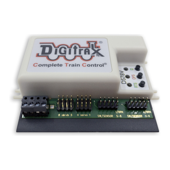
DS78V
Features:
▪
8 output channel LocoNet based Stationary decoder for operating eight
9G-type servo motors for turnout or general motion control.
▪
Plug-in connectors for simple and easy installation and service.
▪
User defined 8 consecutive switch (SW) addresses in 2000+ SW range.
▪
Stabilized 5 Volt servo drive voltages.
▪
Easy setup with Option Switches (OPSW) or LocoNet CV programming.
▪
Power input from 2mm DC jack, or DCC track voltage, 10V min to 20V max.
▪
16 easy to setup System Routes, with 8 SW Entries each.
▪
16 input control lines; 8 for Output/SW change and 8 Sensor/DS inputs.
▪
Additional advanced LocoNet Configuration modes using DT602 throttles.
Parts List
1 DS78V Stationary Decoder
1 Instruction Sheet
1.0 DS78V Quick Start - Eight servos, Thrown/Closed
The DS78V is simple to install and begin using on your LocoNet based layout.
1.
Figure 1 shows the recommended connections to operate the DS78V on
a LocoNet layout and to control up to eight mounted servos, like Digitrax
DSXSV9's.
2.
Connect a PS14 or similar DC 12V power supply to the DS78V via the DC
power jack. When powered the green ID LED should light and will briefly
wink OFF every 2 secs as a product 'heartbeat' showing the DS78V is opera-
tional. Alternatively, power from DCC feeder wires to the TKA/B terminals.
3.
Plug in an active LocoNet to a DS78V RJ12 connector. The red OPS LED
will light up showing connection. Any good LocoNet message seen will cause
the DS78V OPS LED to blink OFF briefly. With no LocoNet the unit will
respond to switch commands from a DCC track connection.
4.
Press and hold down the ID button for about 3 seconds until the RTS and
OPS LEDs blink alternately, then release the ID button.
5.
From your system send a SW command to set the Base Board address at this
SW#. The OPS and RTS LEDs will stop blinking showing the DS78V has set
the unit's Base SW# to the SW# you just sent, which is for Servo1 control.
6.
Plug in the servo 3pin connector(s) to the outputs you wish to control. The
connector brown wire will be closest to the DS78V beige case top.
7.
Operate turnouts with a SW# and direction Thrown (T)/Clockwise(CW) or
Closed(C)/Counter-Clockwise(CCW) settings at the; Base SW#, or the next
consecutive 7 SW#'s now in use by this DS78V.
That's all that's required for installation of your DS78V on LocoNet!
© 2021 Digitrax, Inc.
Complete Train Control
Run Your Trains, Not Your Track!
Eight Servo LocoNet Stationary/Accessory
decoder for turnout control
— 1 —
.
2 10-pin pluggable input cables
www.digitrax.com
Advertisement
Table of Contents

Related Manuals for Digitrax DS78V


Summary of Contents for Digitrax DS78V
- Page 1 LocoNet layout and to control up to eight mounted servos, like Digitrax DSXSV9's. Connect a PS14 or similar DC 12V power supply to the DS78V via the DC power jack. When powered the green ID LED should light and will briefly wink OFF every 2 secs as a product 'heartbeat' showing the DS78V is opera- tional.
- Page 2 To control eight servos driving 3-position semaphores using 16 switch addresses: Follow the steps of section 1.0 to power on DS78V and setup the Base SW#. Press and hold the OPS button for about 3 seconds until the green ID and RTS LEDs blink alternately.
- Page 3 2.0 Setup DS78V Servo angle Adjustment mode: The DS78V can be configured to conveniently drive all 8 servo outputs to the; T/ CW, Center or C/CCW servo angle positions for testing and installation. To go to Thrown/CW position: double click the RTS button with two quick presses and releases in less than 1 second.
- Page 4 4.0 Other DS78V Options: OPSW changes The DS78V configuration and behavior can be configured using 40 OPSW's. The Factory default OPSW settings will configure most common requirements. Press and hold the OPS button for about 3 seconds until the green ID and RTS LEDs blink alternately.
- Page 5 +5V ON voltage on the BLACK wire or pin10. If the DS78V is connected to LocoNet this will occur as a SW# message to make the change and notify the system it has occurred.
- Page 6 Chng adr are now no SW overlaps of DS7x devices after it. This "Chng Adr" to 33 for the 4th DS78V Base SW# just cleared the 3rd DS78V's active SW range (minimum is: 17+16 =33), fixing the problem. To identify the actual underlined fourth physical DS78V on the layout; press the F soft key "Ident"...
- Page 7 DT602 plugged into LocoNet, press the; Menu>3>4 keys to enter Route Editor menu. If any DS78V is on LocoNet, the DT602 will beep after about one second and show "DS7x" routes at the D soft key position.
- Page 8 OPSW8, as ms bit of CV11. The DT602 does not indicate to the DS78V when programming is complete. After finishing CV changes, best practice is to POWER cycle the DS78V to save changes. Alternately, you can WRITE CV7 to 00 to restart that DS78V.
Need help?
Do you have a question about the DS78V and is the answer not in the manual?
Questions and answers