Table of Contents
Advertisement
Quick Links
Super
Digitrax Command Control
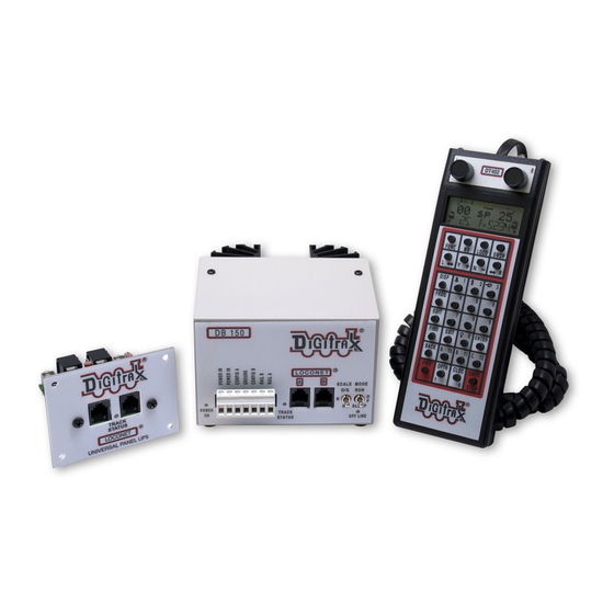
DB150 Command Station/Booster,
IR Operation with UR90, &
Radio Operation with UR91
Norcross, GA 30071 USA
(770) 441-7992 Fax (770)441-0759
Digitrax Manuals & Instructions are updated periodically.
Please visit www.digitrax.com for the latest version of all manuals.
This manual was updated 11/03.
Advanced
Starter Set
Manual
Includes:
DT400 Series Throttle,
UP5 Universal Panel,
D D i i g g i i t t r r a a x x , , I I n n c c . .
450 Cemetery ST #206
www.digitrax.com
D
R
igitrax
C
ommand
C
ontrol
Advertisement
Table of Contents
Troubleshooting

Related Manuals for Digitrax Super Empier Builder


Summary of Contents for Digitrax Super Empier Builder
- Page 1 D D i i g g i i t t r r a a x x , , I I n n c c . . 450 Cemetery ST #206 Norcross, GA 30071 USA (770) 441-7992 Fax (770)441-0759 www.digitrax.com Digitrax Manuals & Instructions are updated periodically. Please visit www.digitrax.com for the latest version of all manuals. This manual was updated 11/03.
-
Page 2: Table Of Contents
Digitrax Super Empire Builder Set Manual Includes DT400 Series Throttles, DB150 Command Station, UP5, IR Operations with UR90 & Radio Operation with UR91 Table of Contents 1.0 Introduction 2.0 Super Empire Builder Quick Start Guide Connect the DB150 to the track & transformer... - Page 3 Ground Terminal RAIL A & RAIL B Terminals TRACK STATUS Indicator OFF LINE Indicator 5.6.1 Troubleshooting DB150 Shutdowns CONFIG A & B LocoNet Connection Jacks A & B MODE Switch 5.10 SCALE Switch (O/G HO N) 5.10.1 Track Voltage Adjustment 5.11 DB150 Audible Sounds 6.0 DT400 Series Throttle Control Panel...
- Page 4 16.0 How Your DB150 Manages 22 Addresses 16.1 22 “Slots” For Addresses 16.2 Address Purging Strategy 17.0 Decoder Status 17.1 To Change the Status of a Decoder 17.2 Note for Non-Digitrax Decoder Users 18.0 Sw (Switch) Mode 19.0 Edit Fast Clock 19.1 Fast Clock Basics...
- Page 5 19.2 Stop the Fast Clock 19.3 Edit Fast Clock Time, Rate & Alarm 20.0 FIND Key & Digitrax Transponding 21.0 Shut Down and Resume Procedures 22.0 IR & Radio Receivers UR90 & UR91 22.1 Powering UR90 & UR91 Receivers 22.1.2 UR90/UR91Track Status Indicator Hook Up 22.2...
- Page 6 Digitrax, the Digitrax Train Logos, LocoNet, Empire Builder, Super Empire Builder, Chief, Super Chief, Zephyr, Jump and others are trademarks of Digitrax, Inc. This manual may not be reproduced in any form or translated into other languages without the express written permission of Digitrax, Inc.
-
Page 7: Introduction
One or more mobile decoders for your locomotives. This gives you the flexibility to choose the “right” decoder for your locos. Your starter set is just the beginning of an exciting trip. Digitrax will help you make your model railroading more enjoyable and more realistic. Your success with and enjoyment of our products are very important to us. -
Page 8: Super Empire Builder Quick Start Guide
U N I V E R S A L P A N E L U P 5 Notes: 1. This example shows a DB150 D T 4 0 0 Command Station. Any Digitrax Command Station can be used. 2. The DT400 throttle can be plugged in any LocoNet Throttle FUNC... -
Page 9: Connect The Db150 To The Track & Transformer
Connect the DB150 to the track & transformer S C A L E O / G 1. Set the DB150’s SCALE Switch to the scale you are running (N, HO, O\G). Use the lowest setting (N, HO, or O/G) that will run your layout. -
Page 10: Turn Track Power On
This screen shows the DT400’s software version number. It is displayed for a few seconds each time you power on the DT400. 3. Next you will see the power indicator screen: This screen indicates the power available to the throttle. When you are plugged in to LocoNet, this value will be between 9 &... - Page 11 1. When track power is off: DB150 TRACK STATUS indicator is off, DB150 OFF LINE indicator is on, and DT400 Track Power Indicator is off (Track Power Indicator is a small dot in the top line on the right side of the LCD). 2.
-
Page 12: Connect Your Layout To The Super Empire Builder
Connect Your Layout To The Super Empire Builder 1. Be sure both the TRACK STATUS indicator and POWER ON indica- tor on your DB150 are lit. 2. Connect the DB150’s RAIL A and RAIL B terminals to your track. Connect RAIL A to one rail and RAIL B to the other rail. 3. -
Page 13: Select & Run An Analog Loco On Address "00
throttle and one for the R Throttle. If the direction indicator is lit, and there is smoke over the loco icon there is an address select- ed on that throttle. 3. The direction indicator with blinking smoke indicates which throttle is currently active. The active throttle is the one for which function and text information is currently displayed on the LCD screen. - Page 14 “singing” caused by the DCC track signal when it is applied to ana- log locomotives. Once the analog loco is moving, this sound will change and be less noticeable. (Digitrax recommends that analog locos not be left sitting on DCC powered track for long periods of time when they are not running.)
-
Page 15: Decoder Address Basics
Digitrax decoders are set up at the factory with the “default” 03. This means that when you take a Digitrax decoder out of the package and install it in your loco, you can select address 03 on your throttle and run the decoder. The first CV programmed by most DCC users is the decoder’s address since it is not... -
Page 16: How To Select & Run A Dcc Equipped Loco
With some command stations, like the DCS100, you can read back the decoder’s address. See your Digitrax Decoder Users Manual for a complete discussion of decoder addressing. - Page 17 The illustration above shows the LCD after address “00” is selected on the R Throttle and address “03” is selected on the L Throttle, We see the Power On Indicator in the top line, the speed bar graphs at 0 speed and the text area also at 0 speed for both throttles.
-
Page 18: Shutting Down The System
2.10 Shutting Down the System When you are finished with your session, shut down the Super Empire Builder by turning off power to the system. Some users prefer to “dispatch” or release all addresses active in their system before shutting down. This can prevent unexpected results when you power up the layout again. -
Page 19: Quick Start Problems
Your Super Empire Builder Set is the gateway to all the possibilities and options offered by Digitrax so the best advice is to take it step by step and don’t try to do everything at once. The Digitrax Big Book of DCC is another excellent resource available to you as you expand your layout. -
Page 20: Loconet: The Digitrax Difference
DCC, such as detection systems and transponding, are not standardized. LocoNet incorporates both DCC and other technologies that expand the capa- bilities of your system. Your Digitrax system gives you the best of both worlds with a system that is compatible with today’s DCC “standards” and also goes beyond those “standards”... -
Page 21: Network Speed
Network Speed Is faster network speed better? Not necessarily, it depends on whether the sys- tem uses event driven or polled architecture. The DCC track control packet for- mat sets the “speed limit” for all DCC systems. Going faster than the “speed limit”... - Page 22 This LocoNet expansion example shows FN F0 MODE STOP some of the LocoNet devices you might add to your Digitrax System. With the Digitrax Command Contol F 3 F 7 F 3 F 7 F1 F1 F5 F5 F2 F2...
-
Page 23: Installing Digitrax On Your Layout
If the decoder in the locomotive does not “see” track power, it will not see the DCC signal and it won’t run. Digitrax boosters need enough track power to sense short circuits to operate properly. Your layout must have a power bus and feeder system that can safely support the continuous full current rating of any booster anywhere on the layout. -
Page 24: Other Track Wiring Considerations
feeders per power district. The actual wire gauges used (AWG) can be increased or decreased, depending on your actual layout dimensions and operating power/current loads. Other Track Wiring Considerations 1. Power connections to a large layout should be via a parallel conductor power bus similar to that used in most conventional layouts, with feeder wires to the track about every 6-10 feet. -
Page 25: Adding A Db150 Booster
How can I be sure I have enough power to run my trains? Use the “quarter trick.” Once your Digitrax booster is installed and the layout is powered up, use a quarter (or other piece of conductive material) to short both rails at vari- ous places on the layout. -
Page 26: Setting Up A Programming Track
To add a DB150 booster to your Super Empire Builder Set: 1. Start with an un-powered DB150. 2. Connect the DB150‘s CONFIG A & GROUND terminals with a short length of wire M O D E R U N 3. Set the DB150’s MODE switch to RUN S L E E P 4. -
Page 27: Reverse Section Wiring
DB150 and transformer. (Note: The DB150, when set up as a command station, cannot be set up to auto reverse.) If you use an automatic reversing device such as a Digitrax PM42 or one made... -
Page 28: Using A Db150 As An Autoreversing Booster
Take careful notice of the limitations of some of these non-Digitrax devices regarding auto reversing with steam locomotives. Using a DB150 as an AutoReversing Booster 1. -
Page 29: Using Pm42 For Power Management & Autoreversing
To handle auto reversing, you will need two devices, one that acts as the system polarity reference and another to detect a polarity mismatch and correct it. If you are using two DB150s (or other Digitrax boost- ers) one acts as the polarity reference and the other handles the polarity reversal for the reversing section. -
Page 30: Loconet Wiring Components
Some new Digitrax users believe it is very important to be able to switch between DCC & DC operation as they make the change from DC to DCC. In practice we find that most of these customers make the change much sooner that originally planned because of the opera- tional benefits of DCC. -
Page 31: Loconet Throttle Jacks & Loconet Connection Jacks
“reversing cable” in the telecom industry even though it really does not reverse). Most Digitrax dealers can supply or tell you where you can get the cable, plugs and crimpers you will need. Mail order electronic suppliers also have these components available. -
Page 32: Up5 Panel Hook-Up
4.13 UP5 Panel Hook-up Figure 5: UP5 Assembly & Hook-up UP5 Panel Assembly Front View Side View Panel Board T R A C K S T A T U S L O C O N E T U N I V E R S A L P A N E L U P 5 Silver screws Black screws on back of UP5... - Page 33 Type supply +12V Jacks 2 mm power jack to +15V DC (NOT connected center positive Throttles to DC power) (for example, RJ12 Digitrax PS12) Screw TelCo Terminals Jacks For Local Track Power LocoNet Connection 2 mm power Connections jack (connected...
-
Page 34: Troubleshooting Layout Wiring
Digitrax equipment from the layout and test it on a small section of track not connected to the layout to confirm that the problem is not with your Digitrax equipment. -
Page 35: Db150 Control Panel
(command stations.) When LocoNet is first powered up all Digitrax command stations check for other command stations also operating on LocoNet. The first command station that powers up will become the command station and all others will automati- cally operate as boosters. -
Page 36: Transformer
RAIL A & RAIL B Terminals Connect these terminals to the track on all Digitrax boosters and command sta- tions. If you are using more than one booster, always connect the same rail to... -
Page 37: Track Status Indicator
TRACK STATUS Indicator The “TRACK STATUS” “ indicator shows that there is voltage on the track. The color indicates the type of signal. If it is orange the track is getting DCC signals with no analog zero stretching. If the color is green or red then a “stretched zero”... -
Page 38: Loconet Connection Jacks A & B
LocoNet Connection Jacks A & B These LocoNet Connection Jacks let you expand your Digitrax system by sim- ply plugging LocoNet devices in to the system. MODE Switch The 3 MODE switch settings are: M O D E R U N RUN is for normal operations. -
Page 39: Db150 Audible Sounds
determine the approximate digital track voltage supplied. 5.11 DB150 Audible Sounds The DB150 uses several diagnostic beeps and clicks detailed below: TABLE II: DB150 AUDIBLE SOUNDS Sound Meaning 1 Beep DB150 has powered on successfully or has sent a programming command. 3 Beeps A loco address has been "purged"... - Page 40 Figure 6: DT400 Throttle Controls Infrared Flashlight LCD Display LEDs L Throttle R Throttle Knob Knob FUNC Key LOCO Key Press once to change Press to enter to Fn (function) mode D T 4 0 0 address selection mode. MU Key Press again to Press to enter select address.
-
Page 41: L(Left) & R(Right) Throttle Knobs
L(Left) & R(Right) Throttle Knobs Throughout this manual we refer to the throttle knob on the left side as the L Throttle and the throttle knob on the right side as the R Throttle. this corresponds to the L & R that appears on the throttle. The throttle knobs on the DT400 use “encoders.”... -
Page 42: Liquid Crystal Display (Lcd)
Liquid Crystal Display (LCD) Figure 7: DT400 LCD Functions 0-8 (Active Throttle) L Bar Graph R Bar Gragh Tetherless Indicator Track Power Indicator L Semaphore R Semaphore Text Area R Smoke Icon L Smoke Icon L Loco Icon R Loco Icon Mode L Throtte Direction R Throttle Direction... -
Page 43: Mode Indicator
Switch Accessory decoder control (turnouts, etc.) Status Edit Change locomotive speed steps to 14, 28, or 128 as needed Programming Paged-Digitrax preferred method Programming Physical Register Programming Direct Programming Operations Mode (Ops Mode) programming on the mainline. -
Page 44: L(Left) & R(Right) Throttle Display
The DT400 automatically defaults to the Loco mode (Lo) & returns to this mode after about 6 seconds of inactivity in MU or Switch modes. 6.3.5 L(Left) & R(Right) Throttle Display The decoder address selected on the L Throttle is displayed on the bot- tom line of the LCD to the left of the Mode Indicator. -
Page 45: Function Display
Bar Graph showing 0% speed on R Throttle 100% Bar Graph Speed Mark Bar Graph showing 50% speed on R Throttle Bar Graph showing full speed on R Throttle 6.3.8 Function Display Whether functions 0-12 are on or off for the currently active loco address is displayed on the top line of the LCD. -
Page 46: Tetherless Indicator
The L & R Semaphores are used when cab signaling is implemented on the layout. More information about signaling and detection will be avail- able on our web site, www.digitrax.com as these products become available. Information on how to activate these indicators will be included in the manuals for our detection and signaling products. -
Page 47: Mu Key
MU Key The MU Key is used to enter consist set up mode. Once the MU Key is pressed, you will be prompted by the throttle to use the Y+ Or N- Keys to add locos to or remove locos from consists. LOCO Key The LOCO Key , is used for selecting loco addresses on to the throttles so... -
Page 48: Disp Key
FIND FIND The FIND Key is used in conjunction with a layout instrumented for Digitrax Transponding and locos or cars equipped with transponders to find the location of those pieces of rolling stock on the layout. 6.14 BACK Key BACK... -
Page 49: Optn T Key
6.16 OPTN t Key OPTN The OPTN t Key is used to enter the Option Mode to set throttle and sys- tem options. It is also used to issue t (thrown) commands when the throttle in in Switch mode. In the case of turnout control: OPTN t=thrown, turnout is set for the diverging route through the curved leg. -
Page 50: Full Numeric Keypad
EMRG With global stop option enabled, pressing the EMRG STOP Key will STOP stop all locos on the layout and you will see the DT400’s track power indicator blinking on and off. To resume operations, press the PWR Key followed by the Y + Key to return locos to their speed prior to the EMRG STOP. -
Page 51: Infrared Emitters
6.22 Infrared Emitters Your DT400 has two infrared LEDs in the cable end of the throttle. These emitters send infrared signals that can be used by LocoNet compatible Infrared receivers to give you tetherless operation. See Section 22.0 for infrared opera- tion information. -
Page 52: Track Power Off
Simply press the Y + Key a third time to toggle back to system “GO” and track power on. Track Power Off When track power is off: DT400 Track Power Indicator is off ( the Track Power Indicator is a small dot in the top line on the right side of the LCD) DB150 TRACK STATUS indicator is off and DB150 OFF LINE indicator is on. -
Page 53: Dcc Address Ranges & Display
Lo mode indicator. The Text Area of the display will show the status of the last loco address selected (usually “stat 128” for Digitrax decoders). “Sel Loco” will be displayed in the Text Area if no loco address was previously selected. - Page 54 use just the R Throttle knob to browse from address 00(analog) to 01-127(2 digit addresses) to 0128-9983(4 digit addresses). NOTE: When you enter a four digit address from the key pad, the display will show the address as a two digit address and then a four digit address as you enter the numbers.
-
Page 55: Recall A Loco
4. To select a 2 digit address, use the keypad to enter the address of the loco you want to run OR turn the L throttle knob counterclockwise until you see 00 appear in the display, then use the R throttle knob to dial up a 2 digit address between 00 &... -
Page 56: Stealing: Forcing An Address Selection
numeric order. This makes it convenient to select locos that you have used pre- viously without having to dial up the address. To Recall the last 4, 8, or 16 addresses on the R Throttle 1. Press and hold the R Throttle knob. The word “Recall” will appear in the text line. -
Page 57: Slot Following
5. Press N - (or any other key) if you do not want to steal. Once a throttle has “stolen” a loco address, the slot following mode becomes active and both throttles will update speed and direction information for the loco address. -
Page 58: Locomotive Speed Control
9.0 Locomotive Speed Control To control the speed of a locomotive: 1. Select the loco address on either throttle 2. Turn the throttle knob clockwise to increase speed and counterclock- wise to decrease speed or 3. Use the Y + &... -
Page 59: Locomotive Direction Control
ated with that address to increase the loco’s speed. EMRG Press the EMRG STOP Key again to stop the loco that is associated STOP with the other throttle on the DT400. To resume operation, each operator must use their throttle to set their loco’s speeds back to the desired speed. -
Page 60: Controlling Functions
running on that throttle. Double click the L Throttle knob to reverse in the same way. Use the L or R Reverse Keys to reverse direction: Press the L & R Reverse Keys to reverse the direction of the locos selected on the respective throttles. -
Page 61: Function 0 (F0)
12.1.1 Function 0 (F0) Key Press the LAMP 0 Key to toggle F0 between on and off. Each time the LAMP 0 Key is pressed while in function mode, F0 will change from off to on or vice-versa. The top line of the LCD will display a 0 when the F0 is on and will be blank when F0 is off. -
Page 62: Controlling Functions On Consisted Locomotives
13.0 Multiple Unit Operations Digitrax Command Stations offer offer three methods of consist control: 1. The Basic Consisting method is to program all the locomotives in a consist to the same address and run them on one throttle. In this case all the locomotives must be headed in the same direction, head to tail, head to tail, head to tail. - Page 63 Since the address you will use to control the consist is not necessarily the address of the lead or head end loco, Digitrax has chosen the term “TOP” locomotive for this special address. It usually will be the train number.
- Page 64 locomotives are set up to move in the same direction and are not pulling against each other.) 5. Press the MU Key , the display will show the following: the MU mode indicator on the LCD display is lit. The loco address in the L side of the display will blink to show that it is the address that will be...
-
Page 65: Removing A Loco From A Consist
13.2 Removing A Loco From A Consist Radio & infrared throttles must be plugged into LocoNet to remove loco addresses from consists. To remove a loco address from a consist: 1. Select the loco address that you want to remove from a consist on the L Throttle. -
Page 66: Dispatching Addresses Or Consists
Radio & Infrared Throttles must be plugged in to LocoNet to release an addresses from your throttle. You can disable this safety feature by setting your DT400’s Op#3 to one of the values that allows tetherless release (See Section 25.2.2 for instructions). To release an address from a throttle: 1. -
Page 67: Programming And Configuration
Digitrax PR1 & your PC. The CVs are remembered in the decoder until it is reprogrammed to with a different CV value. Please refer to your Digitrax Mobile Decoder Manual for a complete listing of the CVs supported by each decoder. -
Page 68: Using The Dt400'S Key Pad In Programming Mode
mand station. The DB150 beeps once to indicate that it has sent the program- ming command. Power districts connected to expansion boosters will not receive the programming commands. 15.1 Using the DT400’s key pad in Programming Mode Before programming is discussed it is useful to explain how the DT400 enters CV numbers and values. -
Page 69: Programming Mobile Decoder Addresses
The following example shows how key pad entry works when you are entering CV Values: Use the DT400 key pad to enter CV Values while in Programming Mode Example: Key in a CV Value of 25 Press the "2 Key" CV Value of 002 is displayed Press the "5 Key"... - Page 70 The mode indicator in the center of the bottom line of the LCD shows which programming mode the throttle was using the last time it was in programming mode. Pg=Paged mode (Digitrax Preferred Programming Mode) Ph=Physical register mode Pd=Direct mode Po=Operations mode In ops mode, the left side of the display will show the address that will have programming commands directed to it.
- Page 71 . Digitrax recommends using the P , or Paged mode for program- ming all Digitrax decoders when using service mode on the pro- gramming track. If you are using non-Digitrax decoders you may need to change to a different mode if they are not capable of Paged mode.
-
Page 72: How To Program Other Configuration Variables
3. Select the programming mode by pressing the PROG Key until the method you want appears in the Mode Indicator. Digitrax prefers Paged Mode programming. 4. Turn the L Throttle to begin selection of the CV# you want to pro- gram. - Page 73 Use Paged Mode (P ) to Program CV02-Start Voltage To a CV value (dAt) of 045 (decimal) The symbol indicates that values entered by turning the R throttle knob or entering numbers from the keypad will appear in this side of the DT400's display. Remember that you can click the R Throttle to toggle the CV value display between decimal and hex as shown below.
-
Page 74: Operations Mode Programming
Your DT400 can use ops mode programming to change the CV value in ANY CV, including 2 digit and 4 digit addresses. All Digitrax Decoders that allow Ops mode programming can have their addresses changed with Ops mode pro- gramming. - Page 75 4. Use the L Throttle knob to dial up the CV you want to modify. Use the R Throttle knob to dial up the CV value you wish to program for the CV. This display shows a typical operations mode programming screen: 1.
-
Page 76: Busy Or Fail Message
trolled by the 2 digit or 4 digit address. To switch to the 2 digit address, program a value of 006/x06 into CV29. 2. Select the DCC loco’s 2 digit address on either the L or R Throttle. Be sure that the address you want to program is the active throttle, the one with the blinking smoke when you enter programming mode. -
Page 77: How Your Db150 Manages 22 Addresses
DCC signal. By refreshing the decoder’s data, the command station makes sure everything keeps running smoothly. Your Digitrax system classifies decoders as follows: Decoder Status Selectable Refreshed... -
Page 78: Address Purging Strategy
log on to the system where it left off. If the addresses previously in-use on the throttle have not been selected by other throttles the wayward DT400 will auto- matically re-log on to the purged locomotives and their status will be changed back to in-use. -
Page 79: To Change The Status Of A Decoder
Status editing is used most often when you are running non-Digitrax decoders that do not have 128 speed step capabilities. If you can’t get a non-Digitrax decoder to work on your layout and you are sure you are using the correct address for the decoder, you probably need to status edit it to run in 14 or 28 speed step mode. -
Page 80: Note For Non-Digitrax Decoder Users
“status edit” that locomotive to 14 speed step mode before running it with your Digitrax system. Changing the decoder’s status will cause the system to handle this decoder as a 14 step decoder. Status editing does not reprogram anything in the decoder. - Page 81 3. The LCD indicates the switch position using the c or t as follows: “t” indicates that the switch is “thrown” (for a turnout, the diverging route is set) “c” indicates that the switch is “closed” (for a turnout, the mainline route is set) If the “t”...
-
Page 82: Edit Fast Clock
Fast clocks during operating sessions to simulate prototypical operations. This clock is usually on the wall and is set to run at a faster than normal rate. LocoNet’s networked fast clock appears on all Digitrax throttles connected to LocoNet. The fast clock display is a 4 digit 12 or 24 Hour format clock. To display the... -
Page 83: Stop The Fast Clock
Display with FastClock showing 12:00am 1. Address 6104 running at 25% speed on the Left throttle in the reverse direction. 2. Address 25 running at 75% speed on the Right throttle in the forward direction. Blinking smoke shows that Address 25 is currently active in the display so its active functions, 0 &... -
Page 84: Find Key & Digitrax Transponding
To exit Edit mode at any time simply press the EXIT Key 20.0 FIND Key & Digitrax Transponding On layouts set up for Digitrax transponding with transponders in locos and rolling stock and transponder receivers installed on the layout, the DT400’s FIND Key is used to turn on the find command. -
Page 85: Shut Down And Resume Procedures
3. Select the address of the transponder you want to track on the active throttle on your DT400 (the one with the flashing smoke icon). Find can only be active for one address at a time. FIND 4. Press the FIND Key , the display will show a screen similar to one of the following examples: This example shows a DT400 in FIND... -
Page 86: Ir & Radio Receivers Ur90 & Ur91
For best operation, UR90, UR91 & all UP panels should be powered with a 12V DC external power supply such as the Digitrax PS12. You can run up to 5 UP or UR90 panels with a single 12-15V DC power supply. The UR91 abso- lutely must be powered with a 12V DC supply. -
Page 87: Ur90/Ur91Track Status Indicator Hook Up
22.1.2 UR90/UR91Track Status Indicator Hook Up Note: Hooking up the UR Track Status Indicators is OPTIONAL The UR Track Status Indicator is a bi-color LED that shows the status of the local track section to which it is attached. 1. Attach an 18-26AWG wire to one of the screw terminals on the back of the UR &... - Page 88 Figure 8: UP & UR Power...
-
Page 89: Installation Basics Ur90 & Ur91
Your Digitrax equipment gives you several ways you can make the observa- tions. You should choose the observation method that works best with your lay- out. -
Page 90: Ur90 Infrared Receiver Installation
LT1 Set Up As A Track Tester Led will be lit Yellow & White Black & Blue Green & Red wires not used Led will be lit You can also use a bi-color LED indicator lamp, with a 500 to 1k ohm resistor in series, connected to the two rails of the powered track. -
Page 91: Ur91 Radio Receiver Installation
1-2 feet away from them. 4. Plug the Digitrax PS12 +12 volt DC power supply into the 2.0 mm power jack on the side of the UR91. See Section 22.1 above for... - Page 92 5. Plug the UR91 into a LocoNet jack near where you plan to install it. We recommend that you start with a central location that will likely provide best coverage. 6. Power up the layout and track. 7. The Green LED on the UR91will be lit indicating the UR91 has passed its internal self-tests and is ready to receive radio signals.
-
Page 93: Resolving Radio Reception Problems
22.4.1 Resolving Radio Reception Problems Most layouts don’t experience problems with radio reception but, if you are having trouble, try the following suggestions for improving reception. 1. Electrical wiring, metal plumbing and A/C ducting and other items may cause areas of poor reception around the layout. This is typical- ly due to the multipath reflections or echoes of the radio waves. - Page 94 A 9 volt battery must be used to power the DT400/R for tetherless operation. Using DT400/R as a tetherless throttle is easy: 1. For Infrared operation, plug in at least one Digitrax IR receiver (UR90 or UR91) to your working LocoNet. Because infrared signals are line of sight, more than one receiver may be necessary for optimal performance in your layout room.
-
Page 95: Loconet Id Change
If an untethered DT400/R, operating as a tetherless throttle, detects no user throttle activity for about 3 minutes it will enter power save mode. The display will show: The throttle may flash the normal Fn Mode screen about every 60 seconds. This happens when the throttle “pings”... -
Page 96: Tetherless Operation
LocoNet to select a loco address. This is an important operational safety fea- ture. Digitrax chose not to allow one way address selection to prevent multiple operators from being able to select and send commands to the same addresses at the same time. - Page 97 Releasing a Locomotive Two options are available for tetherless release. These options are set by DT400 Option #3, see Section 25.2.2 for instructions. No tetherless release allowed: if the LOCO Key is pressed while LOCO LOCO the DT400/R is running in tetherless mode, the addresses selected will not be released unless the throttle is plugged in to LocoNet.
-
Page 98: Control Lock
fast time based on the last synchronized system fast time when the DT400/R was connected to LocoNet. If the fast time is edited by another throttle con- nected to LocoNet, the DT400/R will not see this change until it is plugged into LocoNet at which time its display will be updated. -
Page 99: Low Power Indicator
Batteries can be stored inside the DT400/R by removing the battery and putting it back in the battery compartment with the polarity reversed. 24.2 Low Power Indicator While it is running as a tetherless throttle, the DT400/R automatically checks the power available to the throttle each time a battery is inserted and each time it is plugged into or unplugged from LocoNet. -
Page 100: Battery Replacement
Figure 9: DT400/R Battery Installation Back of Remove Throttle battery cover by pressing here Battery Battery Compartment Cover and then sliding Correct installation the cover toward 9 Volt orientation for the bottom of Battery+ powering the throttle the case. Storage orientation 9 Volt (Polarity Reversed) Battery... - Page 101 format, the depth of the recall stack, the throttle ID#, and which radio frequen- cy the throttle will use. To make these changes, consult the following tables to determine which option values to set up in Option #1, Option #2, Option #3, Option #4, Option #F & Option #6.
-
Page 102: Dt400 Option #1
25.1 DT400 Option #1 25.1.1 Ballistic or Straight Line Tracking With ballistic tracking, the faster you increase or decrease the the throttle knob, the faster the data changes in the throttle. When ballistic tracking is enabled, so are typematic keys. With typematic keys, when you press and hold the Y + or N - Keys, the values will continue to increase or decrease without having to do a separate key press for each increment. -
Page 103: Dt400 Option #2
Table V: DT400 Throttle Option #1 Choices Op#1 Value (hex) Ballistic Key & Run/Stop Tracking & Knob Local/Global Typematic Clicks Keys Local x01 (Default) Local Local Local Global Global Global Global 25.2 DT400 Option #2 25.2.1 Throttle Default Decoder Operation Each DT400 can be set up to operate new decoders selected by that DT400as any decoder status code you choose. - Page 104 Table VI: DT400 Throttle Option #2 Choices Op#2 Throttle Default For Tetherless Value Decoder Operation Operation (hex) Mode 28 step decoder Radio & IR 14 step decoder Radio & IR 128 step decoder Radio & IR (DT400R) 28 step decoder IR Only Enabled 14 step decoder IR Only Enabled...
-
Page 105: Dt400 Option #3
25.3 DT400 Option #3 25.3.1 LCD Backlight Brightness Setting The backlight intensity can be set for off, low, medium or high intensity. The brightness of the backlight affects battery life, the brighter the LCD, the shorter the battery life. Note: When the DT400 is untethered, the backlight auto- matically reduces brightness by one setting to conserve battery power. - Page 106 Table VII: DT400 Throttle Option #3 Set Up Choices Op#3 Backlight Clock Recall Tether- Value Brightness Format Stack less (hex) Depth Release 12 hour format Low intensity 12 hour fomat Medium intensity 12 hour format High intensity 12 hour format 24 hour format Low intensity 24 hour format...
-
Page 107: Dt400 Option #4
Table VII: DT400 Throttle Option #3 Set Up Choices (Continued) Op#3 Backlight Clock Recall Tether- Value Brightness Format Stack less Depth Release 12 hour format Low intensity 12 hour format Medium intensity 12 hour format High intensity 12 hour format 24 hour format Low intensity 24 hour format... -
Page 108: Db150 Option Switch Setup
26.0 DB150 Option Switch Setup The DB150 has many customizable system operation options that you can set. The DB150’s power up defaults are fine for most applications and the DB150 will run just fine right “out of the box.” These options are provided for those individuals who want more flexibility in setting up their operations. - Page 109 Do not adjust any “reserved” option switches since this may give unpre- dictable operations. Any switches not listed in the table below should be considered “reserved”. *Special Instructions for DB150 Op Switches 36, 37, 38, & 39 For Op Switch #36-#39 to work properly, 1.
- Page 110 TABLE VIII: DB150 Option Switches Option Effect on System operation when "closed" Switch # OpSw 02 Booster only override OpSw 03 DB150's booster is auto reversing OpSw 05 DB150 is Command Station –Do Not Change OpSw 13 Purge time increased to 600 seconds OpSw 14 Purging is disabled OpSw 15...
-
Page 111: Troubleshooting
Do the settings in CV29, the configuration register, match the command station output? If your decoder is a 14 step decoder running on any Digitrax system using factory defaults, status editing will be needed for that decoder. Have you reset any CVs since the last time you ran the loco? If so, go back and change them to their default CV values and then try to run the loco. -
Page 112: Clean Track
again. Also check for localized track problems. Are there burn marks on the decoder? You’ll need to send it in for repair! If all else fails, reprogram the decoder address and reset CVs to default values. 27.4 Clean Track The majority of intermittent operation problems can be traced to bad connec- tions and poor or noisy wheel pickups on locomotives. -
Page 113: Mechanical Drive Train Problems
Do this by programming CV29 with a hex value of “06”. Refer to Section 15.3 for complete programming instructions. Your Digitrax decoder has been shipped programmed to 128 speed step mode. You may have changed your decoder’s programming when performing the decoder test procedure. - Page 114 4 Digit Address: decoder address between 0128 & 9983. Not all 4 digit addresses in this range are actually available for use. Your DT400 can access 0128 through 9983. Digitrax handles addresses below 0128 as two digit addresses to avoid confusion. Technically a 4 digit address is a 14 bit address and is considered an extended packet format DCC decoder address.
- Page 115 This feature is used to simulate train weight and to make your model respond more prototypically when you increase the throttle. Active throttle: Digitrax DT throttles are actually two throttles in one. Each handheld can control two different addresses or consists at a time one on the right side or R Throttle and the other on the left side or L Throttle.
- Page 116 Automatic analog mode conversion can be disabled by programming CV29. Autoreversing: a feature of Digitrax boosters that allows a train to enter and exit reversing sections automatically without the need for the operator to throw a switch to match track polarities on either side of the reversing section.
- Page 117 2. Whether or not the decoder will automatically convert to DC operation when no DCC signal is present 3. In the case of Digitrax FX decoders, the normal direction of locomo- tive travel 4. Whether the decoder uses loadable speed tables and 5.
- Page 118 & tells the turnout/accessory what to do. Decoder Status: the Digitrax command station assigns each decoder a status based on whether it is new to the system, in-use on a throttle, common in the system and available for selection or idle.
- Page 119 F0: Shorthand for Function 0. F0 is two functions in one. F0 Forward controls the white function lead and F0 Reverse controls the yellow function lead. Digitrax ships all decoders set up for automatically reversing head/tail lights using F0 Fwd and F0 Rev. These can be programmed to operate separately and be controlled by the operator if you do not want automatic operation.
- Page 120 Digitrax FX & 4th generation decoders go one step further and give you 128 speed step resolution with load- able speed tables. LocoNet: Digitrax’s powerful communications network especially designed for model railroad operation.
- Page 121 PWM: Pulse Width Modulation. R: Right throttle, Right reverse key, Right side of DT400 display. Refreshed (Data): Digitrax command stations re-send data to decoders many times to be sure that the signal is not lost and that you have reliable operation.
- Page 122 Status Editing Decoders: a DCC decoder’s status can be manually changed by a Digitrax command station at any time the decoder is selectable. Stealing a Loco: overriding the in-use interlock and forcing the throttle to select an in-use loco. This can result in having two throttles logged on to and controlling one address.
- Page 123 -Consult the dealer or an experienced radio/TV technician for help. Note that any modifications to the equipment not expressly approved by Digitrax voids the user’s authority to operate under and be in compliance with CFR 47 rules, as administered by the Federal Communication Commission.
- Page 124 All warranties on Digitrax products are limited to refund of purchase price or repair or replacement of Digitrax products at the sole discretion of Digitrax. In the event that Digitrax products are not installed or used in accordance with the manufacturer’s specifications, any and all warranties either expressed or implied are void.
- Page 125 66, 116, 119 Multiple Unit Operations 61 Connect the DB150 to the track & transformer 8 Connect Your Layout To The Empire Non-Digitrax decoder 79 Builder II 10 Consist 62, 113, 114, 117, 119 OFF LINE 9, 36 ops mode programming 25...
- Page 126 quarter trick 33 Quick Start 7 Rail A & B 10, 36 reversing section 26, 28, 115 RUN 8 SCALE 8, 37 service mode programming 25 short circuit management 28 Shutting Down the System 17 slots 76 speed control 56 status editing a decoder 121 Stealing 121 STOP key 57...
Need help?
Do you have a question about the Super Empier Builder and is the answer not in the manual?
Questions and answers