Table of Contents
Advertisement
Quick Links
Digitrax Command Control
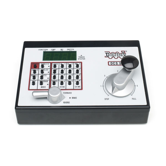
DCS50 Command Station Booster,
LT1 LocoNet Cable & Decoder Tester
450 Cemetery ST #206
Norcross, GA 30071 USA
(770) 441-7992 Fax (770)441-0759
Digitrax Manuals & Instructions are updated periodically.
Please visit www.digitrax.com for the latest version of all manuals.
This manual was updated 11/03.
Starter Set Manual
Includes:
PS315 Power Supply,
Digitrax, Inc.
www.digitrax.com
D
R
igitrax
C
ommand
C
ontrol
Advertisement
Table of Contents
Troubleshooting

Related Manuals for Digitrax Zephyr


Summary of Contents for Digitrax Zephyr
- Page 1 LT1 LocoNet Cable & Decoder Tester Digitrax, Inc. 450 Cemetery ST #206 Norcross, GA 30071 USA (770) 441-7992 Fax (770)441-0759 www.digitrax.com Digitrax Manuals & Instructions are updated periodically. Please visit www.digitrax.com for the latest version of all manuals. This manual was updated 11/03.
-
Page 2: Table Of Contents
1.0 Introduction 2.0 Zephyr Components 3.0 Preparing Your Locomotives 4.0 Preparing Your Layout 5.0 Zephyr Hook Up-As Easy As 1-2-3! 6.0 DCS50 Front Panel Controls And Indicators 7.0 DCS50 LED Display 8.0 Run A Locomotive Without a DCC Decoder 9.0 Run A DCC Equipped Locomotive 10.0 Shutting Down the System... - Page 3 Digitrax, the Digitrax Train Logos, LocoNet, Super Empire Builder, Super Chief, Transponding, SuperSonic, AutoReversing, Zephyr, Jump & others are trademarks of Digitrax, Inc. This manual may not be reproduced in any form or translated into other languages without Digitrax permission.
-
Page 4: Introduction
You will be able to run one locomotive without a decoder on your Zephyr sys- tem along with the ones with decoders. So, even if you don’t have a loco with a decoder, you can still hook up your new system and try it out right away! 4.0 Preparing Your Layout... -
Page 5: Zephyr Hook Up-As Easy As
For more information about layout wiring, see the Digitrax Big Book of DCC or visit our website at www.digitrax.com. 5.0 Zephyr Hook Up-As Easy As 1-2-3! These simple instructions will help you get up and running quickly. -
Page 6: Dcs50 Front Panel Controls And Indicators
1. Hook up the wires from the track to the RAIL A & RAIL B terminals on the DCS50. Insert the wire from one rail of the track into the RAIL A terminal on the back of the DCS50. Insert the wire from the other rail of the track into the RAIL B terminal. -
Page 7: Dcs50 Led Display
lever to FORWARD or REVERSE, the BRAKE INDICATOR will flash to let you know that the brake is released and the loco is accel- erating to the speed shown on the Throttle Knob. 3. There are 20 keys on the DCS50’s keypad, including a full numeric keypad. - Page 8 DCS50 Front Panel Diagram...
-
Page 9: Run A Locomotive Without A Dcc Decoder
Once the analog locomotive is moving, this sound will change and be less noticeable. (To avoid heat build up in your locos without decoders, Digitrax recommends that analog locos not be left sitting on DCC powered track for long periods of time when they are not running.) -
Page 10: Run A Dcc Equipped Locomotive
F U N C T I O N J U M P S W I T C H Display is blinking 5. Press the LOCO Key again to confirm your selection and set address 00 on the throttle. The display will stop blinking and you will have control of the analog locomotive. - Page 11 3. To select a DCC locomotive and run it, you must know its address. 4. Digitrax decoders are set up at the factory with address 03. This means that when you take a Digitrax decoder out of the package and install it in your loco, you can select address 03 on your throttle and run the decoder.
-
Page 12: Shutting Down The System
(0-8) for the function you want to operate. 10.0 Shutting Down the System When you are finished with your session, shut down the Zephyr by turning off power to the system. -
Page 13: Resuming Operation
2. If you still have problems or if you have other questions or problems, we encourage you to call, fax or e-mail your favorite Digitrax dealer. If your dealer is not able to help, please contact Digitrax directly. There are thousands of successful Digitrax installations around the world and we want to be sure that yours is one of them. -
Page 14: Decoder Programming
Digitrax and LocoNet so the best advice is to take it step by step and don’t try to do everything at once. The Digitrax Big Book of DCC is an excellent resource available to you as you expand your lay- out. -
Page 15: Setting Up A Service Mode Programming Track
To use this mode, you must have decoders that are capable of operations mode programming. Programming with LocoNet Throttles on a Zephyr is easy. All LocoNet throttles will program as though they were connected to a DCS100 Command station. -
Page 16: Using The Programming Track To Change The Decoder Address
2. Press the PROG Key to enter programming mode. The DCS50 will display one of the programming modes available. Digitrax recom- mends the Paged Mode when you are using the programming track. If you press the PROG Key repeatedly, you will cycle through the following choices. - Page 17 If you are not using Paged programming, see Table I: DCS50 Programming Display Table below for information about how your display will be different from this example. 3. Press the LOCO Key and you will see either Ad2 or Ad4. Ad2 = two digit address Ad4 = four digit address Each time you press the Loco Key the display will toggle between Ad2...
-
Page 18: Using The Programming Track To Program Cvs Other Than Addresses
2. Press the PROG Key to enter programming mode. The DCS50 will display one of the programming modes available. Digitrax recom- mends the Paged Mode when you are using the programming track. As you press the PROG Key repeatedly, you will cycle through the following choices. - Page 19 F U N C T I O N F U N C T I O N J U M P S W I T C H The numbers will flash for a few seconds as the command station reads back the data value in the decoder. The d means that you are looking at the CV’s data value that is programmed into the decoder, in this case the CV value is 0.
-
Page 20: Programming On The Mainline: Operations Mode Programming
J U M P S W I T C H F U N C T I O N J U M P S W I T C H Paged Mode Digitrax Preferred Method Press PROG Key Press CV Key Press CV-RD Key... -
Page 21: Programming Error Messages
How to use Operations Mode Programming 1. Place the loco you want to program on the layout. 2. Select the address of the operations mode capable decoder equipped loco that you want to program on the local throttle of the DCS50. 3. -
Page 22: Reading Back Cv Values Programmed
Most likely, you will use your programming track for reading back CV data values. You can also do Ops mode read back with Digitrax transpond- ing decoders if you have a LocoNet device that allows ops mode read back plugged in to LocoNet. -
Page 23: Locomotive Speed Control
F U N C T I O N F U N C T I O N J U M P S W I T C H 4. Enter the CV number you want to read back. If you want to read back the decoder’s address, press the LOCO Key to toggle between Ad2 and Ad4. -
Page 24: Locomotive Direction Control
current speed limit set for this DCS50. We recommend a value in the range of 26 (lowest speed limit) to 99 (full speed limit). DCS50 is shipped from the factory set for SP99. F U N C T I O N F U N C T I O N J U M P S W I T C H... -
Page 25: Brake Operation
15.2 Brake Operation To use the pre-set braking rate to stop and start a locomotive: Move the DIRECTION LEVER to the BRAKE position and the loco will slow down to a stop at the brake rate you have set up in the DCS50. -
Page 26: Emergency Stop
15.3 Emergency Stop To stop everything on the layout immediately: Press the POWER Key to turn off power and stop the whole layout. This option will stop everything on the layout. Having Trouble Stopping? If the deceleration CV value you set for a particu- lar loco is very large, this can make it look like the loco is not stopping on command because the deceleration CV value is causing the loco to take a long time to come to a stop. -
Page 27: Functions 1, 4, 5, 6, 7
16.1.2 Functions 1, 4, 5, 6, 7, & 8 Press the number key on the numeric keypad that corresponds with the function number you want turn on/off. The function will toggle between on and off each time you press the number key. The BELL 1 Key is used for function 1 and is labeled with a bell icon to remind you that this is the preferred function key for bell operation. -
Page 28: Function Operation Troubleshooting
See your Digitrax Decoder Manual for information about how to change the Normal Direction of Travel. -
Page 29: Adding A Locomotive To An Mu
Your DCS50 uses universal consisting so that MU operations are simple and easy to do. This is the most flexible and realistic method of MU’ing available. You can add any locomotive to your MU, no mather what kind of DCC decoder is in your loco. -
Page 30: Removing A Loco From An Mu
revert to the address of the TOP locomotive and you can run your MU. To run your MU, just turn the THROTTLE KNOB to set the speed and use the DIRECTION LEVER to change directions. Use the NUMERIC KEY pad to control the functions on the MU’ed locos. -
Page 31: Mu Of Mismatched Locomotives
Simple 3 step or Advanced 28 step loadable speed tables (See your Digitrax Decoder Manual for more information on these features). -
Page 32: Stealing: When An Address Is Running On Another Throttle
18.0 Stealing: When An Address Is Running on Another Throttle Digitrax systems do not allow more than one user to select and run the same locomotive address unless the loco is “stolen” by the new user. When an address is receiving commands from more than one throt- tle, it may seem to be out of control. -
Page 33: Releasing An Address From A Throttle
cially if one throttle is trying to to stop the loco and the other is try- ing to speed it up at the same time. When you have gained control of the stolen loco and are finished run- ning it, release it from your throttle by setting the loco’s speed to 0 and pressing the LOCO Key followed by the EXIT Key. -
Page 34: The Full Message
When you dispatch a locomotive address or MU to your LocoNet system, you make it available to be acquired by another throttle. Only one address at a time can be marked as a dispatched address in the system. The dispatched loco address is acquired by the first throttle to request it by pressing the ACQ key to select it for use on that throttle. -
Page 35: Dcs50 Error Messages
Within the DCC format there are several ways decoders and command stations communicate speed step information. All of your decoders and your command station must be “speaking the same dialect of the DCC language” for every- thing to work smoothly. Digitrax DCS50 is set at the factory to send 128 speed... -
Page 36: Changing Speed Step Settings: Status Editing
Some non-Digitrax decoders use other speed step formats and won’t respond to your DCS50 sending 128 speed step information. If you have a non-Digitrax decoder that can’t run in 128 speed step mode, you can change the number of speed steps the DCS50 is sends to that decoder so that you will be able to control the decoder. -
Page 37: Switch Mode
This indication does not guarantee turnout position since, the turnout may have been moved by hand and the DCS50 has no way of determining actual turnout position. Digitrax uses the following convention for position information for turnouts:... -
Page 38: Adding Throttles: Loconet & Jump Ports
indicates that the switch is “thrown” (for a turnout this means that the diverging route is set) indicates that the switch is “closed” (for a turnout this means that the mainline route is set) The examples below show turnout address 087 first closed and then thrown F U N C T I O N J U M P... -
Page 39: Jump Ports: Using A Smooth Dc Power Pack As An Additional Throttle
capacity for running up to 120 throttles. You can continue to use your DCS50 as a throttle and booster with either set. 24.2 Jump™ Ports: Using A Smooth DC Power Pack As An Additional Throttle DCS50’s Jump A & B ports can host two DC power packs as additional throttles. - Page 40 This configuration gives you three throttles to control three loco address- es or MUs. 1. The throttle knob and direction lever on your DCS50 is called the LOCAL THROTTLE. 2. The throttle and direction controls on each of the smooth DC power packs you are using are called respectively, JUMP 1 and JUMP 2.
- Page 41 To run a loco address on Jump Port 1: 1. Press the JUMP Key until you have JUMP 1 in the display, you’ll see the Jump Indicator Dot on steady and a screen like this if there is nothing selected on Jump 1. F U N C T I O N J U M P S W I T C H...
- Page 42 Steady Jump Indicator Dot means Jump 1 is in the display. F U N C T I O N J U M P S W I T C H Steady Function 67 in the display Indicator Dot means Loco address means that the 67 is currently DCS50 keypad...
-
Page 43: Adding Another Dcs50
THROTTLE. The JUMP 1 power pack will continue to control speed and direction of the loco address selected on the JUMP 1 throttle. 24.3 Adding Another DCS50 Since each system only needs one command station, you only need one DCS50 performing this function. When you are ready to add one or more additional DCS50s to the system, you’ll need to disable the command station feature of the additional units. -
Page 44: Making Loconet Cables
LocoNet cables. The LT1 tester that came with your Zephyr can be used to test LocoNet cables to be certain they are good before you install them on your layout. Many layout problems we see are related to LocoNet cables that were not built or crimped correctly. - Page 45 Adding A Second DCS50 To Your Layout...
-
Page 46: Shut Down Procedures
2. Plug one end of the LocoNet cable being tested into the LT1. 3. Connect the other end to any powered Digitrax booster LocoNet Port A or B. Be sure you have at least one Digitrax throttle connected to LocoNet. -
Page 47: Troubleshooting
Pay attention to the mechanical drive train and free movement of the locomo- tive wheel sets. This is especially important with inexpensive locomotives. Using Digitrax decoders with appropriate programming settings, you can achieve surprisingly good quality motion, if you carefully adjust the mecha- nisms for smooth running. -
Page 48: Decoder Won't Respond
DCS50 in its optimum 128 speed step mode. If you have a Digitrax Series 3 decoder and you can control the lights but not the motor, check for a motor short circuit. These decoders are designed to shut- down motor operation when a short is detected to prevent damage to the decoder. -
Page 49: I'm Totally Lost
Was the loco running normally just before it stopped? If the decoder is very warm it may be in thermal shutdown. Let it cool off and see if it starts again. Also check for localized track problems. Are there burn marks on the decoder? You’ll need to send it in for repair! If all else fails, reprogram the decoder address and reset CVs to factory original values. - Page 50 3. Press the SWITCH Key. The display shows the last switch used by the DCS50 and its commanded position. 4. Use the NUMERIC KEYPAD to enter the number of the Option Switch you want to change. 5. Press the c or t key to set the OpSw to the setting desired. 6.
- Page 51 DCS50 Option Switch Table Option Effect on System operation when "closed" Factory Switch # Setting OpSw 01 c=1 Jump Port t=2 Jump Ports OpSw 02 c=DCS50 runs as booster/throttle with no command station capability OpSw 03 c=DCS50's booster is auto reversing OpSw 05 c=No change allowed for Throttle ID, Vmax or Brake Rate...
-
Page 52: Loconet: The Digitrax Difference
With LocoNet, you customize your layout to run the way you want it to run! There is a lot of information available to help you along the way. The Digitrax Big Book of DCC shows you how to implement DCC on your layout by using examples of actual layouts and showing you how they work. -
Page 53: Fcc Information
29.0 FCC Information Radio or TV Interference: (this information is MANDATED by the FCC) This equipment has been tested and found to comply with the limits for a Class B digital device, pursuant to part 15 of the FCC rules. These limits are designed to provide reasonable protection against harmful interference in a res- idential environment. -
Page 54: Warranty And Repair Information
-Consult the dealer or an experienced radio/TV technician for help. Note that any modifications to the equipment not expressly approved by Digitrax voids the user’s authority to operate under and be in compliance with CFR 47 rules, as administered by the Federal Communication Commission. - Page 55 All warranties on Digitrax products are limited to refund of purchase price or repair or replacement of Digitrax products at the sole discretion of Digitrax. In the event that Digitrax products are not installed or used in accordance with the manufacturer’s specifications, any and all warranties either expressed or implied are void.
- Page 57 Preparing Your Locomotives 3 Horn 2 Key 26 PROG A & B 4 How To Select & Run A DCC Programming Error Messages 20 Equipped Loco 9 Programming On The Mainline 19 Programming with LocoNet Throttles on a Zephyr 14 Intermittent Operation 46...
- Page 58 Warranty and Repair 53 Rail A & B 4 Reading Back CV Values 21 Releasing An Address From A Throttle Zephyr Hook Up 4 Removing A Loco From An MU 29 Resuming your session 12 Run A DCC Equipped Locomotive 9...
Need help?
Do you have a question about the Zephyr and is the answer not in the manual?
Questions and answers