Table of Contents
Advertisement
Advertisement
Table of Contents

Related Manuals for SP Scientific LYOSTAR II


Summary of Contents for SP Scientific LYOSTAR II
- Page 1 ’ YOPHILIZER PERATOR ANUAL FTS S ™ II YSTEMS TANDARD...
- Page 3 The information in this document is subject to change without prior notice. Always confirm with SP Scientific that you are using the most current version of this document. SP Scientific is free to modify any of its products and services, in any manner and at any time, notwithstanding the information contained in this document.
-
Page 4: Important Symbols
Never use acrylic closures if they are cracked or crazed. Never use with toxic, corrosive, flammable or organic materials unless special precautions are in place to prevent injury to personnel or damage to equipment. Rev 012, 04/11 © SP Scientific 2011... -
Page 5: Warranty Information
Limited Warranty SP Scientific (the “Company”) shall warrant each of its products against defects in material or workmanship for a period of 12 months from the date of installation or 15 months from the date of shipment (whichever comes first) provided that the product is used in a reasonable manner under appropriate conditions and consistent with the applicable operating instructions. - Page 6 Rev 012, 04/11 © SP Scientific 2011...
-
Page 7: Table Of Contents
Automatic Run ..............................18 Background ..............................18 Basic Operation ............................. 18 Programming Tips ............................19 To Create a New Recipe: ..........................19 To Change the Recipe While the System Is Executing the Program: ............22 Rev 012, 04/11 © SP Scientific 2011... - Page 8 Placement and Initial Set-Up..........................49 General Maintenance ....................51 Synoptic Screen ..............................51 Maintenance Screen ............................52 Tune ................................54 Calibration of Product Thermocouples ......................55 System Maintenance ............................56 Appendix A: Troubleshooting ..................59 Rev 012, 04/11 © SP Scientific 2011...
-
Page 9: Introduction
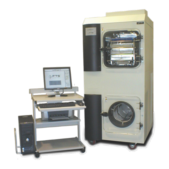
Chapter Introduction Overview The LyoStar II research and development freeze dryer is comprised of 4 major components: Tray chamber Condenser chamber Computer workstation Vacuum pump (accessed thru lower left door) Rev 012, 04/11 © SP Scientific 2011... - Page 10 Double click the LyoManager icon on the desktop. Click Lyobrary on the main menu and acquaint yourself with system operation by reviewing this presentation. Rev 012, 04/11 © SP Scientific 2011...
-
Page 11: Getting Started
Should damage or loss be discovered, you may make a written request for inspection by the carrier's agent within 15 days of the delivery date. You may then file a claim with the freight carrier or SP Scientific, depending on the terms of your shipment. -
Page 12: System Checklist
Getting Started FTS Systems LyoStar™ II System Checklist After the LyoStar II is in place, and before operation of the equipment, make certain of the following, • The main electrical line cord from the LyoStar II is plugged into the correct power outlet (check serial tag against wall voltage). -
Page 13: Heat Transfer Fluid-Initial Set-Up
Getting Started Heat Transfer Fluid—Initial Set-up The Heat Transfer Fluid reservoir is located in the top rear of the LyoStar II. The fluid circuit is a sealed system that requires no additional fluid to be added to the unit under normal setup or operating conditions. -
Page 14: Cooling Water Requirements (Water Cooled Units Only)
2-4 gpm. When the system is off, the water flow will stop. This will conserve water if the unit is connected to a municipal water supply. Please do not operate the LyoStar II with cooling water above 86°F (30°C). The unit will add approximately 20,000 BTUs/hour at steady state to your facility water. Peak demand could be as high as 25,000 BTUs/hour. -
Page 15: Door Closure
Condenser drain port is closed. Door Closure The black rubber gasket for the front door of the LyoStar II has been designed so that no vacuum grease is necessary for system operation. Vacuum grease should not be placed on this gasket for any reason. If the gasket shows any signs of cracks or tears replace it immediately. - Page 16 If removable bottom trays are used, samples are removed by reinserting the tray bottoms under the sample containers and removing them from the chamber. Rev 012, 04/11 © SP Scientific 2011...
-
Page 17: Operating Your Lyophilizer
If this still results in poor test performance SP Scientific Service should be contacted. These baseline specification runs should be performed before any product is processed in the freeze dryer. - Page 18 Synoptic – Mechanical representation of the LyoStar showing the current machine state • The Lyobrary – Collection of freeze-drying articles and warranty info • Instructions – Instructions of machine operation • Quit – Exit program Rev 012, 04/11 © SP Scientific 2011...
- Page 19 Freeze-Drying – Screen to input recipe for automatic freeze-drying process • Defrost – Defrost the condenser coil • System Test – Tests the integrity of the system • Leak Rate – Calculates the leak rate of the vacuum system (mTorr/hr) Rev 012, 04/11 © SP Scientific 2011...
-
Page 20: Leak Rate Testing
Select Leak Rate test from the menu. The Leak Rate Test screen will now be displayed. Enter values to test the performance of the unit. The values SP Scientific uses during QC testing are shown here. Values may be altered but should be run consistently thereafter to accurately compare performance from run to run. -
Page 21: System Testing
From the Automatic Mode Select screen, select System Test from the menu. The System Test screen will be displayed on the screen. Enter values to test the performance of the unit. The values SP Scientific uses during QC testing are shown here. Values may be altered but should be run consistently thereafter to accurately compare performance from run to run. -
Page 22: Thermocouple Placement
When possible, the sample with the thermocouple should be placed in the center of the product tray. SP Scientific also offers a variety of Special Product Sensors, which fit serum bottles with either a 13 mm or 20 mm neck. These product sensors are highly recommended as they are easily fitted to bottles and vials and provide repeatability. -
Page 23: Manual Mode Of Operation
From the Main Menu screen, select the Manual mode of operation. The Manual screen will be displayed Click to change Shelf or Vacuum setpoints Click on the Power button. This button enables all functions in the manual mode. Rev 012, 04/11 © SP Scientific 2011... - Page 24 Power. During Backfill, air or nitrogen will enter the system through the product chamber only. During Release, air or nitrogen will enter the system through both the product chamber and the condenser. Rev 012, 04/11 © SP Scientific 2011...
- Page 25 Note: Isolate closes the butterfly type isolation valve located between the product chamber and the condenser. When closed, the product chamber is isolated from the vacuum pump. The isolation valve can be used to perform manual pressure rise testing. Rev 012, 04/11 © SP Scientific 2011...
-
Page 26: Automatic Run
The Recipe Screen for Freeze-Drying process screen will be displayed. To use an existing run click on the Existing recipe button. A window will open showing all of the existing runs. Highlight the one that you want. Rev 012, 04/11 © SP Scientific 2011... -
Page 27: Programming Tips
Steps in freezing and drying are enabled by clicking on the yellow box which displays the number for each step. The yellow background will change to green and data entry will be enabled. Rev 012, 04/11 © SP Scientific 2011... - Page 28 Note: Use the software to perform step 9. Do NOT use the condenser drain valve to break vacuum. This sudden change to atmospheric pressure is not recommended for the capacitance manometer. You may view current data from various screens: Rev 012, 04/11 © SP Scientific 2011...
- Page 29 FTS Systems LyoStar™ II Operating Your Lyophilizer Rev 012, 04/11 © SP Scientific 2011...
-
Page 30: To Change The Recipe While The System Is Executing The Program
40 more minutes for a total of 50 minutes. • Shelf temperature and vacuum setpoints can be changed at any time during a cycle. Note: For printing or exporting data please see the Data Management section of this instruction manual. Rev 012, 04/11 © SP Scientific 2011... -
Page 31: Data Management
Manual Cycles • Alpha numeric data generated during a manual run is also logged. System Test—alpha numeric data generated during a system test indicates Phases #51-58 if allowed to run through to completion. Rev 012, 04/11 © SP Scientific 2011... -
Page 32: Export To Spreadsheet
If the data collection window is inadvertently closed during a run, data will still collect uninterrupted. Reopen the viewing window by going to the Historical main menu and clicking on the orange tab entitled Alpha Numeric Data Files. Rev 012, 04/11 © SP Scientific 2011... -
Page 33: Graphical Display
From here you have a choice of viewing in 5 min, 15 min, 30 min, 1 hr, 6 hr, or 12 hr intervals. There is also the ability to specify the time duration you would like to see. Rev 012, 04/11 © SP Scientific 2011... - Page 34 Next release the right mouse button and the graph will redraw itself. To reset the graph back to normal press the Reset Zoom button located at the top of the screen. Rev 012, 04/11 © SP Scientific 2011...
- Page 35 The limit of the axis is based on the working range of the sensor. Rev 012, 04/11 © SP Scientific 2011...
- Page 36 Data Management FTS Systems LyoStar™ II To print a graph, click on a time under duration or specify the date. Click the print button at the top of the graph. Rev 012, 04/11 © SP Scientific 2011...
-
Page 37: Defrost
Note: Care should be taken to ensure the drain valve is closed after draining the condenser. Verify by turning handle fully clockwise. Rev 012, 04/11 © SP Scientific 2011... - Page 38 Data Management FTS Systems LyoStar™ II Rev 012, 04/11 © SP Scientific 2011...
-
Page 39: Optional Liquid Nitrogen Trap-Auto Filling
The auto filling liquid nitrogen trap is connected to a LyoStar II when it is important to trap these high vapor pressure solvents. Typically, these solvents come off the product early in the drying cycle. -
Page 40: Utility Requirements
CLOTHING IS REQUIRED. WARNING: INERT GASES RELEASED IN A CONFINED SPACE AN DISPLACE SUFFICIENT AIR TO MAKE THE ATMOSPHERE INCAPABLE OF SUSTAINING LIFE. ENTERING AN OXYGEN DEFICIENT ATMOSPHERE MAY CAUSE UNCONSCIOUSNESS WITHOUT WARNING. Rev 012, 04/11 © SP Scientific 2011... -
Page 41: Operation
Note: If cover is not seated, the proximity sensor will prevent the solenoid from opening. When the liquid level reaches 4 inches, the controller will shut the solenoid. To put the trap on-line, open the inlet and outlet valves and close the bypass valve. Rev 012, 04/11 © SP Scientific 2011... - Page 42 To by-pass, simply open the by-pass valve and close the inlet and outlet valves. When liquid nitrogen is no longer needed, shut off the supply line then depress the fill button several times to bleed supply line. Rev 012, 04/11 © SP Scientific 2011...
-
Page 43: Cleaning
Drain the condensate using the drain line then wipe out the outer reservoir. Once cleaned, loosen the thumbs screws again and lower the lid. Align and secure the latches. Carefully lower sensor all the way back into the reservoir. Rev 012, 04/11 © SP Scientific 2011... -
Page 44: Side Wrapper Removal
The hoses are long enough to set the wrapper on the ground. Use caution not to put excessive tension on either of the vacuum lines. The upper connection is routed to the vacuum pump and the lower to the condenser. Rev 012, 04/11 © SP Scientific 2011... -
Page 45: Optional Sample Extractor Assembly
The SEA is a pivotal option when the operator’s mission is product development or stability studies. Description The SEA is mounted on a modified acrylic door of the LyoStar II. It consists of • Acrylic vacuum antechamber with stoppering ram •... -
Page 46: Sea Installation Instructions
Open the standard door. An assistant should take position to support the door. Remove the upper and lower quick release pins. Remove the standard door. Quick Release Pins Note: The quick-release pins may be saved for replacement pins. Rev 012, 04/11 © SP Scientific 2011... -
Page 47: Sea Installation
With help from an assistant, align the SEA in the hinge brackets. Re-install the quick release pins. Re-install the front plate with selector arm. Extractor door without front antechamber cover and selector arm. Rev 012, 04/11 © SP Scientific 2011... -
Page 48: Operation
Push the button to open the jaws and release to close them. Place the sample(s) in the antechamber directly beneath the stoppering ram. Press to stopper Lower handle to lock shut Rev 012, 04/11 © SP Scientific 2011... - Page 49 Loosen the thumb screws and slide the front plate down until it can be opened. Open front plate to remove the vials Remove the stoppered vials. Close the front plate to reseal the chamber for the next run. Rev 012, 04/11 © SP Scientific 2011...
-
Page 50: Shelf Area
Note: Latching one shelf up will position the other shelves so that a 20 mL vial can be used and increases the accessible shelf area to 240 sq.in. This configuration requires vials to be rotated 90 degrees, to a horizontal position, to be removed. Electrical Requirements LS-FD-SEA 120V/60hz 6 Amps Rev 012, 04/11 © SP Scientific 2011... -
Page 51: Optional Isolation Valve
1 and 4 inches of liquid nitrogen in the reservoir. There are low and high level alarms preset at 0 and 6 inches. See the liquid level controller manual for operating details. Rev 012, 04/11 © SP Scientific 2011... - Page 52 Optional Isolation Valve FTS Systems LyoStar™ II Rev 012, 04/11 © SP Scientific 2011...
-
Page 53: Optional Shelf-Latching Kit
Shelf latching kits are available for each system. These kits can be used with the LyoStar II shelf assembly to create moveable shelf stacks. The primary use of the shelf-latching system is to facilitate the stoppering of product vials; however, the shelf latching kits may also be used to increase the distance between shelves when processing product in large vials. - Page 54 Optional Shelf-Latching Kit FTS Systems LyoStar™ II Secure wing nuts. Using the stoppering switch return the two available shelves to their full down position. The shelves are then available for loading Rev 012, 04/11 © SP Scientific 2011...
-
Page 55: Optional Cleanroom Configuration
Chapter Optional Cleanroom Configuration Overview The following notes the deviations from the standard LyoStar II configuration, and can be applied to any software package in the LyoStar II family. The LyoStar II research and development freeze dryer cleanroom configuration is comprised of four major components. - Page 56 Optional Cleanroom Configuration FTS Systems LyoStar™ II Major Cleanroom Components Product Chamber Right Shelves Condenser Condenser Chamber Drain Port Electrical Box Hour Meter and Fuse Panel Left System UPS Vacuum Pump Hydraulic Pressure Gauge Rev 012, 04/11 © SP Scientific 2011...
-
Page 57: Placement And Initial Set-Up
In most cases, the wall flange can be sealed and secured to the wall using clear RTV and #10 x 1 ½” long, stainless steel, pan head wood screws. Rev 012, 04/11 © SP Scientific 2011... - Page 58 Optional Cleanroom Configuration FTS Systems LyoStar™ II Rev 012, 04/11 © SP Scientific 2011...
-
Page 59: General Maintenance
The synoptic screen icons will indicate their status, off or on, with a message next to each pictured component. Note: Only qualified personnel should control the machine while in maintenance mode, since one can potentially harm the components. Rev 012, 04/11 © SP Scientific 2011... -
Page 60: Maintenance Screen
Note: The maintenance screen can only be activated when there are no other runs in progress. Click the Enable button to operate the screen. Here one may turn components on and off at will. Rev 012, 04/11 © SP Scientific 2011... - Page 61 Example: In this case we want to turn on the shelf fluid pump so we will click on the fluid pump image. A screen will pop up that describes this pump. Press on the ON button to turn the pump on. Rev 012, 04/11 © SP Scientific 2011...
-
Page 62: Tune
Tune The Tuning screen is used to finely adjust the control system. Do not change these values without first speaking to SP Scientific service or engineering. Rev 012, 04/11 © SP Scientific 2011... -
Page 63: Calibration Of Product Thermocouples
-4095 to 4095. After the values are entered, one can hit the Manual Calibration button and the system will accept the values. After calibrating, one may save to the disk to load at a later date. Rev 012, 04/11 © SP Scientific 2011... -
Page 64: System Maintenance
Visually inspect all hose's, Vacuum, Hydraulic, Air and fluid drain lines for signs of deterioration, replace as necessary. Check Voltage (Correct ± 5%). Problems arise due to incorrect supply voltage or from seasonal voltage drops. Yearly Replace Sterile Air filters (qty 2). Rev 012, 04/11 © SP Scientific 2011... - Page 65 Please see the vacuum pump manual for instructions on the use of the gas ballast. Rev 012, 04/11 © SP Scientific 2011...
- Page 66 General Maintenance FTS Systems LyoStar™ II Rev 012, 04/11 © SP Scientific 2011...
-
Page 67: Appendix A: Troubleshooting
Check to ensure that the communication cable is connected between the computer and the freeze dryer. Shut down the computer, power off the LyoStar II. Restart the LyoStar II and the computer. Most often caused by low voltage supply to the system. Check the wall voltage and amps Freeze dryer starts "hard". - Page 68 Service Department. If the LyoStar II has a capacitance manometer controlling the pressure and the system is having difficulty achieving the primary vacuum start setpoint, the CM may be out of adjustment.
- Page 69 Call SP Scientific Service. If you do not feel vacuum being pulled through the Vacuum Bleed Valve apply SNOOP or soapy water to the tray chamber door gasket.
- Page 70 Appendix A: Troubleshooting FTS Systems LyoStar™ II Rev 012, 04/11 © SP Scientific 2011...
- Page 72 SP Scientific 815 State Route 208 Gardiner, NY 12525 USA 3538 Main Street Stone Ridge, NY 12484 USA www.SPScientific.com (800) 431-8232 (845) 255-5000...
Need help?
Do you have a question about the LYOSTAR II and is the answer not in the manual?
Questions and answers