Table of Contents
Advertisement
Quick Links
Advertisement
Table of Contents

Subscribe to Our Youtube Channel
Related Manuals for Vortice Nordik HVLS Super Blade Series


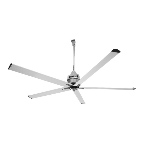
Summary of Contents for Vortice Nordik HVLS Super Blade Series
- Page 1 Instruction booklet Nordik HVLS Super Blade COD. 5.571.084.407 20/11/2019...
-
Page 2: Table Of Contents
CONTENTS INTRODUCTION ............3 1.1 General warnings . -
Page 3: Introduction
1 INTRODUCTION... -
Page 4: Glossary And Pictograms
The Manufacturer is able to provide further copies of the Instruction Manual and the enclosed Assembly Manual for the machine, if requested by the User. Such requests should be sent to Vortice Technical Dept. (www.vortice-italy.com) Recipients This Manual and the enclosed Assembly Manual are addressed to: The Installer, Operator, and Qualified Per-son- nel authorised to carry out maintenance tasks in the machine. - Page 5 GLOSSARY (Ann. I p. 1.1.1 Dir. 2006/42/EC) A potential source of injury or harm to one's health. DANGER Any zone inside and/or in proximity to the machine in which the presence of a person constitutes a risk to the health and safety of that person. DANGER ZONE Any person that finds themselves fully or partially in a danger zone EXPOSED PERSON...
- Page 6 PICTOGRAMS RELATED TO THE OPERATOR QUALIFICATIONS Symbol Description General operator: an operator without specific skills, only able to carry out simple tasks according to the instructions of qualified technicians. Lifting and handling gear operator: an operator authorised to use lifting gear and for handling materials and machines (strictly according to the manufacturer's instruc- tions), according to the laws in force in the country in which the machine is used.
- Page 7 PICTOGRAMS RELATED TO THE MACHINE STATUS The pictograms enclosed in a square / rectangle, provide INFORMATION. Symbol Machine status Machine off: with the electrical and pneumatic power supplies disconnected. Machine running: operating in automatic mode, with mobile guards closed, related interlocking devices activated, and fixed guards closed.
- Page 8 SAFETY PICTOGRAMS Pictograms contained with a triangle indicate DANGER. Pictograms contained within a circle impose a PROHIBITION/OBLIGATION Pictogram Name High voltage danger Entanglement Dragging General danger Do not remove the safety devices Cleaning, oiling, greasing, repairing, or adjusting moving parts manually forbidden. Obligation to disconnect the power supply before starting work or repairs.
-
Page 11: Diclarations
This machine was made in conformity with the pertinent European Directives applicable at the time it was put on the market EC Declaration of Conformity VORTICE ELETTROSOCIALI S.p.A declare that products in the NORDIK HVLS SUPER BLADE RANGE range conform with European Directives... -
Page 12: Description Of The Parts
Description of the parts Parts that make up the ceiling fan NUM. DESCRIZIONE Q.TA Motor rod holder Welded rod holder Tempered shaft hub Fissing plate Rod 50X50 drilled and galvanized Washer 10.5X20 H2 galvanized UNI 6592 Self-locking nut M10 galvanized UNI 7474 Screw M10X45 TH galvanized UNI 4018 Screw 10X35 TH galvanized UNI 4018 Safety holder... - Page 13 Bottom cap Fig. 3...
-
Page 14: Transportation And Handling
3 TRANSPORTATION AND HANDLING Vortice S.p.A. goal is to attain maximum respect for the environment. To this end, and to facilitate the greatest effi- ciency possible for the end client, it avoids the use of unnecessary or excessive packaging as much as possible, in order to minimise the environmental impact. -
Page 15: Warranty
Vortice S.p.A.'s part, and must be seen to be the user's risk and danger due to un- foreseeable use. -
Page 16: Installation
Then check that all the connections necessary for the equipment to work have been formed correctly by expert per- sonnel, according to all the specific disciplines in this regard. Vortice S.p.A. does not accept any responsibility for damage and/or malfunctioning due to connecting the product to the power supply in a manner that does not con- form to the requirements laid down herein. -
Page 17: Tightening Torque
Tightening torque It is necessary use a torque wrench or a calibrated screwdriver in order to respect the following tightening torque: • M8 Screw: 27 Nm • M10 Screw: 53 Nm • M12 Screw: 92 Nm Tie bars The Manufacturer markets and provides a specific metal tie bar kit for the ceiling fan, supplied if requested by the purchaser. -
Page 18: Operation
The installation must include a device for disconnecting the equipment from the mains power supply. A protec-tive fuse must also be installed, adequately sized and of a delayed type for starting motors. Attaching or hanging any object from the ceiling fan's blades for any reason, is forbidden. This is because such actions could result in the machine being out of balance, with a resulting anomalous distribution of loads and consequences such as the ma- chine falling. -
Page 19: Maintenance
7 MAINTENANCE Before doing any maintenance work, isolate the equipment from the power supply! Routine maintenance The product must be kept clean and protected against agents that may harm its integrity or use. The machine does not require routine maintenance. Periodic checking Frequency Activity... -
Page 20: Extraordinary Maintenance
Extraordinary maintenance Extraordinary maintenance refers to work on the electronic board, and replacing blades or other mechanical parts. The methods are described in the assembly manual enclosed. ALL maintenance operations, including extraordinary maintenance tasks, must be strictly done with the ma-chine stopped and disconnected from the electricity supply, by a specialist operator trained as indicated in this manual. -
Page 21: Spare Parts List
Vortice S.p.A., as well as any works done by operators not authorised for the purpose by the Manufacturer, or trained by them Orders are to made, indicating the following information: •... -
Page 22: Troubleshooting
9 TROUBLESHOOTING Before doing any maintenance work, isolate the equipment from the power supply and shut off the water supply! Vortice Elettrosociali S.p.A. Strada Cerca, 2 Frazione di Zoate 20067 Tribiano (Milano) ITALY www.vortice-italy.com Ph: (+39) 02 906991... - Page 23 Attachment 1 Assembly Instructions Before proceeding with the next steps, make sure you have completely read and understood the Instructions Manual.
- Page 24 Handling This Destratification Fan is relatively heavy and cumbersome, so it must be lifted and handled only after ensuring that the following have been made available: necessary and suitable equipment, all the safety conditions necessary for the required operations, and personnel that is educated and trained for use of the equipment and the specific work to be performed, equipped with the personal protective equipment required by the work itself and by applicable local regulations.
- Page 25 INVERTER MOTOR QUICK CONNECTORS ELECTRONICS...
- Page 26 MACHINE type Protection rating IP of the motor: IP 65 Inverter developed according to EMC regulations against interference with the power supply network The electrical connections use quick connectors for wiring that make it possible to speed up installations and any replacements.
- Page 27 Identification data Each machine is identified by a motor plate on which its reference data is indelibly marked. Always quote these references for any communication with the manufacturer or support centres.
- Page 28 Destratification Fan assembly...
- Page 29 Assembling the hub on the tapered shaft TAPERED SHAFT HUB INVERTER MOTOR Insert the hub on the shaft in the direction indicated in the figures. The narrower cylindrical part must be touching the motor. DO NOT FASTEN THE HUB IN THIS STEP...
- Page 30 Fall protection plate assembly Position the fall protection plate shims on the corresponding fixing holes of the motor, aligning one shim hole with the 7-pin connector and the second with the next hole on the right of the connector (as shown in the images). 2 FALL PROTECTION SHIMS 2 FALL PROTECTION PLATES 4 GROWN WASHER DIAM.
- Page 31 Fall protection plate assembly Position the two fall protection plates on the motor as shown in the figure, matching the holes highlighted in red. Then, fasten the plate to the motor with the 4 screws, preceded by the relative wa- shers.
- Page 32 Assembling the Starwheel on the Destratification Fan CAUTION: With the motor with the hub upwards (as on the previous page), position the Starwheel with the side shown in the photo upwards in the appropriate housing. Be especially careful with the angles of inclination of the Starwheel.
- Page 33 Blade fixing starwheel assembly: blade fixing disc Position the blade fixing disc so as to centre the innermost holes of the starwheel and the holes on the drive shaft. Then fix the disc to the starwheel with the appropriate screws (shown on the left), so that the screw head faces upwards as in the figure.
- Page 34 Blade fixing starwheel assembly: Shaft fixing Fixing the blade fixing disc to the shaft using the corresponding screws shown in the figure 2 GROWER WASH. D.8 GALV 2 SCREWS M8X20 STAIN.STEELA4...
- Page 35 Motor support bracket assembly 4 SCREW M10X35 TE GALV 8 WASH. 10.5X20 H2 GALV 4 SELF-LOCK. NUT M10 GALV MOTOR SUPPORT BRACKET To assemble the bracket, you need to rotate the motor, resting it on the starwheel. Position the bracket over the motor so as to centre the holes on the fall protection plate.
- Page 36 Assembling the Blade on the Blade POSITION THE BLADE TERMINAL IN THE BLADE HOUSING FIX WITH SCREW - WASHERS AND NUT. BLADE TERMINAL SCREW M8x40 TCEI GALV WASHER 8.4x16 H1.6 GALV SELF-LOCK. NUT M8 GALV MACHINED BLADE...
- Page 37 Assembling the Blade on the Destratification Fan Blade assembly is to be carried out with the destratification fan positioned on the ceiling 15 SCREW M8x60 TCEI GALV 30 WASHER 8x24 H2 GALV 15 SELF-LOCK. M8 CAUTION: The screws must be fixed with the relative screw head on the lower part of the blade POSITION THE BLADE IN THE STARWHEEL...
- Page 38 Assembling the 5-part bent reinforcement Starwheel - Instructions Follow the correct sequence as indicated for correct assembly: 5 SCREW M8x60 TCEI GALV 10 WASHER 8x24 H2 GALV 5 SELF-LOCK. M8 5-PART BENT REINFORCE- MENT STARWHEEL Fix without tightening the 5 central screws of the reinforcement starwheel to the main one with washers and nuts.
- Page 39 Assembling the 5-part bent reinforcement Starwheel - Instructions • Insert the remaining 2 screws with nut and washers in each blade, without tightening them; • Cross-tighten the 5 central screws, already aimed previou- sly; • Cross-tighten the blade fixing screws. Complete Destratification Fan Assembly CLOCKWISE direction of rotation (seen from below)
- Page 40 Support bracket and rod assembly ROD GALV 5 SCREW M12X90 TETF GALV 10 WASHER M12X36 H2.5 GALV 5 SELF-LOCK. NUT M12 GALV ROD SUPPORT BRACKET Insert the rod in the motor support bracket on the side where the three holes are present. The opposite side of the rod, with the two holes, must be inserted in the rod support bracket, as shown in the figures on the right.
- Page 41 Connector assembly Insert the power and signal connectors into the management board, making sure that the tooth on the male (1) matches up with the groove on the female (2). The power and signal connectors must be connected to the respective males on the circuit board.
- Page 42 Destratification fan disassembly: power supply Cut off the power and remove the power and signal connectors...
- Page 43 Destratification Fan Disassembly - BLADES - Operation with Inverter motor fixed to the ceiling CAUTION: This operation requires the use of a support or equipment suitable to sup- port the weight of the blades. Prepare the support BEFORE UNSCREWING 15 SCREW M8x60 TCEI GALV 30 WASHER 8x24 H2 GALV 15 SELF-LOCK.
- Page 44 Destratification Fan Disassembly - WINGLET - Operation with Blade on the Ground Unscrew the screw holding the plastic Winglet to the blade BLADE TERMINAL SCREW M8x40 TCEI GALV WASHER 8.4x16 H1.6 GALV SELF-LOCK. NUT M8 GALV MACHINED BLADE...
- Page 45 Destratification Fan Disassembly - INVERTER MOTOR - Operation with Inverter motor fixed to the ceiling UNSCREW THE SCREWS FIXING THE ROD ON THE BRACKET Unscrew the screws fixing the rod on the bracket 5 SCREW M12X90 TETF GALV 10 WASHER M12X36 H2.5 GALV 5 SELF-LOCK.
- Page 46 Destratification fan disassembly: motor support bracket 4 SCREW M10X35 TE GALV MOTOR SUPPORT BRACKET 8 WASH. 10.5X20 H2 GALV 4 SELF-LOCK. NUT M10 GALV After having set the inverter motor on the ground, remove the bracket fixing screws.
- Page 47 Destratification fan disassembly: blade fixing disc Before starting, overturn inverter motor so that the blade fixing starwheel is on the upper side 2 GROWER WASH. D.8 GALV 8 WASH. 10.5X20 H2 GALV BLADE FIXING DISC 2 SCREWS M8X20 STAIN.STEELA4 4 SCREW M10X45 TE GALV 4 SELF-LOCK.
- Page 48 Destratification Fan Disassembly - BLADE FIXING DISC - Operation with Inverter Motor on the Ground Unscrew the screws fixing the disc to the shaft and to the tapered shaft hub and slide off the star- wheel CAUTION: Overturn the motor 180° to perform this operation 8 WASH.
- Page 49 Destratification fan disassembly: fall protection plates Fall protection shim Fall protection plate 4 Grown washer diam. 8 GALV 4 Screws M8x25 TE GALV Remove the screws fixing the fall protection plate to the motor...
- Page 50 DESTRATIFICATION FAN DISASSEMBLY - SHAFT HUB - Operation with Inverter Motor on the Ground Slide off the fall protection plates and remove the hub from the shaft CAUTION: The tapered shaft hub will stay locked on the shaft - Use a bearing extractor to disassemble it...
- Page 51 Circuit board assembly Position the black insulation gasket Position the motor part so that the motor cables are toward the left. between the motor and the drive with the gasket holes matching up with those of the relative M5 screws...
- Page 52 Circuit board assembly Insert the faston connectors on the motor phase electronics according to the follo- wing diagram: U - Black V - Grey W - Brown PE - Yellow/Green (ground)
- Page 53 Circuit board assembly Insert the motor temperature sensor green connector, with White/Red wires, in the corresponding connector on the electronics (positioned as shown in the figure).
- Page 54 Circuit board assembly When closing, run the cables behind the electrolytic capacitors (shown in the figure on the left). CAUTION! The signal and power connectors must be on the front with the motor cable output on the left (as previously positioned). Electrolytic capacitors Close with the 6 M5 screws...
- Page 55 Electric connection...
- Page 56 Power connection The power supply must be provided by means of a line made with cable accor- ding to present load; Energy power distribution is composed according to wire diagram supplied. Power panel protect in MT (magnetotermic protection) line powering HVLS fan in one single area.
- Page 57 Shilded wire must be provided only from power panel side and not from fan side. In case on signal line you are going to install junction boxes to connect single fan signal line to main line, between junction boxes and signal connector from inverter you must use same wire RS485 used for signal line.
- Page 58 Modbus Address label Motoinverter type and Serial Num- Inverter parameterization Blades ber label Diameter Set label...
- Page 59 Fan line connection scheme THREE-POLAR BABLE...
- Page 60 Existing system wiring diagram SUPPLY LINE 200-480V THREE-PHASE 50/60 Hz MAIN SWITCH Differential type A Linea dedicata protetta opportunemente con Interruttore magneto-termico e Differenziale di Classe A con sensibilità di almeno 300 mA. La linea deve essere presa a valle dell'interruttore generale USER LINE 1 USER LINE 2 dell'impianto ed essere indipendente dalla altre linee che...
- Page 61 Multi-wire diagram for system wiring (single-phase) MAIN SWITCH SUPPLY LYNE 220V SINGLE-PHASE 50/60 Hz MT and Differential type A POWER BOX 220V SINGLE-PHASE 50/60 Hz THREE - POLAR CABLE + PE...
- Page 62 Multi-wire diagram for system wiring (three-phase) MAIN SWITCH SUPPLY LINE 200-480V THREE-PHASE 50/60 Hz MT and Differential type A POWER BOX THREE-POLAR CABLE + PE...
- Page 63 Connector Diagram and Pin Color for Single-Phase Connection CONNETTORE ALIMENTAZIONE MONOFASE CONNETTORE SEGNALE MONO - POLAR SUPPLY CONNECTOR IN/OUT CONNECTOR MARRONE BIANCO / ARANCIONE ARANCIONE GRIGIO BIANCO / BLU GIALLO / VERDE 1 : MODBUS A 2 : L2 2 : MODBUS B 3 : L1 3 : MODALITÀ...
- Page 64 Connector Diagram and Pin Color for Three-Phase Connection CONNETTORE ALIMENTAZIONE TRIFASE CONNETTORE SEGNALE THREE-PHASE SUPPLY CONNECTOR IN/OUT CONNECTOR MARRONE BIANCO / ARANCIONE NERO ARANCIONE GRIGIO BIANCO / BLU GIALLO / VERDE 1 : MODBUS A 1 : L3 2 : MODBUS B 2 : L2 3 : MODALITÀ...
- Page 65 SCATOLA COMANDI POTENZIOMETRO NB: It is necessary pull the A VOR-12832 and B wires down to the con- trol box for the Modbus con- nection, used for maintenance and diagnostic actions. Electric Scheme - Option 1: External Potentiometer Vortice code: 12832...
- Page 66 NB: It is necessary pull the A and B wires down to the con- trol box for the Modbus con- nection, used for maintenance and diagnostic actions. Electric Scheme - Option 2: External Potentiometer with DIN box Vortice code: 12828...
- Page 67 (0-10 V) 4-20 mA NB: It is necessary pull the A and B wires down to the control box for the Modbus connection, used for maintenance and diagnostic actions. Electric Scheme - Option 3: VORT T Control Box Vortice Code: 21137...
- Page 68 First Start-up Once machine assembly, installation and electrical connection has been completed, power up the machine and wait about 30 seconds for it to stop its self-diagnosis of default parameters and to start rotating. Then check that: - there are no installation imbalances due to incorrect assembly of the components or latent their defects.
- Page 69 IMPORTANT INFORMATION ON ENVIRONMENTALLY COMPATIBLE DISPOSAL IN CERTAIN EUROPEAN UNION COUNTRIES THIS APPLIANCE IS NOT SUBjECT TO THE REQUIREMENTS OF NATIONAL LAWS IMPLEMENTING THE WEEE DIRECTIVE; CONSEQUENTLY, THERE IS NO OBLIGATION TO OBSERVE SORTED COLLECTION PROCEDURES WHEN DISPOSING OF THE APPLIANCE IN THESE COUNTRIES.
- Page 72 La società Vortice S.p.A. si riserva il diritto di apportare tutte le varianti migliorative ai prodotti in corso di vendita. The company Vortice S.p.A. reserves the right to make improvements to products at any time and without prior notice. La société Vortice S.p.A. se réserve le droit d'apporter toutes les variations afin d'améliorer ses produits en cours de commercialisation.
Need help?
Do you have a question about the Nordik HVLS Super Blade Series and is the answer not in the manual?
Questions and answers