Table of Contents
Advertisement
Quick Links
USER GUIDE FOR WIRELESS
ULTRASONIC LEVEL SENSOR
WS433-ULC
WS433-ULC-MN-EN-01
This document is applied for the following products
SKU
WS433-ULC
Item Code
WS433-ULC-01
1. Functions Change Log
HW Ver.
2.5
2. Introduction
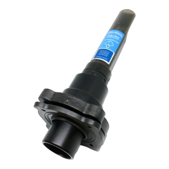
Wireless Ultrasonic Level Sensor is a combination of wireless sensor transmitter WS433-M12F and Ultrasonic level
sensor, measure the level of liquid surface of water, oil ... This level sensor utilises the ultrasonic technology to
measure the surface of liquid or solid, the principle is to measure the time of flight of the ultrasound pulse in the air
environment. The wireless portion is Sub-GHz technology from Texas Instruments allows long range transmission at
ultra-low power consumption. It will connect 2-way wirelessly to the wireless co-ordinator WS433-CL to send data and
receiving the configuration. It can be configured the operation parameters like data sending interval, health check
cycle...remotely from Globiots platform or via ModbusRTU software (thru the WS433-CL). Its default data rate is 50
kbps, can be switched to 625 bps to increase the communication range. It can last up to 10 years with a single AA
battery. There are many applications such as monitoring of river water levels, water tanks, etc.
HW Ver.
2.5
Wireless Ultrasonic Level Sensor Sensor 433MHz, 6000mm range, type AA 1.5VDC battery, IP67
FW Ver.
5.0
FW Ver.
Release Date
DEC-2019
MAR-2021
5.0
Functions Change
Change RF data rate by
button
Advertisement
Table of Contents

Related Manuals for daviteq WS433-ULC


Summary of Contents for daviteq WS433-ULC
- Page 1 USER GUIDE FOR WIRELESS ULTRASONIC LEVEL SENSOR WS433-ULC WS433-ULC-MN-EN-01 MAR-2021 This document is applied for the following products WS433-ULC HW Ver. FW Ver. Item Code WS433-ULC-01 Wireless Ultrasonic Level Sensor Sensor 433MHz, 6000mm range, type AA 1.5VDC battery, IP67 1. Functions Change Log HW Ver.
-
Page 2: Specification
01 x AA 1.5-3.6VDC, up to 10-year operation, depends on configuration Frequency Band ISM 433Mhz, Sub-GHz technology from Texas Instrument, USA ETSI EN 300 220, EN 303 204 (Europe) FCC CFR47 Part15 (US), ARIB International Compliance STD-T108 (Japan) Vietnam Type Approval Certification QCVN 73:2013/BTTTT, QCVN 96:2015/BTTTT (DAVITEQ B00122019) -
Page 3: Typical Applications
Security Standard AES-128 Operating temperature of PCB -15°C..+60°C (with AA L91 Energizer) Housing Poly-carbonate, IP67 Product dimensions & weight 160x30x30mm, < 250g (without battery) Box dimension & gross weight 190x50x50mm, < 300g 4. Typical Applications 5. Operation Principle 5.1 The Effective Detection Range... - Page 4 The Effective Detection Range 5.2 Process of measurement 5.2.1 Measurement principle of Wireless Sensor When the sensor sampling time interval is reached, For example minutes, the node will wake up and switch ON the power supply to supply the energy to external sensor to start the measurement. Depends on the type and characteristic of external sensor, the sensor will take a certain time to finish the measurement.
- Page 5 X: the raw value from the sensor Y: the calculated value will be sent to LoRaWAN Gateway in the payload data. a: constant (default value is 1) b: constant (default value is 0) So, if there is no user setting for a and b ==> Y = X The Y value will be compared with Lo and Hi threshold.
- Page 6 From here we can look up the water level corresponding to the measured distance of the sensor by the formula: Y = aX + b. Where: X is the measured distance (mm) and Y is the level (‰) Distance (mm) Level (‰) 1000 1000...
- Page 7 (add up to 40 nodes) . After 5 minutes Enb_auto_add_sensors will automatically = 0. Memmap resgisters You can download Modbus Memmap of WS433-CL with the following link: https://filerun.daviteq.com/wl/?id=WBbGm89AToHWyvIyMOc780N1KmjfUr3Y 5.2.2 Add sensor node into WS433-CL-04 (1) through intermediate WS433-CL-04 (2) and Modbus In case the sensor need to be added to WS433-CL-04 (1) has been installed in a high position, the sensor cannot be brought close to WS433-CL-04 (1).
-
Page 8: Button Function
5.4 Button Function Open the cover of sensor then use the push button to set the data transfer speed for the first 30 seconds when the battery is first installed, after 30 seconds the push button function does not work. Press and hold the button for 2 seconds =>... - Page 9 Num of Node will indicate the number of nodes managed by WS433-CL. Every time a node is added, the Num of Node will increase by 1. Every time a node is deleted, the Num of Node is reduced by 1. Writing Num of Node = 0 will delete all 40 node ids to 0.
- Page 10 Step 2: Open Modbus tool on PC You can download Daviteq Modbus Configuration Tool with the following link: https://filerun.daviteq.com/wl/?id=qK0PGNbY1g1fuxTqbFW9SXtEvCw7bpc6 Template File: https://filerun.daviteq.com/wl/?id=hgrjOg3wwvyrvAZ54p8iZiFpDyXTcnec How to use the Modbus configuration software Unzip file and run file application "Daviteq Modbus Configuration Tool Version"...
- Page 11 Step 3: Configure parameters of the sensor. Memmap resgisters You can download Modbus Memmap of WS433-CL with the following link: https://filerun.daviteq.com/wl/?id=BKEaUzdArkoc0Hc7nfpRShdPVToVrqQZ In the memmap file, refer to the Memmap of WS433-ULB & ULC sheet to configure the sensor's operating parameters accordingly.
- Page 12 Value from ultrasonic Level value level of sensor sensor. This Node float Read value is (parameter parameter 1 of a wireless sensor node Value from ultrasonic Distance level value of sensor. This sensor float Read value is Node parameter (parameter 2 of a wireless sensor node...
-
Page 13: Installation Location
NOTE: Integrated WS433-CL / iConnector Coordinator The coordinator must be placed at least 4 meters above the ground and the WS433-ULC clearly visible. 6.2 Process mounting WARNINGS: 1. Please make sure the fluid is suitable with the wetted materials of the sensor. Please refer sensor specification;... -
Page 14: Battery Installation
6.3 Battery installation Steps for battery installation: Step 1: Using Philips screw driver to unscrew M2 screw at the side of housing. Step 2: Pull out the cover then insert the AA 1.5VDC battery, please take note the poles of the battery. ATTENTION:... -
Page 15: Troubleshooting
Because of O-ring, it requires to have much pulling force at the beginning, therefore please do it carefully to avoid the damage of circuit board which is very thin (1.00mm); REVERSED POLARITY OF BATTERIES IN 10 SECONDS CAN DAMAGE THE SENSOR CIRCUIT ! Step 3: Insert the top plastic housing and locking by M2 screw 7. - Page 16 No.11 Street 2G, Nam Hung Vuong Res., An Lac Ward, Binh Tan Dist., Ho Chi Minh City, Vietnam. Templogger Pty Ltd Tel: +84-28-6268.2523/4 (ext.122) Tel: 1800 LOGGER Email: info@daviteq.com | www.daviteq.com Email: contact@templogger.net Revision #10 Created Fri, Mar 26, 2021 1:37 AM by Kiệt Anh Nguyễn Updated Mon, Aug 30, 2021 10:24 AM by Kiệt Anh Nguyễn...
Need help?
Do you have a question about the WS433-ULC and is the answer not in the manual?
Questions and answers