Table of Contents
Advertisement
Quick Links
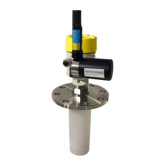
USER GUIDE FOR WIRELESS
RADAR LEVEL METER
WS433-MA-RD-MN-EN-01
This document is applied for the following products
SKU
WS433-MA
Item Code
WS433-MA-31
SKU
RD269X
RD2695S-P-B(J)-04-
Item Code
A3(04)-V-4-L-N-V-6
0. Configuration Check List
0.1 Wireless sensor configuration check list
STEP 1: Insert battery into the sensor
HW Ver.
2.5
Wireless Sensor 1-channel 0-20mA DC current input, IP67, battery AA 1.5VDC, 24VDC Output for
Instrument power supply
HW Ver.
26GHz RadarLevel transmitter, 78mm PVDF protection tube, SUS304 JIS10K 80A RF Flange, 0-6m
cablibrated range, 4-20mA output, looped power, HART, IP67 aluminum housing
FW Ver.
5.0
FW Ver.
NOV-2020
Advertisement
Table of Contents

Related Manuals for daviteq WS433-MA-31


Summary of Contents for daviteq WS433-MA-31
- Page 1 This document is applied for the following products WS433-MA HW Ver. FW Ver. Item Code Wireless Sensor 1-channel 0-20mA DC current input, IP67, battery AA 1.5VDC, 24VDC Output for WS433-MA-31 Instrument power supply RD269X HW Ver. FW Ver. RD2695S-P-B(J)-04- 26GHz RadarLevel transmitter, 78mm PVDF protection tube, SUS304 JIS10K 80A RF Flange, 0-6m...
- Page 2 1. Remove the battery cover of the sensor; 2. Insert a type D battery into the sensor. Please note the battery terminals for correct installation STEP 2: Add sensor to co-ordinator After inserting the battery for the sensor, power on the co-ordinator and bring the co-ordinator closer to the sensor to add the sensor automatically. STEP 3: Configure the sensor's operating parameters Use Modbus tool to check added sensors and configure sensor operating parameters.
- Page 3 STEP 1: Remove the battery 1. Remove the battery cover of the sensor; 2. Remove a type D battery in the sensor. STEP 2: Remove 4-20mA wires 1. Open the radar sensor cover; 2. Remove the 4-20mA wire plugged in the sensor. STEP 3: Power supply 24VDC to 2 pins 4-20mA on the Radar Sensor Power supply 24VDC to 2 pins 4-20mA on the Radar Sensor with 250 Ohm resistor connected in series.
-
Page 4: Specification
1. Functions Change Log HW Ver. FW Ver. Release Date Functions Change Change RF data rate by DEC-2019 button 2. Introduction This is a wireless sensor that measures water level using radar technology. The combination of a high-tech radar level sensor combined with a wireless sensor using Texas Instrument's advanced Sub-GHz technology enables long-range transmission with extremely low energy consumption. -
Page 5: Operation Principle
Antenna Internal Antenna, 3 dbi Battery 01 x AA 1.5VDC, up to 10-year operation, depends on configuration Frequency Band ISM 433Mhz, Sub-GHz technology from Texas Instrument, USA Receiving Sensitivity -110dBm at 50kbps ETSI EN 300 220, EN 303 204 (Europe) FCC CFR47 Part15 (US), ARIB International Compliance STD-T108 (Japan) Security Standard... - Page 6 the power supply to supply the energy to external sensor to start the measurement. Depends on the type and characteristic of external sensor, the sensor will take a certain time to finish the measurement. For example: the measurement time is 200mS, after this time, the node will read the value of sensor using I2C, node will switch OFF power supply to external sensor to save energy.
- Page 7 (add up to 40 nodes) . After 5 minutes Enb_auto_add_sensors will automatically = 0. Memmap resgisters You can download Modbus Memmap of WS433-CL with the following link: https://filerun.daviteq.com/wl/?id=BKEaUzdArkoc0Hc7nfpRShdPVToVrqQZ 4.1.2 Add sensor node into WS433-CL-04 (1) through intermediate WS433-CL-04 (2) and Modbus In case the sensor need to be added to WS433-CL-04 (1) has been installed in a high position, the sensor cannot be brought close to WS433-CL-04 (1).
- Page 8 Press and hold the button for 5 seconds => LED blinks twice => Release the button to set Data rate RF 625bps Press and hold the button for 10 seconds => LED blinks 3 times => Release the button to reset RF parameters (frequency, RF output power, data rate), if held for more than 30 seconds then the button function does not work.
- Page 9 Step 2: Open Modbus tool on PC You can download Daviteq Modbus Configuration Tool with the following link: https://filerun.daviteq.com/wl/?id=bU88UgTMDNPIXjafxwxQeU89JtAoXEZR Template File: https://filerun.daviteq.com/wl/?id=hgrjOg3wwvyrvAZ54p8iZiFpDyXTcnec How to use the Modbus configuration software Unzip file and run file application "Daviteq Modbus Configuration Tool Version 1.1"...
- Page 10 Use Modbus tool to check added sensors and configure sensor operating parameters. Memmap resgisters You can download Modbus Memmap of WS433-CL-FW with the following link: https://filerun.daviteq.com/wl/?id=WBbGm89AToHWyvIyMOc780N1KmjfUr3Y In the memmap file, refer to the Memmap of WS433-AI sheet to configure the sensor's operating parameters accordingly.
- Page 11 Below are examples of some typical sensor parameters: Function Function # of Value Code Code Byte Size Description Default Format Property Explanation register Range (Read) (Write) Battery level, only 04 levels: 10%, 30%, %Battery 60% and of sensor 10,30,60,99 uint16 Read 99% (full).
- Page 12 Configure operating frequency of wireless sensor by 433.05- ordinator, Radio 434.79, 433 433.92 float Read/Write should be frequency configured from 433.05- 434.79 MHz, only advanced users 4.2 Radar Sensor RD-2695S The Radar Level Transmitter antenna emits narrower micro wave pulses which will be transmitted via the antenna. The micro wave will be reflected back after touching the surface of a medium, then antenna system will receive it and transmit it into the electrical circuit, which will be automatically turned into the level signals.
-
Page 13: Wireless Sensor Installation
PLEASE REFER TO THE MANUFACTURER'S INSTRUCTIONS CAREFULLY TO AVOID DAMAGING THE DEVICE: USER MANUAL OF RADAR LEVEL METER INSTRUCTIONS FOR CONFIGURING SENSORS WITH LCD MODULE 5. Wireless sensor installation 5.1 Installation location To maximize the distance of transmission, the ideal condition is Line-of-sight (LOS) between the Wireless sensor and Gateway. - Page 14 5.2 Power supply and battery installation 5.2.1 battery installation Recommends using type D batteries for wireless sensors. ATTENTION: REVERSED POLARITY OF BATTERIES IN 10 SECONDS CAN DAMAGE THE SENSOR CIRCUIT ! Step 1: Remove the battery cover of the sensor Step 2: Insert a type D battery into the sensor 5.2.2 Power Supply Insert the power cord into the sensor via Cable Gland...
-
Page 15: Troubleshooting
Power supply 24VDC and GND into electric domino ATTENTION: WHEN CONNECTING A WIRING PLEASE PAY ATTENTION TO THE NAMES MARKED ON THE LINE REVERSED POLARITY CAN DAMAGE THE SENSOR CIRCUIT ! 6. Troubleshooting Phenomena Reason Solutions... -
Page 16: Support Contacts
No.11 Street 2G, Nam Hung Vuong Res., An Lac Ward, Binh Tan Dist., Ho Chi Minh City, Vietnam. Tel: +84-28-6268.2523/4 (ext.122) Templogger Pty Ltd Email: info@daviteq.com | www.daviteq.com Tel: 1800 LOGGER Email: contact@templogger.net Revision #16 Created Tue, Nov 3, 2020 8:38 AM by Kiệt Anh Nguyễn...
Need help?
Do you have a question about the WS433-MA-31 and is the answer not in the manual?
Questions and answers